

Page 1
R
The following instructions are a guide for the proper installation of Victaulic Style 441 Stainless Steel Vic-Flange Adapters. Proper installation requires pipe that is prepared and grooved
in accordance with the latest Victaulic specifications.
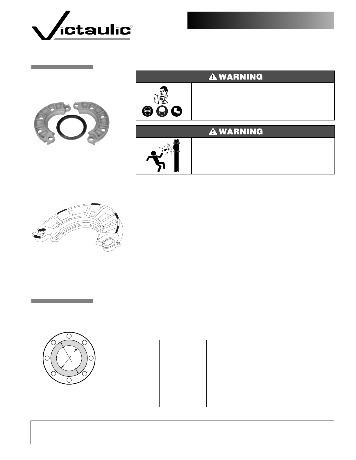
• The Style 441 is designed for use with Class 150 raised-face flanges, in accordance with
ANSI B16.5. When a Style 441 is used with a flat-faced flange, the raised projections on
the outside edge and around the mating holes of the flange adapter must be ground flush
to the body. The shaded areas on the sketch to the left identify the projections that need
to be ground flush on both segments.
• The Style 441 cannot be used, unless it mounts flush to the mating flange; therefore,
flange washers, or anything else that prevents flush mounting, cannot be used.
• The Style 441 must not be used as anchor points for tie rods across non-restrained joints.
• The Style 441 must not be used against rubber coated surfaces or with wafer or lug-type
valves, or when the flange adapter does not mount flush with the mating flange.
• Because of the outside flange dimension, the Style 441 must not be used 90° to one
another on a standard fitting.
1.
2.
Installation Instructions
Style 441
®
Adapter
IMPORTANT
INFORMATION
Stainless Steel Vic-Flange
2 - 6" (60,3 - 168,3 mm)
• Read and understand all installation instructions before attempting to install any
Victaulic piping products.
•Wear hardhat, safety glasses, and foot protection.
Failure to follow these instructions could result in serious personal injury, property
damage, and/or product damage.
• Depressurize and drain piping systems before attempting to install, remove, or
adjust any Victaulic piping products.
Failure to follow these instructions could result in serious personal injury and/or
property damage.
ALWAYS VERIFY THAT THE GASKET IS SUITABLE FOR THE INTENDED SERVICE. Refer to publication 05.01 for complete information.
PIPE AND MATING
FACE PREPARATION
A
B
Figure 1
VICTAULIC® IS AN ISO 9001 CERTIFIED COMPANY
Victaulic Company of America
Phone: 1-800-PICK-VIC (1-800-742-5842)
Fax: 610-250-8817
e-mail:pickvic@victaulic.com
I-441
3307 Rev.B 8/02 © Copyright 2002, Victaulic ® Registered Trademark of Victaulic Printed in U.S.A Z000441000
Victaulic Company of Canada
Phone: 416-675-5575
Fax: 416-675-5565
e-mail: viccanada@victaulic.com
PIPE SIZE
Nominal
Diameter
in/
2 2.375 2.40 3.40
50 60,3 61 86
2
65 73,0 74 99
3 3.500 3.50 4.50
80 88,9 89 114
4 4.500 4.50 5.50
100 114,3 114 140
6 6.625 6.60 7.80
150 168,3 168 198
mm
¹⁄₂
Actual
Out. Dia.
in/
mm
2.875 2.90 3.90
Sealing Surface
“A” Max. “B” Max.
Victaulic Europe
Phone: 32-9-381-1500
Fax: 32-9-380-4438
e-mail: viceuro@victaulic.be
inches/
mm
the pipe end to the groove) must be
smooth and free from indentations, projections, and roll marks to provide a
leak-tight seal for the gasket. All rust,
loose scale, oil, grease, and dirt must be
removed.
ure 1) must be free from gouges, undulations, or deformities of any type for
proper sealing.
Victaulic America Latina
Phone: 610-559-3300
Fax: 610-559-3608
e-mail: vical@victaulic.com
The outside surface of the pipe (from
The gray area of the mating face (Fig-
Victaulic Asia Pacific
Phone: 65-6235-3035
Fax: 65-6235-0535
e-mail: vicap@victaulic.com
Page 2
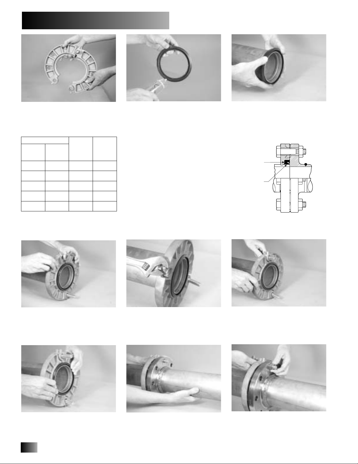
Figure 2
Gasket
Position
Gasket
Markings
3.
6.
9.
1.
4.
7.
✕
✕
✕
Installation Instructions
✕
✕
2.
5.
8.
Insert a standard bolt through a mating hole to act as a hinge, as shown
above.
BOLT REQUIREMENTS
PIPE SIZE
Nominal
Diameter
mm
in/
2 2.375
50 60,3
2
¹⁄₂
65 73,0
3 3.500
80 88,9
4 4.500
100 114,3
6 6.625
150 168,3
*Bolts are not supplied by Victaulic. When using stainless
steel bolts/nuts, consideration should be given to using
an anti-seize lubricant on the threads.
Actual
Out. Dia.
in/
2.875
mm
Number of
Bolts
Required*
4
4
4
8
8
Bolt Size
inches
⁵⁄₈
2
³⁄₄
⁵⁄₈
3
⁵⁄₈
3
⁵⁄₈
3
³⁄₄
3
¹⁄₂
Check the gasket supplied to make
sure it is suitable for the intended service. The color code identifies the gasket grade. Apply a thin coat of Victaulic
lubricant or silicone lubricant to the
gasket lips and exterior.
Install the gasket onto the pipe end.
Make sure the gasket is properly positioned, as shown in Figure 2 below.
NOTE: The markings on the outside of
the gasket must face the Style 441
flange adapter.
Place the hinged flange around the
grooved pipe end. Make sure the key
section of the flange adapter engages in
the pipe groove.
Make sure the gasket is still seated
properly in the flange adapter.
2
Closure lugs are provided to ease
installation. Clamp both lugs with a
wrench or pliers, and pull the two segments together until the bolt holes
align.
Join the mating flange with the VicFlange by aligning the two bolts with
the mating flange’s holes.
When the bolt holes are aligned,
insert a standard bolt through the other
mating hole.
Install a nut onto the two bolts.
Tighten until the nuts are finger-tight.
Page 3

Installation Instructions
10. Install the remaining standard bolts
through the Vic-Flange and the mating
flange. Install all nuts until they are
finger-tight.
11. Tighten all nuts evenly in a crossing
pattern, as with a regular flange assembly. Continue to tighten all nuts until
the standard, flange-joint torque recommendation is achieved.
This product shall be manufactured by Victaulic Company. All products to be installed in accordance with current Victaulic installation/assembly instructions.
Victaulic reserves the right to change product specifications, designs and standard equipment without notice and without incurring obligations.
3
 Loading...