

Page 1

OPERATING AND MAINTENANCE INSTRUCTIONS MANUAL
RG3210 Roll Grooving Tool
WARNING
Original Instructions
WARNING
Failure to follow instructions and warnings could result in death,
serious personal injury, property damage, and/or product damage.
• Before operating or servicing any grooving tools, read all
instructions in this manual and all warning labels on the tool.
• Wear safety glasses, hardhat, foot protection, and hearing
protection while working around this tool.
• Save this operating and maintenance manual in a place
accessible to all operators of the tool.
If you need additional copies of any literature, or if you have questions concerning the safe
and proper operation of this tool, contact Victaulic, No.13, Tieshan Dong 2 Road,
DaLian Development Zone, Dalian, China 116630, Phone: 86-411-39213600,
E-Mail: vicap@victaulic.com
REV_E
TM-RG3210
Page 2

Page 3

TABLE OF CONTENTS
Hazard Identification ................. 4
Operator Safety Instructions ............ 4
Introduction ....................... 6
Receiving the Tool ....................6
Container Contents ...................6
Power Requirements ................. 7
Extension Cord Requirements ...........7
Tool Nomenclature................... 8
Tool Dimensions .................... 9
Tool Specifications .................. 9
Tool Setu p ........................ 9
Pre-Operation Adjustments.............10
Grooving Rolls ......................10
Preparing Pipe for Grooving ............10
Pipe Length Requirements.............10
Long Pipe Lengths...................11
Groove Diameter Stop Adjustment . . . . . . . 12
Grooving Operation ..................14
Lower Roll Removal ..................16
Upper Roll Removal..................16
Upper Roll Installation................17
Lower Roll Installation ................17
Maintenance .......................18
Hydraulic System....................18
PS3210 Pipe Stand ..................18
Replacement Parts ..................18
Troubleshooting.....................19
Explanation of Critical Roll Groove
Dimensions ..................... 20
Roll Groove Specifications for Steel Pipe .. 22
Tool Ratings for Steel Pipe............ 22
EC Declaration of Conformity .......... 23
3
REV_E
TM-RG3210 / Operating and Maintenance Instructions Manual
Page 4
HAZARD IDENTIFICATION
Definitions for identifying the various hazard
levels are provided below.
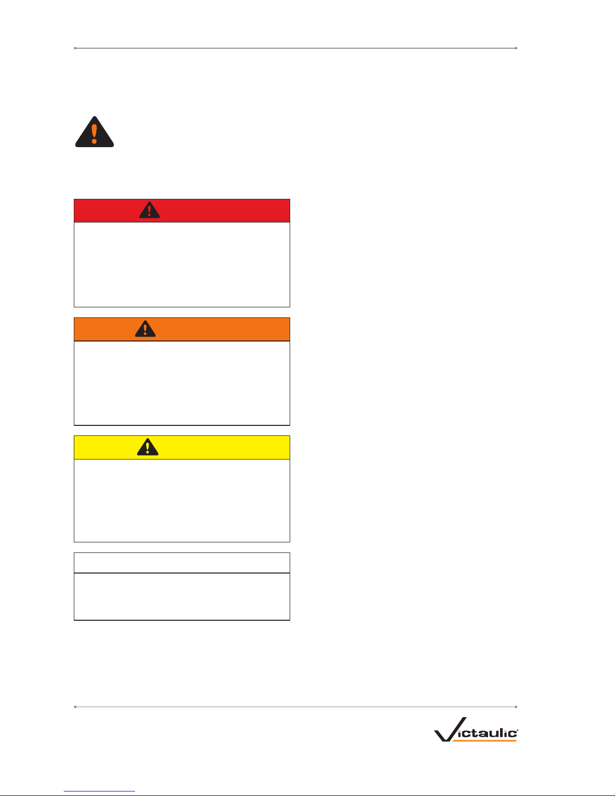
This safety alert symbol indicates
important safety messages. When
you see this symbol, be alert to the
possibility of personal injury.
Carefully read and fully understand the message
that follows.
DANGER
• The use of the word “DANGER” always
signifies an immediate hazard with
a likelihood of severe personal injury
or death if instructions, including
recommended precautions, are not
followed.
WARNING
• The use of the word “WARNING” signifies
the presence of hazards or unsafe
practices which could result in severe
personal injury if instructions, including
recommended precautions, are not
followed.
CAUTION
• The use of the word “CAUTION”
signifies possible hazards or unsafe
practices which could result in minor
injury and product or property damage
if instructions, including recommended
precautions, are not followed.
NOTICE
• The use of the word “NOTICE” signifies
special instructions which are important
but not related to hazards.
OPERATOR SAFETY
INSTRUCTIONS
The RG3210 is designed for the sole purpose
of roll grooving pipe. These instructions must
be read and understood by each operator
PRIOR to working with the grooving tools. These
instructions describe safe operation of the tool,
including setup and maintenance. Each operator
must become familiar with the tool’s operations,
applications, and limitations. Particular care
should be given to reading and understanding
the dangers, warnings, and cautions described
throughout these operating instructions.
Use of these tools requires dexterity and
mechanical skills, as well as sound safety
habits. Although these tools are designed and
manufactured for safe, dependable operation,
it is difficult to anticipate all combinations of
circumstances that could result in an accident.
The following instructions are recommended
for safe operation of these tools. The operator
is cautioned to always practice “safety first”
during each phase of use, including set up and
maintenance. It is the responsibility of the lessee
or user of these tools to ensure that all operators
read this manual and fully understand the
operation of these tools.
Store this manual in a clean, dry area where
it is always readily available. Additional copies
of this manual are available upon request
through Victaulic, or can be downloaded at
victaulic.com.
4
REV_E
TM-RG3210 / Operating and Maintenance Instructions Manual
Page 5
DANGER
1. Avoid using the tool in potentially
dangerous environments. Do not expose
the tool to rain, and do not use the tool in
damp or wet locations. Do not use the tool
on sloped or uneven surfaces. Keep the
work area well lit. Allow sufficient space to
operate the tool properly.
2. Ground the motor to protect the operator
from electric shock. Ensure that the motor
is connected to an internally grounded
electrical source.
3. Disconnect the power cord from the
electrical source before servicing the
tool. Only authorized personnel should
perform maintenance on the tool. Always
disconnect the power cord from the
electrical source before servicing or
adjusting the tool.
4. Prevent accidental startups. Place the
power switch in the “OFF” position before
connecting the tool to an electrical source.
WARNING
1. Prevent back injury. DO NOT attempt to
lift tool components without the use of
mechanical lifting equipment.
2. Wear proper apparel. Do not wear loose
clothing, jewelry, or anything that can
become entangled in moving parts.
3. Wear protective items when working with
tools. Always wear safety glasses, hard hat,
foot protection, and hearing protection.
4. Keep hands and tools away from grooving
rolls and stabilizer wheel during the
grooving operation. Grooving rolls can
crush or cut fingers and hands.
5. Do not reach inside pipe ends during tool
operation. Pipe edges can be sharp and
can snag gloves, hands, and shirt sleeves.
Never reach across moving parts.
6. Do not over-reach. Maintain proper footing
and balance at all times.
CAUTION
1. This tool is designed ONLY for
roll grooving pipe sizes, materials, and
wall thicknesses listed in the “Tool
Ratings for Steel Pipe” section.
2. Inspect the equipment. Before using the
tool, check all moveable parts for any
obstructions. Verify that tool components
are installed and adjusted in accordance
with the “Tool Setup” section.
3. Stay alert. Do not operate the tool if you are
drowsy from medication or fatigue.
4. Keep visitors, trainees, and observers
away from the immediate work area. All
visitors should be kept a safe distance from
the equipment at all times.
5. Keep work areas clean. Keep the
work area around the tool clear of any
obstructions that could limit movement of
the operator. Clean up any spills.
6. Secure the work, machine, and
accessories. Ensure that the tool is stable.
Refer to the “Tool Setup” section.
7. Support the work. Support long pipe/tubing
lengths with a pipe stand, in accordance
with the “Long Pipe Lengths” section.
8. Do not force the tool. Do not force the tool
or accessories to perform any functions
beyond the capabilities described in these
instructions. Do not overload the tool.
9. Maintain tool with care. Keep the tool
clean at all times to ensure proper and
safe performance. Follow the instructions
for lubricating tool components.
10. Use only Victaulic replacement parts
and accessories. Use of any other parts
may result in a voided warranty, improper
operation, and hazardous situations.
11. Do not remove any labels from the tool.
Replace any damaged or worn labels.
5
REV_E
TM-RG3210 / Operating and Maintenance Instructions Manual
Page 6

INTRODUCTION
NOTICE
• Drawings and/or pictures in this manual
may be exaggerated for clarity.
• The tool, along with this operating
and maintenance instructions manual,
contains trademarks, copyrights, and/or
patented features that are the exclusive
property of Victaulic.
The RG3210 is a hydraulic-feed shop or field
tool designed to roll groove carbon steel pipe
of various diameters and wall thicknesses. The
RG3210 is a completely self-contained unit with
a motor, power cord/plug, and hydraulic pump
handle.
CAUTION
• The RG3210 should only be used for roll
grooving pipe designated in the “Tool
Ratings for Steel Pipe” section of this
manual.
Use of the tools for other purposes, or use
exceeding the pipe thickness maximums,
will overload the tools, shortening tool life
and potentially causing tool damage.
RECEIVING THE TOOL
RG3210 tools are packed individually in sturdy
containers that are designed for repeated
shipping. Save the container for return shipment
of rental tools.
Upon receipt of the tool, ensure that all
necessary parts are included. If any parts
are missing, contact Victaulic.
CONTAINER CONTENTS
Qty. Description
1
Tool with Motor and Hydraulic Pump Handle
1
Foot Switch
1
PS3210 Pipe Stand
1
Roll Set Assembly (5 Rollers)
2
Operating and Maintenance Instructions Manual
The RG3210 is supplied with grooving roll sets
for carbon steel pipe. Rolls are marked with the
pipe size and part number.
6
REV_E
TM-RG3210 / Operating and Maintenance Instructions Manual
Page 7
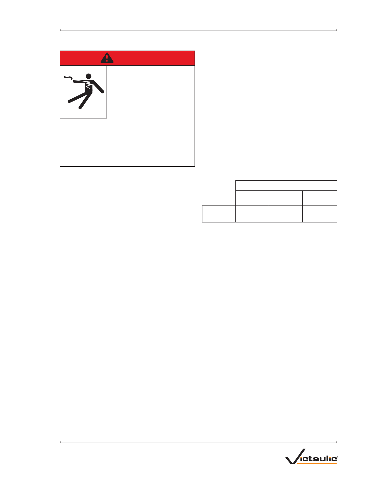
POWER REQUIREMENTS
DANGER
• To reduce the risk of
electric shock, check
the electrical source for
proper grounding and
follow all instructions.
• Before performing any repair or
maintenance, disconnect the tool from
the electrical source.
Failure to do so could result in death or
serious personal injury.
Maximum current draw is 8.5 amps.
The RG3210 tool must be grounded properly in
accordance with all local and national electrical
code requirements.
If an extension cord is required, refer to the
“Extension Cord Requirements” section.
EXTENSION CORD REQUIREMENTS
When pre-wired outlets are not available and
an extension cord must be used, it is important
to use the proper cord size (gauge). Cord size
selection is based upon tool rating and cord
length. Use of a cord size (gauge) thinner than
required will cause significant voltage drop at
the motor while the tool is operating. Voltage
drops may cause damage to the motor and can
result in improper tool operation. NOTE: It is
acceptable to use a cord size that is thicker than
required.
Listed in the chart below are recommended
cord size (gauge) for cord lengths up to and
including 31 meters. Use of extension cords
beyond 31 meters in length should be avoided.
Cord Lengths
8 meters 15 meters 31 meters
Cord Size
(Gauge)
12 gauge 12 gauge 10 gauge
7
REV_E
TM-RG3210 / Operating and Maintenance Instructions Manual
Page 8
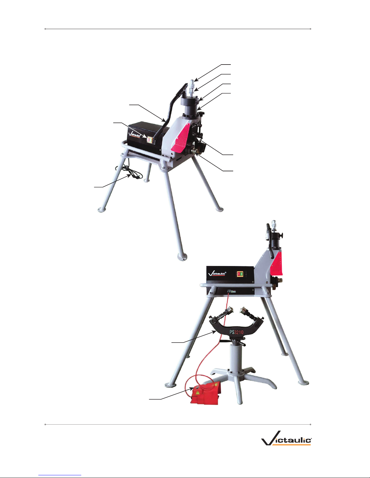
TOOL NOMENCLATURE
PS3210 Pipe Stand
Hydraulic Pump Handle
Lower Roll
Power Cord
Power Switch
Hydraulic Cylinder
Depth Adjuster Nut
Locking Nut
Hydraulic Pump Valve
Upper Roll
Foot Switch
8
REV_E
TM-RG3210 / Operating and Maintenance Instructions Manual
Page 9

TOOL SPECIFICATIONS
Tool weight: 137 kilograms
Voltage: 220-volt, single phase
Frequency: 50 Hz/60 Hz
Maximum working pressure: 8000 kg
Maximum oil cylinder pressure: 40 Mpa
Capacity of oil tank: 150 ml
TOOL SETUP
WARNING
• Do not connect power until instructed
otherwise.
• Tool must be lifted with a hoist and plate
clamp to safely handle the tool weight
(137 kilograms).
Failure to follow these instructions may
result in serious personal injury.
1. Remove all components and check to ensure
that all necessary items are included. Refer to
the “Receiving the Tool” section.
2. Select a location for the tool and pipe stand.
Choose a location that has:
a. The required power. Refer to the “Power
Requirements” section
b. The space necessary to adequately
handle the pipe to be grooved
c. A level surface for the tool and pipe
stand
3. Place the tool on a level surface. Place a
level on top of the motor to verify that the
tool is level front to back and side to side.
4. Make sure the hydraulic system is full of
oil. Refer to the “Maintenance” section for
hydraulic oil requirements.
TOOL DIMENSIONS
820 mm
1100 mm
1300 mm
9
REV_E
TM-RG3210 / Operating and Maintenance Instructions Manual
Page 10

PRE-OPERATION ADJUSTMENTS
Every RG3210 tool is checked, adjusted, and
tested at the factory prior to shipment. Before
grooving, however, the following adjustments
should be made to ensure proper tool operation.
WARNING
• Always turn off power before making any
tool adjustments.
Accidental startup of tool may result in
serious personal injury.
GROOVING ROLLS
Ensure that the proper roll set is on the tool.
Rolls are marked with the pipe size and part
number. Refer to the “Tool Ratings for Steel
Pipe” section. If proper rolls are not on the tool,
please refer to relative sections to change the
rolls.
CAUTION
• Ensure that roll retaining bolts are tight.
Loose retaining bolts could seriously
damage both the tool and the rolls.
PREPARING PIPE FOR GROOVING
CAUTION
• For maximum grooving roll life, remove
foreign material and loose rust from the
interior and exterior surfaces of the pipe
ends. Rust is an abrasive material that
will wear the surface of grooving rolls.
Foreign material may interfere with or
damage grooving rolls, resulting in distorted
grooves and grooves that are not within
Victaulic specifications.
For proper tool operation and production of
grooves that are within Victaulic specifications,
the following pipe preparation steps must be
followed.
1. Victaulic recommends square-cut pipe for
use with grooved-end pipe products.
2. Raised internal and external weld beads
and seams must be ground flush with the pipe
surface 50 mm back from the pipe ends.
3. The inside diameter of the pipe end must
be cleaned to remove coarse scale, dirt, and
other foreign material that might interfere with
or damage grooving rolls. The front edge of the
pipe end shall be uniform with no concave/
convex surface features that will cause improper
grooving roll tracking and result in difficulties
during coupling assembly.
PIPE LENGTH REQUIREMENTS
RG3210 tools are capable of grooving short pipe
lengths without the use of a pipe stand. Table 1
identifies the maximum pipe lengths that can be
grooved without the use of a pipe stand.
Pipe lengths, longer than those listed in
Table 1 (and up to 6 meters), must be
supported with a pipe stand. Pipe lengths,
from 6 meters up to double-random lengths
(approximately 12 meters), must be supported
with two pipe stands. Refer to the “Long Pipe
Lengths” section for instructions on how to
groove long pipe lengths.
If pipe is required that is shorter than the
minimum length listed in Table 1, shorten
the next-to-last piece so that the last piece is
as long (or longer) than the minimum length
specified.
EXAMPLE: A 6.2-m length of 219.1-mm
diameter steel pipe is required to finish a
section, and only 6.1-m lengths are available.
Instead of roll grooving a 6.1-m length of carbon
steel pipe and a 100-mm length of carbon steel
pipe, follow these steps:
1. Refer to Table 1, and note that for 219.1-mm
diameter carbon steel pipe, the minimum length
that should be roll grooved is 255 mm.
2. Roll groove a 5.945-m length of pipe and a
255-mm length of pipe. Refer to the “Long Pipe
Lengths” section.
10
REV_E
TM-RG3210 / Operating and Maintenance Instructions Manual
Page 11

Table 1- Pipe Lengths Suitable for Grooving
Actual Pipe
Outside Diameter
Minimum Length
mm
Maximum Length
mm
60.3 mm – 114.3 mm 205 915
127.0 mm – 141.3 mm 205 815
152.4 mm 255 760
165.1 mm – 168.3 mm 255 710
203.2 mm – 219.1 mm 255 610
267.4 mm – 273.0 mm 255 510
318.5 mm – 323.9 mm 305 460
LONG PIPE LENGTHS
1. A pipe stand must be used with pipe that is longer than the maximum length listed in Table 1.
Place the pipe stand at a distance slightly beyond half the pipe length from the tool.
2. With a length of pipe in position on the tool’s lower roll, adjust the pipe stand height to position
the pipe level to 1° below level for 60.3 − 219.1-mm pipe sizes or 0.75° to 1.25° below level for
267.4 − 323.9-mm pipe sizes.
Place Pipe Stand Slightly Beyond
Half the Pipe Length from the Tool
Tool Centerline
(Level)
Pipe Centerline
Level to 1° Below Level for
60.3 – 219.1-mm Pipe Sizes
0.75° to 1.25° Below Level for
267.4 – 323.9-mm Pipe Sizes
0 to ½° Max.
(0-51 mm)
6-meter
Length of Pipe
Pipe
Centerline
Tool
Centerline
Drawings are exaggerated for clarity
11
REV_E
TM-RG3210 / Operating and Maintenance Instructions Manual
Page 12

GROOVE DIAMETER STOP ADJUSTMENT
WARNING
• Always turn off power before making any
tool adjustments.
Accidental startup of tool may result in
serious personal injury.
The groove diameter stop must be adjusted
every time rolls are changed and for each
change in pipe size or wall thickness.
1. Verify that the correct, matching roll set is
installed on the tool. Rolls are marked with
the pipe size and part number. If the correct,
matching rolls are not on the tool, the roll set
must be changed by following the steps on
pages 14 and 15.
NOTICE
• To perform the following adjustments,
use several short scrap sections of pipe
that are the proper material, diameter,
and wall thickness. Refer to Table 1 for
the minimum pipe lengths required for
grooving.
Hand Pump
Valve
2. Insert a piece of pipe of the correct size and
wall thickness onto the lower roll.
3. Close the hydraulic pump valve.
4. Use the hydraulic pump handle to bring the
slide down until the upper roll contacts the pipe.
CAUTION
• Right-to-left tracking angle must be kept to a minimum. Keep the pipe as centered as
possible on the lower roll.
• Verify that the tool is level. The pipe may not track properly if the back end of the pipe is
higher than the end being grooved.
Failure to follow these instructions may result in grooves that are not within specification.
12
REV_E
TM-RG3210 / Operating and Maintenance Instructions Manual
Page 13

Locking Nut
Depth Adjuster Nut
5. Loosen the locking nut from the depth
adjuster nut. Tighten the depth adjuster nut
downward against the top of the tool head.
6. Adjust the depth adjuster nut upward to a
distance equal to the required groove depth.
One rotation of the depth adjuster nut equals
2.5 mm.
7. Prevent the depth adjuster nut from rotating.
Tighten the locking nut downward against the
top of the depth adjuster nut.
WARNING
Grooving rolls can crush
or cut fingers and hands.
• Keep hands away from
grooving rolls.
• Never reach inside pipe end or across the
tool or pipe during operation.
• Always groove pipe in a clockwise
direction only.
• Never groove pipe shorter than what is
recommended.
• Never wear loose clothing, loose gloves,
or jewelry while operating tool.
8. Groove the sample pipe by following the
“Grooving Operation” section. Continue the
grooving operation until the depth adjuster nut
contacts the tool head. Allow the pipe to rotate
an additional one to two turns to ensure groove
completion.
9. After a trial groove is prepared and the pipe
is removed from the tool, carefully check the
“C” groove diameter. Refer to the “Roll Groove
Specifications” section. The “C” groove diameter
dimension is best checked with a pipe tape.
If a vernier caliper or narrow-land micrometer
is used, the groove must be checked at two
locations, 90° apart. The average reading must
equal the required groove diameter specification.
10. If the “C” groove diameter is too large (too
shallow), loosen the locking nut and adjust the
depth adjuster nut upward to half the distance
of the value of the desired adjustment to the “C”
groove diameter.
11. If the “C” groove diameter is too small
(too deep), loosen the locking nut and adjust
the depth adjuster nut downward to half the
distance to the value of the desired adjustment
to the “C” groove diameter.
12. Prepare another trial groove and check
the “C” groove diameter again. Follow all steps
in this section until the “C” groove diameter is
within specification.
CAUTION
• The “C” groove diameter must always
conform to the dimensions listed in the
“Roll Groove Specifications” section to
ensure proper joint performance.
Failure to follow this instruction could cause
joint leakage or failure, resulting in personal
injury and property damage.
13
REV_E
TM-RG3210 / Operating and Maintenance Instructions Manual
Page 14

GROOVING OPERATION
DANGER
• To reduce the risk of
electric shock, check
the electrical source for
proper grounding.
• Before operating the tool, review the
“Operator Safety Instructions” section of
this manual.
Failure to follow these instructions could
result in death or serious personal injury.
CAUTION
• RG3210 tools are designed ONLY for roll
grooving pipe sizes and wall thicknesses
outlined in the “Tool Ratings for Steel
Pipe” section.
Failure to follow the instructions in
this manual will result in improper tool
operation.
1. Before grooving, ensure that all instructions in
the previous sections of this manual have been
followed.
2. Plug the RG3210 into an internally-grounded
electrical source.
3. Turn the switch on the side of the tool
to the “ON” position to verify that the tool
is operational and that lower roll is turning
clockwise.
4. Turn the switch on the side of the tool to the
“OFF” position.
Hydraulic
Pump
Valve
5. Open the hydraulic pump valve by turning it
counterclockwise. This will raise the slide and
upper roll to their highest positions.
6. Insert a piece of pipe of the correct size and
wall thickness onto the lower roll.
Hydraulic
Pump
Valve
7. Close the hydraulic pump valve by turning it
clockwise.
14
REV_E
TM-RG3210 / Operating and Maintenance Instructions Manual
Page 15

WARNING
Grooving rolls can crush
or cut fingers and hands.
• Keep hands away from
grooving rolls.
• Never reach inside pipe end or across the
tool or pipe during operation.
• Always groove pipe in a clockwise
direction only.
• Never groove pipe shorter than what is
recommended.
• Never wear loose clothing, loose gloves,
or jewelry while operating tool.
8. Operator should be positioned, as shown.
9. Use the hydraulic pump handle to bring the
slide down until the upper roll contacts the pipe.
10. Turn the switch on the side of the tool to the
“ON” position. Check the tracking of the pipe
as it rotates to verify that it remains against the
lower roll.
NOTE: If the pipe does not remain against the
lower roll, stop the tool by turning the switch to
the “OFF” position. Verify that the pipe is level
and positioned properly.
11. With the switch in the “ON” position, the
pipe will begin to rotate clockwise. As the pipe
rotates, begin grooving by using the hydraulic
pump handle.
NOTICE
• Do not pump the hydraulic pump handle
too fast, but at a rate sufficient to groove
the pipe and maintain a moderate load
on the tool’s motor.
12. Continue the grooving operation until the
locking nut/depth adjuster nut contact the tool
head. Allow the pipe to rotate an additional one
to two turns to ensure groove completion.
13. Turn the switch on the side of the tool to the
“OFF” position.
Hydraulic
Pump
Valve
14. To release the pipe, open the hydraulic
pump valve by turning it counterclockwise (be
prepared to support short pipe lengths when
opening the hydraulic pump valve). Remove pipe
from tool.
NOTICE
• The “C” groove diameter should be
checked periodically and adjusted, as
necessary, to ensure that the dimension
remains within specification.
15
REV_E
TM-RG3210 / Operating and Maintenance Instructions Manual
Page 16

LOWER ROLL REMOVAL
WARNING
• Always turn off power before making any
tool adjustments.
Accidental startup of tool may result in
serious personal injury.
The lower roll must be removed before the
upper roll.
Hydraulic
Pump
Valve
1. Open the hydraulic pump valve by turning it
counterclockwise. This will raise the slide and
upper roll to their highest positions.
2. Remove the main shaft fastening nut, then
remove the lower roll. Store the lower roll in a
safe location for future use.
UPPER ROLL REMOVAL
WARNING
• Always turn off power before making any
tool adjustments.
Accidental startup of tool may result in
serious personal injury.
Hydraulic
Pump
Valve
1. Open the hydraulic pump valve by turning it
counterclockwise. This will raise the slide and
upper roll to their highest positions.
Upper
Shaft
Retaining
Screw
2. Loosen the upper shaft retaining screw.
3. While supporting the upper roll, remove the
upper shaft from the slide/upper roll holder by
pulling it straight outward. Remove the upper
roll, and store it in a safe location for future use.
16
REV_E
TM-RG3210 / Operating and Maintenance Instructions Manual
Page 17

UPPER ROLL INSTALLATION
Clean the upper shaft to remove any dirt
before installation of the upper roll. Inspect the
roller bearing inside the upper roll for proper
lubrication and condition.
The upper roll must be installed before the
lower roll.
Upper
Shaft
Retaining
Screw
1. Carefully insert the desired size upper roll
behind the slide/upper roll holder with the
markings on the upper roll facing outward.
2. While supporting the upper roll, insert the
upper shaft into the slide/upper roll holder and
upper roll.
3. Tighten the upper shaft retaining screw to
retain the upper roll on the upper shaft.
4. Lubricate upper roll bearing with a
No. 2EP Lithium based grease. Refer to
the “Maintenance” section for additional
information.
LOWER ROLL INSTALLATION
Clean the main shaft and lower roll bore to
remove any dirt before installation of the lower
roll. NOTE: To aid in removing the lower roll at
a later time, apply a thin film of oil or grease
(anti-seize lubricant) to the main shaft before
installing the lower roll.
1. Slide the desired size lower roll fully onto main
shaft with the marked side facing outward.
2. Tighten the main shaft fastening nut
completely to retain the lower roll on the main
shaft.
17
REV_E
TM-RG3210 / Operating and Maintenance Instructions Manual
Page 18

MAINTENANCE
DANGER
• Before performing any
repair or maintenance,
disconnect the tool from
the electrical source
to prevent accidental
startup of tool.
Failure to do so could result in death or
serious personal injury.
Prior to the start of each shift make sure all tool
and roll sets are clean. Lubricate the tool at the
grease ports.
Always lubricate upper roll bearings and main
shaft bearings when rolls are changed by
utilizing the grease ports. Use a No. 2EP Lithium
based grease.
On a monthly basis, lubricate the gear motor
with a spray-type, heavy-duty open gear
lubricant.
HYDRAULIC SYSTEM
The level of hydraulic fluid should be checked
before operation and must be checked several
times per year, especially if the hydraulic pump
is not operating properly. Use a 20# oil in the
summer and a 10# oil in the winter.
Relieve pressure in the hydraulic system by
opening the hydraulic pump valve, then remove
the plug indicated above to add hydraulic fluid.
PS3210 PIPE STAND
Regular lubrication is required for the PS3210
Pipe Stand. On a weekly basis, apply a light
machine oil to the location shown above at each
universal ball unit. Work the light machine oil in
by rotating the universal ball units.
REPLACEMENT PARTS
Any replacement parts must be ordered from
Victaulic to ensure proper tool operation.
18
REV_E
TM-RG3210 / Operating and Maintenance Instructions Manual
Page 19

TROUBLESHOOTING
PROBLEM POSSIBLE CAUSE SOLUTION
Pipe will not stay in grooving
rolls.
Incorrect pipe positioning of long pipe. Refer to “Long Pipe Lengths” section.
Pipe stops rotating during
grooving.
Rust or dirt has built up on lower roll. Remove accumulation from lower roll with sti wire brush.
Worn grooving rolls. Inspect lower roll for worn knurls. Replace if worn.
Motor has stalled due to excess pumping of the
hydraulic pump handle.
Open the hydraulic pump valve to free the pipe, then close
hydraulic pump valve. Continue grooving, pumping at a
moderate rate.
Circuit breaker has tripped or fuse has blown on
electrical circuit supplying motor.
Reset breaker or replace fuse.
While grooving, loud squeaks
echo through the pipe.
Incorrect pipe support positioning on long pipe.
Pipe is “overtracking”.
Refer to the “Long Pipe Lengths” section.
Pipe end is not cut square. Cut pipe end squarely.
Pipe is rubbing excessively hard on the lower
roll.
Remove pipe from tool and apply a lm of grease to the face of
the lower roll, as needed.
During grooving, loud thumps
or bangs occur about once
every revolution of the pipe.
Pipe has a pronounced weld seam. Raised internal and external weld beads and seams must
be ground ush with the pipe surface 50 mm back from the
pipe ends.
Tool won’t groove pipe. Hydraulic pump valve is not closed tightly. Tighten the hydraulic pump valve.
Hydraulic pump is low on oil. Refer to the “Maintenance” section.
Pipe is beyond tool’s wall thickness capability. Refer to the “Tool Ratings for Steel Pipe” section.
In the event of tool malfunction outside the scope of the troubleshooting section, contact Victaulic for
assistance.
19
REV_E
TM-RG3210 / Operating and Maintenance Instructions Manual
Page 20

EXPLANATION OF CRITICAL ROLL GROOVE DIMENSIONS
WARNING
• Pipe dimensions and groove dimensions must be within the tolerances specified in the
tables on the following pages to ensure proper joint performance.
Failure to follow these specifications could cause joint failure, resulting in serious personal
injury and/or property damage.
A B
D
B
T
COD
F
Standard Roll Groove
Exaggerated for clarity
Pipe Outside Diameter – The average pipe outside diameter must not vary from the specifications
listed in the tables on the following pages. Maximum allowable pipe ovality should not vary by more
than 1%. Greater variations between the major and minor diameters will result in difficult coupling
assembly.
The maximum allowable tolerance from square-cut pipe ends is:
0.8 mm for 60.3 – 101.6-mm sizes and 1.6 mm for 114.3-mm and larger sizes.
This is measured from the true square line.
"S" Max.
Raised internal and external weld beads and seams must be ground flush with the pipe surface
50 mm back from the pipe ends. The inside diameter of the pipe end must be cleaned to remove
coarse scale, dirt, and other foreign material that might interfere with or damage grooving rolls. The
front edge of the pipe end shall be uniform with no concave/convex surface features that will cause
improper grooving roll tracking and result in difficulties during coupling assembly.
“A” Dimension – The “A” dimension, or the distance from the pipe end to the groove, identifies the
gasket seating area. This area must be free from indentations, projections (including weld seams),
and roll marks from the pipe end to the groove to ensure a leak-tight seal. All foreign material, such
as loose paint, scale, oil, grease, chips, rust, and dirt must be removed.
“B” Dimension – The “B” dimension, or groove width, controls expansion, contraction, and angular
deflection of flexible couplings by the distance it is located from the pipe and its width in relation to
the coupling housings’ “key” width. The bottom of the groove must be free of all foreign material,
such as dirt, chips, rust, and scale that may interfere with proper coupling assembly.
“C” Dimension – The “C” dimension is the average diameter at the base of the groove. This
dimension must be within the diameter’s tolerance and concentric with the OD for proper coupling
fit. The groove must be of uniform depth for the entire pipe circumference.
20
REV_E
TM-RG3210 / Operating and Maintenance Instructions Manual
Page 21

EXPLANATION OF CRITICAL ROLL GROOVE DIMENSIONS (CONT.)
“D” Dimension – The “D” dimension is the normal depth of the groove and is a reference for a
“trial groove” only. Variations in pipe OD affect this dimension and must be altered, if necessary, to
keep the “C” dimension within tolerance. The groove diameter must conform to the “C” dimension
described above.
“F” Dimension – Maximum allowable pipe-end flare diameter is measured at the extreme pipe-end
diameter. NOTE: This applies to average (pi tape) and single-point readings.
“T” Dimension – The “T” dimension is the lightest grade (minimum nominal wall thickness) of pipe
that is suitable for roll grooving.
NOTICE
• Coatings that are applied to the interior surfaces of Victaulic grooved pipe couplings must
not exceed 0.25 mm. This includes bolt pad mating surfaces.
• In addition, the coating thickness applied to the gasket-sealing surface and within the
groove on the pipe exterior must not exceed 0.25 mm.
21
REV_E
TM-RG3210 / Operating and Maintenance Instructions Manual
Page 22

TOOL RATINGS FOR STEEL PIPE
Actual Pipe Outside Diameter Nominal Wall Thickness Dimensions
60.3 mm – 219.1 mm Schedule 10 – Schedule 40
267.4 mm – 323.9 mm Schedule 10 – Schedule 20
Maximum ratings on steel are limited to pipe of 180 BHN (Brinnel Hardness Number) and less.
ROLL GROOVE SPECIFICATIONS FOR STEEL PIPE
Actual
Pipe
Outside
Diameter
mm
Dimensions – millimeters
Pipe Outside
Diameter
Gasket
Seat
“A”
Groove
Width
“B”
Groove
Diameter
“C”
Groove
Depth
“D”
(ref.)
Min.
Allow.
Wall
Thick.
“T”
Max.
Allow.
Flare
Dia.
“F”Max. Min. Basic Max. Min. Basic Max. Min. Max. Min.
60.3 mm 60.9 59.7 15.9 16.7 15.1 8.7 9.5 8.0 57.2 56.8 1.6 1.2 63.0
73.0 mm 73.8 72.3 15.9 16.7 15.1 8.7 9.5 8.0 69.1 68.6 2.0 2.0 75.7
76.1 mm 77.0 75.4 15.9 16.7 15.1 8.7 9.5 8.0 72.3 71.8 2.0 2.0 78.7
88.9 mm 89.8 88.1 15.9 16.7 15.1 8.7 9.5 8.0 84.9 84.5 2.0 2.0 91.4
101.6 mm 102.6 100.8 15.9 16.7 15.1 8.7 9.5 8.0 97.4 96.9 2.2 2.0 104.1
108 .0 m m 109.0 107.2 15.9 16.7 15.1 8.7 9.5 8.0 103.7 103.2 2.2 2.0 110.5
114 . 3 m m 115.4 113.5 15.9 16.7 15.1 8.7 9.5 8.0 110.1 109.6 2.2 2.0 116.8
12 7. 0 mm 128.3 126.2 15.9 16.7 15.1 8.7 9.5 8.0 122.8 122.3 2.2 2.0 129.5
133 . 0 m m 134.7 132.6 15.9 16.7 15.1 8.7 9.5 8.0 129.1 128.6 2.2 2.0 135.9
139.7 mm 141.1 138.9 15.9 16.7 15.1 8.7 9.5 8.0 135.5 135.0 2.2 2.0 142.2
141. 3 mm 142.7 140.5 15.9 16.7 15.1 8.7 9.5 8.0 137.0 136.5 2.2 2.0 143.8
152 . 4 m m 153.8 151.6 15.9 16.7 15.1 8.7 9.5 8.0 148.1 147.5 2.2 2.0 154.9
165 .1 mm 166.7 164.3 15.9 16.7 15.1 8.7 9.5 8.0 160.8 160.2 2.2 2.8 167.6
168 . 3 mm 169.9 167.5 15.9 16.7 15.1 8.7 9.5 8.0 164.0 163.4 2.2 2.8 170.9
203.2 mm 204.8 202.4 19.1 19.8 18.3 11.9 12.7 11.1 198.5 197.9 2.4 2.8 207.5
216. 3 mm 217.9 215.5 19.1 19.8 18.3 11.9 12.7 11.1 211.6 211.0 2.4 2.8 220.7
219.1 m m 220.7 218.3 19.1 19.8 18.3 11.9 12.7 11.1 214.4 213.8 2.4 2.8 223.5
267. 4 m m 269.0 266.6 19.1 19.8 18.3 11.9 12.7 11.1 262.6 262.0 2.4 3.4 271.8
273.0 mm 274.7 272.3 19.1 19.8 18.3 11.9 12.7 11.1 268.3 267.6 2.4 3.4 277.4
318.5 m m 320.1 317.7 19.1 19.8 18.3 11.9 12.7 11.1 313.0 312.2 2.8 4.0 322.8
323.9 mm 325.5 323.1 19.1 19.8 18.3 11.9 12.7 11.1 318.3 317.5 2.8 4.0 328.2
22
REV_E
TM-RG3210 / Operating and Maintenance Instructions Manual
Page 23

MD_DoC_RGT_ 005_120517_en. docx
VICTAULIC IS A REGISTER ED TRADEMARK OF VICTAULIC CO MPANY. ©2013 VICTAULIC COMPANY. AL L RIGHTS RESERVED.
EC DECLARATION OF CONFORMITY
In Accordance with the Machinery Directive 2006/42/EC
Victaulic Company, headquartered at 4901 Kesslersville Road, Easton, PA 18040, USA, hereby declares
that the machinery listed below complies with the essential safety requirements of the Machinery
Directive, 2006/42/EC.
Product Models: RG3210
Serial No. : Refer to Machinery Nameplate
Product Description: Roll Grooving Tool
Conformity Assessment: 2006/42/EC, Annex I
Reference Standards: EN ISO 12100 : 2010
EN IEC 60204-1:2006+A1:2009
EN ISO 13857 : 2008
Technical Documentation: The relevant technical documentation prepared in
accordance with Annex VII (A) of the Machinery Directive
2006/42/EC, will be made available upon request to the
governing authorities.
Authorized Representative: Victaulic Company
c/o Victaulic Europe BVBA
Prijkelstraat 36
9810, Nazareth
Belgium
Signed for and on behalf of Victaulic Company,
Mr. Len R. Swantek
Director – Global Regulatory Compliance
Machinery Manufacturer Representative
Place of Issue: Easton, Pennsylvania, USA
Date of Issue: December 05, 2017
Page 24

UPDATED 03/2018
TM-RG3210 10275 REV E
VICTAULIC IS A REGISTERED TRADEMARK OF VICTAULIC COMPANY AND/OR ITS AFFILIATED
ENTITIES IN THE UNITED STATES AND/OR OTHER COUNTRIES.
© 2018 VICTAULIC COMPANY. ALL RIGHTS RESERVED.
OPERATING AND MAINTENANCE INSTRUCTIONS MANUAL
RG3210 Roll Grooving Tool
TM-RG3210
 Loading...