

Page 1

OPERATING AND MAINTENANCE INSTRUCTIONS MANUAL
RG2100 Roll Grooving Tool
WARNING
Original Instructions
WARNING
Failure to follow instructions and warnings could result in serious
personal injury, property damage, and/or product damage.
• Before operating or servicing any grooving tools, read all
instructions in this manual and all warning labels on the tool.
• Wear safety glasses, hardhat, foot protection, and hearing
protection while working around this tool.
• Save this operating and maintenance manual in a place
accessible to all operators of the tool.
If you need additional copies of any literature, or if you have questions concerning the safe
and proper operation of this tool, contact Victaulic, P.O. Box 31, Easton, PA 18044-0031,
Phone: 1-800-PICK-VIC, E-Mail: pickvic@victaulic.com.
REV_B
TM-RG2100
Page 2

Page 3

TABLE OF CONTENTS
Hazard Identification ................. 4
Operator Safety Instructions ............ 4
Introduction ....................... 6
Receiving The Tool ...................6
Container Contents ...................6
Returning The Tool ...................6
Power Requirements ................. 7
Power Drive Requirements..............7
Extension Cord Requirements ...........7
Tool Nomenclature................... 8
Tool Dimensions and Specifications ...... 9
Pipe Setup ........................10
Drive Setup........................11
Tool and Carriage Assembly Setup .......12
Cutting and Reaming Operation ........ 13
Grooving Operation ..................14
Head Changeover ...................16
Using the Groove Confirmation Gauge .....18
Maintenance .......................19
Cleaning the Grooving Cup.............19
Parts Ordering Information .............19
Troubleshooting.................... 20
Set Grooving Head to Home Position .....20
Chart .............................22
Roll Groove Specifications ............ 23
3
REV_B
TM-RG2100 / Operating and Maintenance Instructions Manual
Page 4
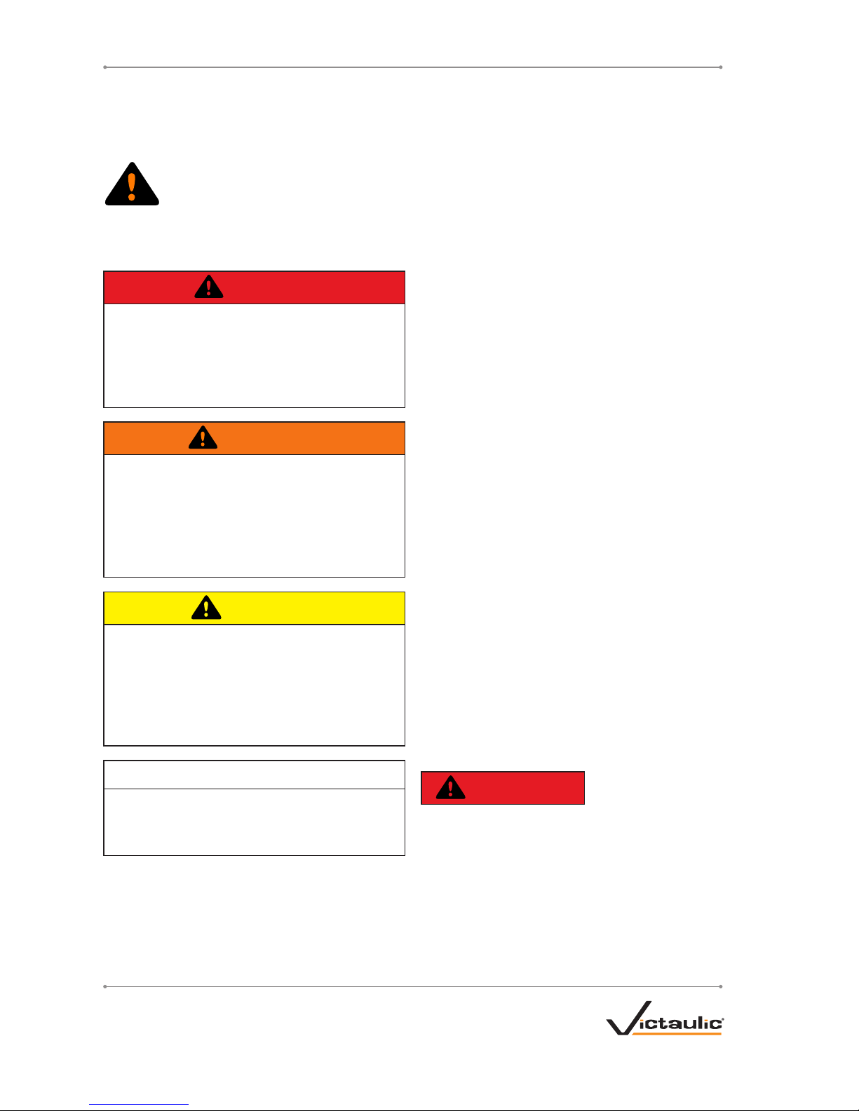
HAZARD IDENTIFICATION
Definitions for identifying the various hazard
levels are provided below.
This safety alert symbol indicates
important safety messages. When
you see this symbol, be alert to the
possibility of personal injury.
Carefully read and fully understand the message
that follows.
DANGER
• The use of the word “DANGER” identifies
an immediate hazard with a likelihood
of death or serious personal injury if
instructions, including recommended
precautions, are not followed.
WARNING
• The use of the word “WARNING”
identifies the presence of hazards
or unsafe practices that could result
in death or serious personal injury if
instructions, including recommended
precautions, are not followed.
CAUTION
• The use of the word “CAUTION”
identifies possible hazards or unsafe
practices that could result in personal
injury and product or property damage
if instructions, including recommended
precautions, are not followed.
NOTICE
• The use of the word “NOTICE” identifies
special instructions that are important
but not related to hazards.
OPERATOR SAFETY
INSTRUCTIONS
The RG2100 Roll Grooving Tool is designed
to be used in conjunction with a power drive,
such as the Ridgid™ Model 300 Power Drive
manufactured by Ridgid Tool Company, for the
sole purpose of grooving pipe. These instructions,
in addition to the instructions provided by the
power drive manufacturer, must be read and
understood by each operator PRIOR to working with the grooving tool. These instructions
describe safe operation of the tool, including
set up and maintenance. Each operator must
become familiar with the tool’s operations,
applications, and limitations. Particular care
should be given to reading and understanding
the dangers, warnings, and cautions described
throughout these operating instructions.
Use of these tools requires dexterity and
mechanical skills, as well as sound safety
habits. Although these tools are designed and
manufactured for safe, dependable operation,
it is difficult to anticipate all combinations of
circumstances that could result in an accident.
The following instructions are recommended for
safe operation of these tools. The operator is
cautioned to always practice “safety first”
during each phase of use, including set up
and maintenance. It is the responsibility of the
lessee or user of these tools to verify that all
operators read this manual and fully understand
the operation of these tools.
Store this manual in a clean, dry area where it
is always readily available. Additional copies of
this manual are available upon request through
Victaulic.
DANGER
1. Avoid using the tool in potentially
dangerous environments. Do not expose
the tool to rain, and do not use the tool in
damp or wet locations. Do not use the tool
on sloped or uneven surfaces. Keep the
work area well lit. Allow sufficient space to
operate the tool properly.
™ Ridgid is a registered trademark of Ridgid Tool Company
4
REV_B
TM-RG2100 / Operating and Maintenance Instructions Manual
Page 5

2. Ground the power drive to protect the
operator from electric shock. Verify
that the power drive is connected to an
internally grounded electrical source.
3. Disconnect the power cord from the
electrical source before servicing the
tool. Only authorized personnel should
perform maintenance on the tool. Always
disconnect the power cord from the
electrical source before servicing or
adjusting the tool.
WARNING
1. Prevent back injury. Always use proper
lifting techniques when handling tool
components.
2. Wear proper apparel. Do not wear loose
clothing, gloves, jewelry, or anything that
can become entangled in moving parts.
3. Wear protective items when working with
tools. Always wear safety glasses, hardhat,
foot protection, and hearing protection
(sound levels up to 99 decibels can be
produced during the grooving process).
4. Keep hands and tools away from the
power drive chuck and carriage edges
during grooving operation. Rotation of the
power drive can pinch or entangle fingers
and hands.
5. Do not reach inside pipe ends during tool
operation. Pipe edges can be sharp and
can snag hands and shirt sleeves.
6. Operate the tool only with a safety foot
switch. The power drive must be operated
with a safety foot switch that is located for
easy operator access. Never reach across
moving parts. If the tool does not contain a
safety foot switch, contact Victaulic.
7. Do not over-reach. Maintain proper balance
at all times. Verify that the safety foot switch
is easily accessible to the operator.
8. Do not make any modifications to the
tool. Do not remove any safety guarding
or any components that would affect tool
performance.
CAUTION
1. The RG2100 tool is designed ONLY for
grooving pipe sizes, materials, and wall
thicknesses as designated.
2. Inspect the equipment. Before using the
tool, check moveable parts for obstructions.
Ensure that tool components are installed
and adjusted in accordance with setup
instructions.
3. Stay alert. Do not operate the tool if you are
drowsy from medication or fatigue.
4. Keep visitors, trainees, and observers
away from the immediate work area. All
visitors should be kept a safe distance from
the equipment at all times.
5. Keep work areas clean. Keep the
work area around the tool clear of any
obstructions that could limit movement of
the operator. Clean up any spills.
6. Secure the work, machine, and
accessories. Verify that the tool is stable.
Refer to the “Tool Setup” section.
7. Support the work. Support long pipe lengths
with a pipe stand.
8. Do not force the tool. Do not force the tool
or accessories to perform any functions
beyond the capabilities described in these
instructions. Do not overload the tool.
9. Maintain tool with care. Keep the tool clean
to ensure proper and safe performance.
Follow the instructions for matching and
lubricating tool components, if applicable.
10. Use only Victaulic replacement parts
and accessories. Use of any other parts
may result in a voided warranty, improper
operation, and hazardous situations. Refer
to the “Parts Ordering Information” and
“Accessories” sections.
11. Do not remove any labels from the tool.
Replace any damaged or worn labels.
5
REV_B
TM-RG2100 / Operating and Maintenance Instructions Manual
Page 6
INTRODUCTION
NOTICE
• Drawings and/or pictures in this manual
may be exaggerated for clarity.
• The tool, along with this operating
and maintenance instructions manual,
contains trademarks, copyrights, and/or
patented features that are the exclusive
property of Victaulic Company.
The Victaulic RG2100 Roll Grooving Tool is a
portable tool used in conjunction with a power
drive for grooving pipe to be compatible with
Victaulic grooved piping products, including
1”/DN25 IGS products. The standard RG2100
tool is equipped to groove 1”/DN25 Schedule 10
and Schedule 40 carbon steel pipe to Victaulic’s
proprietary IGS groove specifications.
CAUTION
• This tool must be used ONLY for grooving
pipe with specifications that fall within
the designated parameters.
Failure to follow this instruction could
overload the tool, resulting in reduced tool
life, tool damage, or personal injury.
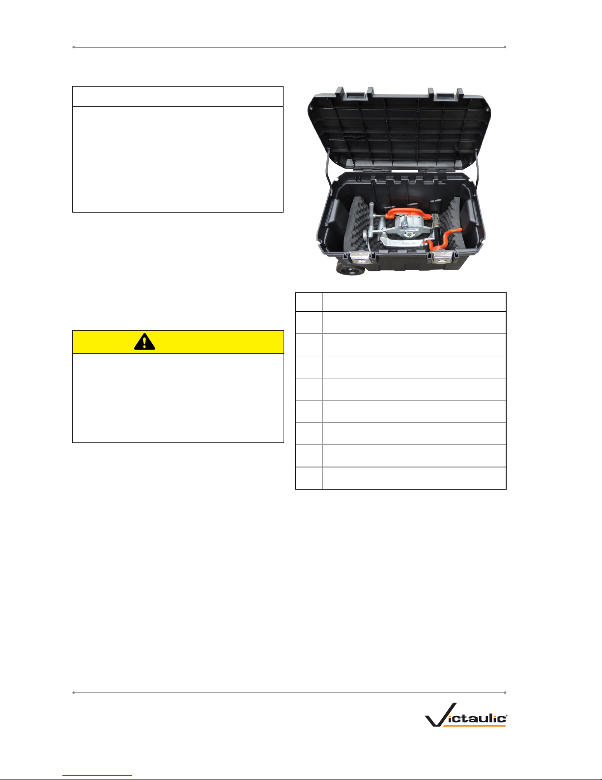
RECEIVING THE TOOL
RG2100 tools are packed individually in sturdy
containers. Upon receipt of the tool, ensure that
all necessary parts are included. If any parts
are missing, contact Victaulic.
CONTAINER CONTENTS
Qty. Description
1 Tool Head Assembly
1 Carriage Assembly
1 Pipe Cutter
1 Pipe Reamer
1 Lever Arm Assembly
1 Threading Adapter
1 Groove Confirmation Gauge
2
Operating and Maintenance Instructions Manual
RETURNING THE TOOL
Prepare tool for shipment as received. Contact
Victaulic with questions.
6
REV_B
TM-RG2100 / Operating and Maintenance Instructions Manual
Page 7
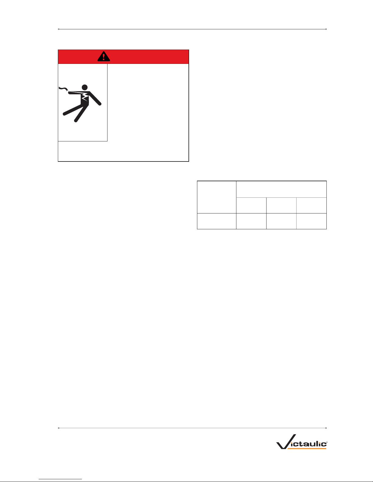
POWER REQUIREMENTS
DANGER
• To reduce the risk of
electric shock, check
the electrical source for
proper grounding.
• Before performing any
maintenance on the
tool, disconnect the
power cord from the
electrical source.
Failure to follow these instructions could
result in death or serious personal injury.
POWER DRIVE REQUIREMENTS
The RG2100 tool is designed for operation with
a power drive. The tool mounts directly onto a
Ridgid™ Model 300 Power Drive. Read and
understand the operation of the power drive
by referring to the manual provided by the
manufacturer. Contact Victaulic for information
regarding mounts for alternate power drives.
Power must be supplied to the drive motor
through a safety foot switch to ensure safe
operation. Ensure that the power drive is
grounded properly in accordance with Article
250 of the National Electrical Code and all
applicable local electrical codes.
If an extension cord is required, refer to the
“Extension Cord Requirements” section that
follows for cord sizes.
EXTENSION CORD REQUIREMENTS
When pre-wired outlets are not available and
an extension cord must be used, it is important
to use the proper cord size (i.e. Conductor Size
American Wire Gauge). Cord size selection is
based upon tool rating (amps) and cord length
(feet). Use of a cord size (gauge) thinner than
required will cause significant voltage drop
at the drive motor while the tool is operating.
Voltage drops may cause damage to the drive
motor and can result in improper tool operation.
NOTE: It is acceptable to use a cord size that is
thicker than required.
The required cord sizes for cord lengths up to
and including 100 ft /31 m are listed in the table
below. Use of extension cords longer than 100
ft/31 m must be avoided.
Drive Motor
Rating
volts/amps
Cord Lengths
feet/meters
25
8
50
15
100
31
115
15
12 gauge 12 gauge 10 gauge
7
REV_B
TM-RG2100 / Operating and Maintenance Instructions Manual
Page 8
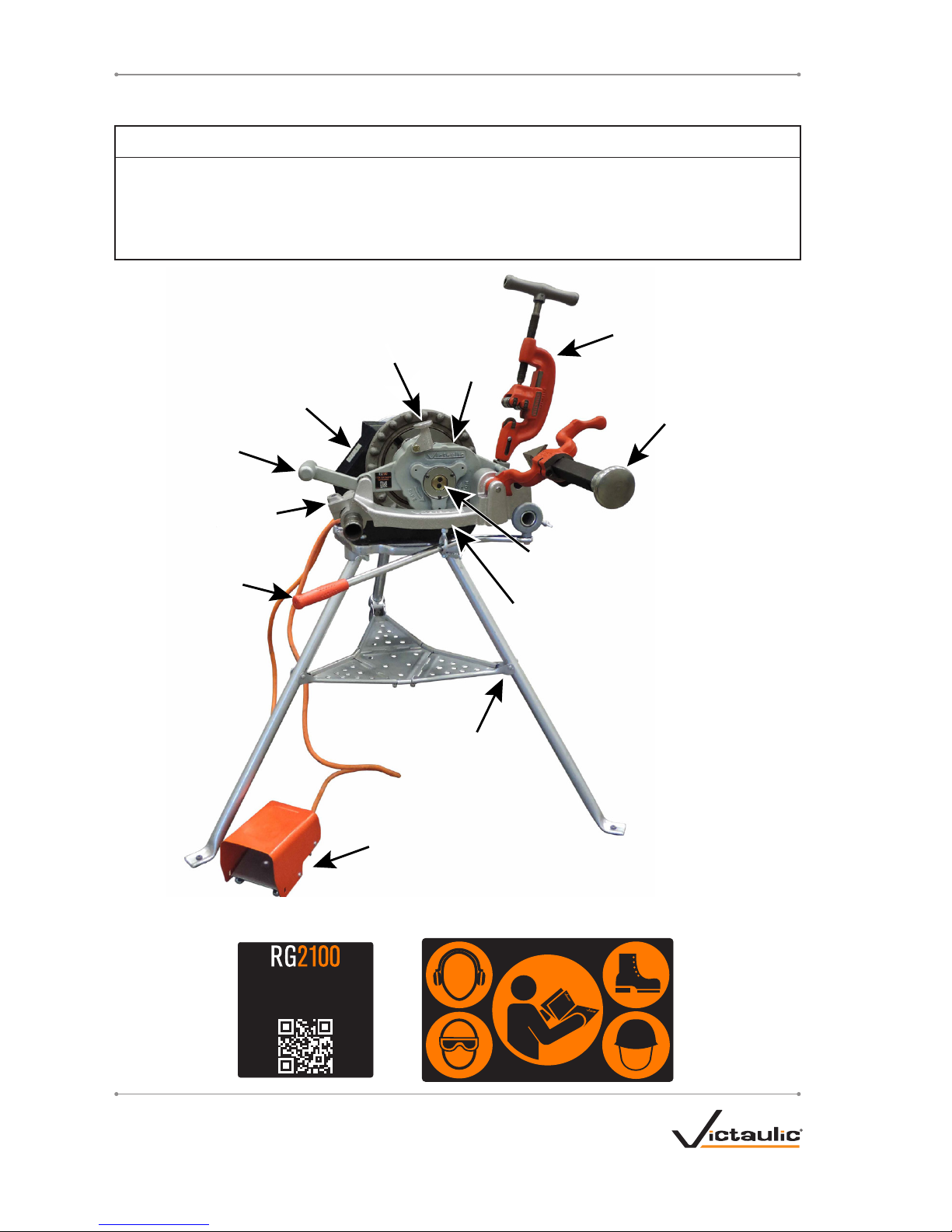
TOOL NOMENCLATURE
NOTICE
• Drawings and/or pictures in this manual may be exaggerated for clarity.
• The tool, along with this operating and maintenance instructions manual, contains
trademarks, copyrights, and/or patented features that are the exclusive property of
Victaulic.
Safety
Foot
Switch
Stand
Assembly
Power Drive
Grooving
Head
Reamer
Cutter
Actuator
Carriage Assembly
Carriage
Lever
Groover
Handle
Ready-to-Groove
Indicator
Pivot
Adapter
IMPORTANT INFORMATION LABELS PROVIDED ON THE TOOL
1"/DN25 IGS Groove
Specifications
10743 Rev. A R510743LBL
10742 Rev. A R510742LBL
8
REV_B
TM-RG2100 / Operating and Maintenance Instructions Manual
Page 9

TOOL DIMENSIONS AND SPECIFICATIONS
Tool weight is 37.5 pounds/17 kilograms. Tool weight includes the tool head assembly and carriage
only. Dimensional measurements are taken with a Ridgid™ Model 300 Power Drive.
Tool sound pressure is 93 dB(A), while tool sound power is 99 dB(A). Sound measurements are
taken with a Ridgid™ Model 300 power drive.
NOTE: Noise measurements are dependent on the power drive, and will vary based on
configuration. Always check the power drive manufacturer’s documentation for details.
52.86 in/
1343 mm
40.00 in/
1016 mm
46.16 in/
1172 mm
7.48 in/
190 mm
9.47 in/
241 mm
14.03 in/
356 mm
55.79 in/
1417 mm
38.02 in/
966 mm
37.97 in/
964 mm
35.61 in/
905 mm
9
REV_B
TM-RG2100 / Operating and Maintenance Instructions Manual
Page 10

PIPE SETUP
For proper tool operation and production of
grooves that are within Victaulic specifications,
the following guidelines must be followed.
1. Victaulic requires square-cut pipe for use with
grooved-end pipe products.
2. Raised external weld beads, seams, and
burrs must be ground flush with the pipe surface
2 inches/50 mm back from the pipe ends.
3. All coarse scale, dirt, and other foreign
material must be removed from the interior and
exterior surfaces of the pipe ends.
CAUTION
• For maximum tool life, remove foreign
material from the interior and exterior
surfaces of the pipe ends.
Foreign material may interfere with or
damage the tool, resulting in property
damage or personal injury.
4. Place pipe stands at locations appropriate for
the length of pipe to be grooved.
NOTICE
• When grooving pipe from 4.5 to 6.75
inches in length, leave 2 inches of pipe
extended from the front of the chuck.
When grooving longer pipe lengths, leave
2–4.5 inches of pipe extended from the
front of the chuck.
• Do not tighten the chuck on the first
0.5 inches of the pipe.
• When grooving pipe long enough to
extend into the rear chuck of the power
drive, tighten the rear chuck to center the
pipe length.
5. Insert the pipe into the power drive and
tighten the chuck at the proper pipe length.
While holding the pipe with one hand, use the
other hand to firmly pull the power drive hand
wheel in a counterclockwise motion until the
chuck securely grips the pipe.
WARNING
• To prevent damage to the gasket sealing
surface, pipe lengths shall be a minimum
of 4.5 inches/114 mm.
Failure to follow this instruction will cause
improper product assembly and joint failure,
resulting in serious personal injury and
property damage.
10
REV_B
TM-RG2100 / Operating and Maintenance Instructions Manual
Page 11

DRIVE SETUP
1. Plug the power drive cord into the provided
safety foot switch, as shown above. Refer to the
power drive manufacturer’s operating manual for
additional information.
2. Place the safety foot switch on the same
side of the tool as the power drive switch, with
adequate clearance for ease of use and to avoid
a tripping hazard.
WARNING
• The power drive must be operated with
a safety foot switch. If the power drive
is not supplied with a safety foot switch,
contact Victaulic.
Operating the tool without a safety foot
switch could result in serious personal
injury.
3. Turn the switch on the side of the power drive
to FWD (forward).
D
i
r
e
c
t
i
o
n
o
f
R
o
t
a
t
i
o
n
4. Depress the safety foot switch. Verify that the
pipe rotates counterclockwise when viewed from
the front power drive chuck. Remove foot from
the safety foot switch.
If the pipe rotates clockwise when viewed
from the front power drive chuck, return to the
previous step and verify the direction of the
power drive.
11
REV_B
TM-RG2100 / Operating and Maintenance Instructions Manual
Page 12

TOOL AND CARRIAGE ASSEMBLY
SETUP
WARNING
• Always use proper lifting techniques when
handling the tool and carriage assembly.
Failure to follow this instruction could result
in personal injury.
1. Using proper lifting techniques, lift the tool
and carriage assembly by the two handles with
the reamer facing toward you, as shown above.
2a. Slide the tool and carriage assembly onto
the stand assembly. The cutter should be facing
towards the power drive, as shown above.
3. Insert the carriage lever through the eye bolt.
4. Insert the lever collar over the stand arm and
tighten the wing screw to hand-tight.
5. Verify that the carriage and power drive are
secure and properly balanced.
12
REV_B
TM-RG2100 / Operating and Maintenance Instructions Manual
Page 13

CUTTING AND REAMING
OPERATION
DANGER
• To reduce the risk of
electric shock, check
the electrical source for
proper grounding.
• Before operating the tool, review the
“Operator Safety Instructions” section of
this manual.
Failure to follow these instructions could
result in death or serious personal injury.
CAUTION
• This tool must be used ONLY for
grooving pipe as designated.
Failure to follow this instruction could
overload the tool, resulting in reduced tool
life, damage to the tool, or personal injury.
Before proceeding, verify that all instructions in
the previous sections of this manual have been
followed. Read and understand the operation of
the cutter and reamer by referring to the manual
provided by the manufacturer.
Prepare for pipe ends and cut lengths of pipe
to fall during the cutting operation. Ensure that
these cuttings do not interfere with operator
movement.
1. Using the handle, bring the cutter down over
the pipe end.
2. Depress the safety foot switch to start the
power drive, then turn the handle of the cutter
in a steady motion until the pipe end is cut and
falls off. Remove foot from the safety foot switch.
3. Using the handle, lift the cutter back to its
storage position.
4. Using the handle, bring the reamer down to
the pipe end.
13
REV_B
TM-RG2100 / Operating and Maintenance Instructions Manual
Page 14

5. Push the release lever open and slide the
reamer forward until it locks into the extended
position.
6. Depress the safety foot switch to start the
power drive, then use the carriage lever to push
the reamer into the pipe end. Hold the reamer
in place for a minimum of two revolutions of the
pipe, then retract the reamer and remove foot
from the safety foot switch.
7. Retract the reamer and use the handle to lift
the reamer back to its storage position.
GROOVING OPERATION
Before proceeding, verify that all instructions in
the previous sections of this manual have been
followed.
NOTICE
• When grooving pipe from 4.5 to 6.75
inches in length, leave 2 inches of pipe
extended from the front of the chuck.
When grooving longer pipe lengths, leave
2–4.5 inches of pipe extended from the
front of the chuck.
• Do not tighten the chuck on the first
0.5 inches of the pipe.
• When grooving pipe long enough to
extend into the rear chuck of the power
drive, tighten the rear chuck to center the
pipe length.
1. Using the handle, bring the grooving head
down to rest on the pivot adapter assembly.
14
REV_B
TM-RG2100 / Operating and Maintenance Instructions Manual
Page 15

2. Using the carriage lever, push the grooving
head fully over the pipe end.
Not Ready
Ready
3. When the grooving head is pushed fully over
the pipe end, verify that the Ready-to-Groove
Indicator on the rear face of the grooving
head pops out to lie flush with the cover. This
provides visual confirmation that the tool is
unlocked and ready for grooving. If the indicator
is not flush, the tool is still locked and will not
operate.
4. Maintain grip on the carriage lever to keep
the tool in position during grooving. Depress the
safety foot switch to start the power drive, then
press and release the actuator. NOTE: Keep
all other objects away from the tool during the
grooving process.
5. Hold the grooving position until the Readyto-Groove Indicator stops rotating, signaling that
the groove is complete. Remove foot from the
safety foot switch and use the carriage lever to
pull the grooving head free from the pipe end.
6. Using the handle, lift the grooving head back
to its storage position.
15
REV_B
TM-RG2100 / Operating and Maintenance Instructions Manual
Page 16

7. Loosen the chuck to remove the pipe from
the power drive. If a pipe stand is not being
used, manually support the pipe during removal
to prevent it from falling as it separates from the
tool.
8. Disconnect the tool from the electrical source
if no additional grooving will be performed.
HEAD CHANGEOVER
The RG2100 universal carriage is easily
converted between a grooving head and a
threading head.
When a head is not in use, store it and any
applicable accessories in a clean, dry area that
is readily available to all operators.
1. With the grooving head up in the storage
position, grasp the head with both hands and
pull it towards the power drive to remove it from
the carriage. Store the grooving head in a safe
location.
2. Push the threading adapter into the socket.
16
REV_B
TM-RG2100 / Operating and Maintenance Instructions Manual
Page 17

3. Turn over the pivot adapter assembly.
4. Push the threading head onto the threading
adapter until fully seated.
5. Lower the threading head onto the pivot
adapter assembly, checking for proper
alignment.
5a. Ensure that the underside of the threading
head rests flat on the carriage.
5b. Ensure that the foot of the threading
head rests in the groove of the pivot adapter
assembly.
17
REV_B
TM-RG2100 / Operating and Maintenance Instructions Manual
Page 18

USING THE GROOVE
CONFIRMATION GAUGE
At the beginning of a grooving session, confirm
groove specifications of the first completed
piece with the provided groove confirmation
gauge.
1. Carefully check the groove diameter (“C”
dimension) by sliding the groove confirmation
gauge over the pipe groove.
If the gauge slides over the pipe groove,
the groove diameter falls within Victaulic
specifications.
If the gauge cannot fit over the pipe groove, the
groove does not meet Victaulic specifications.
GOOD
2a. Carefully check the gasket seating area (“A”
dimension) by placing the profile of the groove
against the notch in the groove confirmation
gauge.
If the pipe end falls within the right, upper edge
of the gauge notch, the “A” dimension falls
within Victaulic specifications.
BAD
2b. If the pipe end falls within the left, lower
edge of the gauge notch, the groove does not
meet Victaulic specifications.
After confirming that the groove meets
specifications, the operator may commence
grooving. It is not necessary to re-check groove
specifications unless the operator experiences
difficulty or notices unusual tool behavior.
18
REV_B
TM-RG2100 / Operating and Maintenance Instructions Manual
Page 19

MAINTENANCE
DANGER
• Before performing any
maintenance on the
tool, disconnect the
power cord from the
electrical source.
Failure to follow this
instruction could result in
death or serious personal
injury.
This section provides information about keeping
the tool in proper operating condition.
CLEANING THE GROOVING CUP
When grooving galvanized pipe, some flaking
of the galvanized coating may occur and lodge
inside the grooving cup. To minimize build-up,
apply a dry graphite spray to the grooving cup
before use with galvanized pipe.
Periodically inspect the pipe insertion area on
the front of the grooving head. If any debris
is visible inside the grooving cup, clear away
the material with a wire brush and reapply dry
graphite spray.
PARTS ORDERING
INFORMATION
When ordering parts, the following information
is required for Victaulic to process the order and
send the correct part(s). Parts can be ordered
by calling 1-800-PICK-VIC.
1. Tool Model Number
2. Tool Serial Number
3. Quantity, Item Number, Part Number, and
Description
4. Where to send the part(s) – Company
Name and Address
5. To whose attention to send the part(s) –
Person’s Name
6. Purchase Order Number
7. Billing Address
19
REV_B
TM-RG2100 / Operating and Maintenance Instructions Manual
Page 20

TROUBLESHOOTING
DANGER
• Before performing any
adjustment on the tool,
disconnect the power
cord from the electrical
source.
Failure to follow this
instruction could result in
death or serious personal
injury.
SET GROOVING HEAD TO HOME
POSITION
If the grooving head cannot be pushed onto the
pipe end, or if the grooving head is stuck on
the pipe end and cannot be removed, it may
be necessary to reset the grooving head to the
home position.
Grooving Head Cannot be Pushed Onto Pipe
End
For ease of access, put the grooving head in
the storage position while lowering the cutter
and reamer. This will provide a clear view of the
front of the grooving head.
Grooving
Cup
Roll
Edge
1. Inspect the pipe insertion area on the front
of the grooving head. If the grooving rolls
protrude past the edge of the cup, as shown
above, the grooving head must be reset to
home position.
2. To align the rolls, insert a flat-head
screwdriver into the notch that bisects the
Ready-to-Groove Indicator. Twist the screwdriver
in either direction until the indicator pops into
the locked position, so that it no longer lies
flush with the cover.
To visualize the difference between the locked
and unlocked positions of the Ready-to-Groove
Indicator, review step 3 of the “Grooving
Operation” section, on page 15.
Grooving
Cup
Roll
Edge
3. When the grooving rolls are properly aligned,
their concave edges will align with the curve of
the grooving cup, as shown above.
4. After the grooving rolls are aligned,
manually verify that the tool fits properly over
the pipe end.
20
REV_B
TM-RG2100 / Operating and Maintenance Instructions Manual
Page 21

Grooving Head Cannot be Pulled Off Pipe End
1. Loosen the power drive chuck(s) enough that
the pipe remains centered in the chuck, but the
chuck jaws allow the pipe to slide freely.
2. To align the rolls, insert a flat-head
screwdriver into the notch that bisects the
Ready-to-Groove Indicator. Twist the screwdriver
in either direction until the indicator pops into
the locked position, so that it no longer lies
flush with the cover.
To visualize the difference between the locked
and unlocked positions of the Ready-to-Groove
Indicator, review step 3 of the “Grooving
Operation” section, on page 15.
3. Once the grooving head has been reset,
tighten the power drive chuck(s) and use the
carriage lever to pull the grooving head off of
the pipe end.
21
REV_B
TM-RG2100 / Operating and Maintenance Instructions Manual
Page 22

TROUBLESHOOTING (CONTINUED)
PROBLEM POSSIBLE CAUSE SOLUTION
Pipe will not t into tool. Grooving head is not set to home position. Reset grooving head to home position. Refer to the
“Troubleshooting” section.
Pipe stops rotating during
grooving.
Pipe is slipping in the power drive chuck. Securely tighten the power drive chuck.
The circuit breaker/GFI has tripped or a fuse
has blown out on the electrical circuit that
supplies the power drive.
Test/reset the jobsite GFI/breaker, or replace the fuse. Upon
restoration of power, cut o pipe end and re-groove.
Facility has lost power. Upon restoration of facility power, cut o pipe end and re-groove.
Tool will not groove pipe. Tool is not fully pushed onto the pipe. Push the tool all the way onto the pipe.
Pipe does not extend far enough out of
the chuck.
Rechuck pipe so that the end to be grooved extends a minimum of
2 inches past the edge of the chuck.
Pipe is rotating clockwise. Reverse power drive direction to create counterclockwise rotation
of the pipe.
In the event of tool malfunction outside the scope of the troubleshooting section, contact Victaulic
Engineering Services for assistance.
22
REV_B
TM-RG2100 / Operating and Maintenance Instructions Manual
Page 23

ROLL GROOVE SPECIFICATIONS
STEEL PIPE
Size Dimensions – inches/millimeters
Nominal
Size
inches
Actual Pipe
Outside
Diameter
inches/mm
Pipe Outside Diameter Gasket Seat “A” Groove Width “B” Groove Diameter “C”
Groove
Depth
“D” (ref.)
Max. Allow.
Wall
Thick. “T”
Min. Allow.
Wall
Thick. “T”
Max.
Allow.
Flare Dia.Max. Min. Basic Max. Min. Basic Max. Min. Max. Min.
1
1.327 1.330 1. 300 0.375 0.405 0.345 0.150 0.160 0.14 0 1.190 1.170 0.063 0.133 0.109 1. 35
33.7 33.8 33.0 9.5 10.3 8.8 3.8 4 .1 3.6 30.2 29.7 1.6 3.4 2.8 34.3
A B
C
OD
D
T
23
REV_B
TM-RG2100 / Operating and Maintenance Instructions Manual
Page 24

UPDATED 7/2017
TM-RG2100 10659 REV B RM00RG2100
VICTAULIC IS A REGISTERED TRADEMARK OF VICTAULIC COMPANY AND/OR ITS AFFILIATED
ENTITIES IN THE UNITED STATES AND/OR OTHER COUNTRIES.
© 2017 VICTAULIC COMPANY. ALL RIGHTS RESERVED.
OPERATING AND MAINTENANCE INSTRUCTIONS MANUAL
RG2100 Roll Grooving Tool
TM-RG2100
 Loading...