

Page 1

OPERATING AND MAINTENANCE INSTRUCTIONS MANUAL
PC3110 Cut and Mark Tool
WARNING
Original Instructions
WARNING
Failure to follow instructions and warnings could result in death,
serious personal injury, property damage, and/or product damage.
• Before operating or servicing any pipe preparation tools, read all
instructions in this manual and all warning labels on the tool.
• Wear safety glasses, hardhat, foot protection, and hearing
protection while working around this tool.
• Save this operating and maintenance manual in a place
accessible to all operators of the tool.
If you need additional copies of any literature, or if you have questions concerning the safe
and proper operation of this tool, contact Victaulic, P.O. Box 31, Easton, PA 18044-0031,
Phone: 1-800-PICK-VIC, E-Mail: pickvic@victaulic.com.
REV_B
TM-PC3110
Page 2

Page 3

TABLE OF CONTENTS
Hazard Identification ................. 4
Operator Safety Instructions ............ 4
Introduction ....................... 6
Receiving The Tool ...................6
Container Contents ...................6
Returning The Tool ...................6
Power Requirements ................. 7
Power Drive Requirements..............7
Extension Cord Requirements ...........7
Tool Nomenclature................... 8
Tool Dimensions and Specifications ...... 9
Pipe Setup ........................10
Drive Setup........................10
Tool Setup ........................11
Cutting Operation ...................12
Storage Operation ...................14
Maintenance .......................14
Parts Ordering Information .............14
Accessories........................15
Troubleshooting.....................16
Knurling/Marking Specifications . . . . . . . . .17
EC Declaration of Incorporation .........18
3
REV_B
TM-PC3110 / Operating and Maintenance Instructions Manual
Page 4

HAZARD IDENTIFICATION
Definitions for identifying the various hazard
levels are provided below.
This safety alert symbol indicates
important safety messages. When
you see this symbol, be alert to the
possibility of personal injury.
Carefully read and fully understand the message
that follows.
DANGER
• The use of the word “DANGER” identifies
an immediate hazard with a likelihood
of death or serious personal injury if
instructions, including recommended
precautions, are not followed.
WARNING
• The use of the word “WARNING”
identifies the presence of hazards
or unsafe practices that could result
in death or serious personal injury if
instructions, including recommended
precautions, are not followed.
CAUTION
• The use of the word “CAUTION”
identifies possible hazards or unsafe
practices that could result in personal
injury and product or property damage
if instructions, including recommended
precautions, are not followed.
NOTICE
• The use of the word “NOTICE” identifies
special instructions that are important
but not related to hazards.
OPERATOR SAFETY
INSTRUCTIONS
The PC3110 Cut and Mark Tool is designed to
be used, in conjunction with a power drive, for
the sole purpose of preparing plain-end pipe
for joining. These instructions, in addition to
the instructions provided by the power drive
manufacturer, must be read and understood
by each operator PRIOR to working with the
tool. These instructions describe safe operation
of the tool, including set up and maintenance.
Each operator must become familiar with the
tool’s operations, applications, and limitations.
Particular care should be given to reading and
understanding the dangers, warnings, and
cautions described throughout these operating
instructions.
Use of this tool requires dexterity and
mechanical skills, as well as sound safety
habits. Although these tools are designed and
manufactured for safe, dependable operation,
it is difficult to anticipate all combinations of
circumstances that could result in an accident.
The following instructions are recommended
for safe operation of this tool. The operator is
cautioned to always practice “safety first”
during each phase of use, including set up
and maintenance. It is the responsibility of the
lessee or user of this tool to ensure that all
operators read this manual and fully understand
the operation of this tool.
Store this manual in a clean, dry area where
it is always readily available. Additional copies
of this manual are available upon request
through Victaulic, or can be downloaded at
victaulic.com.
DANGER
1. Avoid using the tool in potentially
dangerous environments. Do not expose
the tool to rain, and do not use the tool in
damp or wet locations. Do not use the tool
on sloped or uneven surfaces. Keep the
work area well lit. Allow sufficient space to
operate the tool properly.
4
REV_B
TM-PC3110 / Operating and Maintenance Instructions Manual
Page 5

2. Ground the power drive to protect the
operator from electric shock. Verify
that the power drive is connected to an
internally grounded electrical source.
3. Disconnect the power cord from the
electrical source before servicing the
tool. Only authorized personnel should
perform maintenance on the tool. Always
disconnect the power cord from the
electrical source before servicing or
adjusting the tool.
WARNING
1. Prevent back injury. Always use proper
lifting techniques when handling tool
components.
2. Wear proper apparel. Do not wear loose
clothing, gloves, jewelry, or anything that
can become entangled in moving parts.
3. Wear protective items when working with
tools. Always wear safety glasses, hardhat,
and foot protection.
4. Keep hands and tools away from the
power drive chuck and carriage edges
during operation. Rotation of the power
drive can pinch or entangle fingers and
hands.
5. Do not reach inside pipe ends during tool
operation. Pipe edges can be sharp and
can snag hands and shirt sleeves.
6. Operate the tool only with a safety foot
switch. The power drive must be operated
with a safety foot switch that is located for
easy operator access. Never reach across
moving parts.
7. Do not over-reach. Maintain proper
balance at all times. Ensure that the safety
foot switch is easily accessible to the
operator.
8. Do not make any modifications to the
tool. Do not remove any safety guarding
or any components that would affect tool
performance.
CAUTION
1. The PC3110 tool is designed ONLY for
preparing pipe sizes, materials, and wall
thicknesses as designated.
2. Inspect the equipment. Before using
the tool, check moveable parts for
obstructions. Ensure that tool components
are installed and adjusted in accordance
with setup instructions. Ensure that tool
components are stable and secure.
3. Stay alert. Do not operate the tool if you
are drowsy from medication or fatigue.
4. Keep visitors, trainees, and observers
away from the immediate work area. All
visitors should be kept a safe distance from
the equipment at all times.
5. Keep work areas clean. Keep the
work area around the tool clear of any
obstructions that could limit movement of
the operator. Clean up any spills on the
floor to prevent slips or falls.
6. Secure the work, tool, and accessories.
Ensure that the tool is stable. Refer to the
“Tool Setup” section.
7. Support the work. Support long pipe
lengths with a pipe stand.
8. Do not force the tool. Do not force the tool
or accessories to perform any functions
beyond the capabilities described in these
instructions. Do not overload the tool.
9. Maintain tool with care. Keep the
tool clean to ensure proper and safe
performance. Follow the instructions for
matching and lubricating tool components,
if applicable.
10. Use only Victaulic replacement parts
and accessories. Use of any other parts
may result in a voided warranty, improper
operation, and hazardous situations. Refer
to the “Parts Ordering Information” section.
11. Do not remove any labels from the tool.
Replace any damaged or worn labels.
5
REV_B
TM-PC3110 / Operating and Maintenance Instructions Manual
Page 6
INTRODUCTION
NOTICE
• Drawings and/or pictures in this manual
may be exaggerated for clarity.
• The tool, along with this operating
and maintenance instructions manual,
contains trademarks, copyrights, and/or
patented features that are the exclusive
property of Victaulic Company.
The Victaulic PC3110 Cut and Mark Tool is a
portable tool used in conjunction with a power
drive for preparing plain-end pipe to be joined
with Victaulic Installation-Ready™ products. The
standard PC3110 tool is equipped to cut and
mark ½ – 2 inch Schedule 10 through Schedule
80 carbon steel pipe.
CAUTION
• This tool must be used ONLY for
preparing pipe with specifications that
fall within the designated parameters.
Failure to follow this instruction could
overload the tool, resulting in reduced tool
life, tool damage, or personal injury.
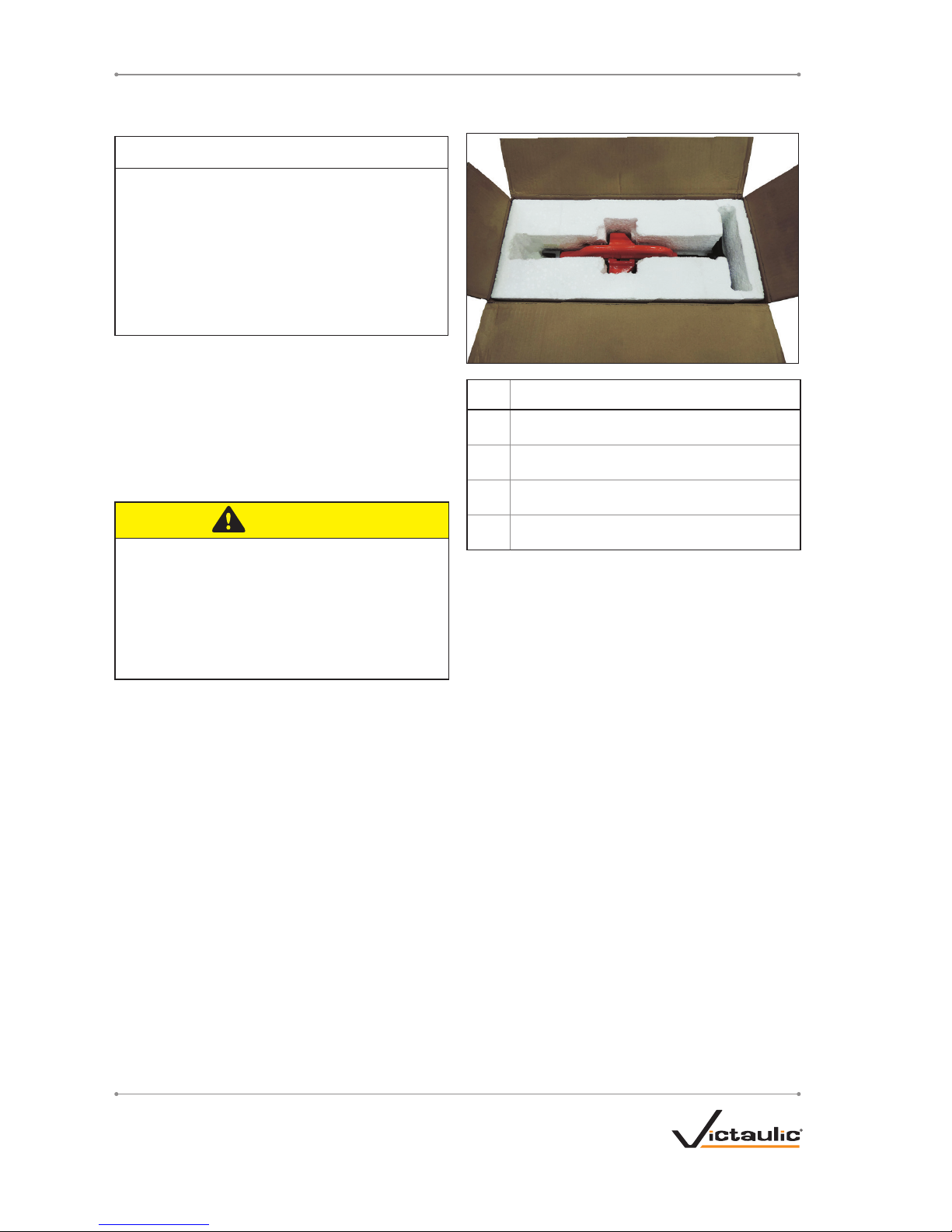
RECEIVING THE TOOL
PC3110 tools are packed individually in
cardboard boxes. Upon receipt of the tool,
ensure that all necessary parts are included. If
any parts are missing, contact Victaulic.
CONTAINER CONTENTS
Qty. Description
1 PC3110 Cut and Mark Tool
1 Hinge Pin
5 Cutting Wheel
2
Operating and Maintenance Instructions Manual
RETURNING THE TOOL
Prepare tool for shipment as received. Contact
Victaulic with questions.
6
REV_B
TM-PC3110 / Operating and Maintenance Instructions Manual
Page 7

POWER REQUIREMENTS
DANGER
• To reduce the risk of
electric shock, check
the electrical source for
proper grounding.
• Before performing any
maintenance on the
tool, disconnect the
power cord from the
electrical source.
Failure to follow these instructions could
result in death or serious personal injury.
POWER DRIVE REQUIREMENTS
The PC3110 tool is designed for operation
with a power drive. Read and understand the
operation of the power drive by referring to the
manual provided by the manufacturer.
Power must be supplied to the drive motor
through a safety foot switch to ensure safe
operation. Ensure that the power drive is
grounded properly in accordance with Article
250 of the National Electrical Code and all
applicable local electrical codes.
If an extension cord is required, refer to the
“Extension Cord Requirements” section that
follows for cord sizes.
EXTENSION CORD REQUIREMENTS
When pre-wired outlets are not available and
an extension cord must be used, it is important
to use the proper cord size (i.e. Conductor Size
American Wire Gauge). Cord size selection is
based upon tool rating (amps) and cord length
(feet). Use of a cord size (gauge) thinner than
required will cause significant voltage drop
at the drive motor while the tool is operating.
Voltage drops may cause damage to the drive
motor and can result in improper tool operation.
NOTE: It is acceptable to use a cord size that is
thicker than required.
The required cord sizes for cord lengths up to
and including 100 ft /31 m are listed in the table
below. Use of extension cords longer than 100
ft/31 m must be avoided.
Drive Motor
Rating
volts/amps
Cord Lengths
feet/meters
25
8
50
15
100
31
115
15
12 gauge 12 gauge 10 gauge
7
REV_B
TM-PC3110 / Operating and Maintenance Instructions Manual
Page 8

TOOL NOMENCLATURE
NOTICE
• Drawings and/or pictures in this manual may be exaggerated for clarity.
• The tool, along with this operating and maintenance instructions manual, contains
trademarks, copyrights, and/or patented features that are the exclusive property of
Victaulic.
Handle
Cutting
Wheel
Knurled
Rolls
IMPORTANT INFORMATION LABELS PROVIDED ON THE TOOL
PINCH
POINT
R511753LBL
11753 Rev. A
11752 Rev. A R511752LBL
8
REV_B
TM-PC3110 / Operating and Maintenance Instructions Manual
Page 9

TOOL DIMENSIONS AND SPECIFICATIONS
Tool weight is 10.3 pounds/4.7 kilograms. Tool weight includes the tool head assembly only.
7.1 in
180 mm
4.6 in
117 mm
4.4 in
113 mm
17.0 in
432 mm
9
REV_B
TM-PC3110 / Operating and Maintenance Instructions Manual
Page 10

PIPE SETUP
For proper tool operation and production of pipe
ends that are within Victaulic specifications, the
following guidelines must be followed.
1. Victaulic requires square-cut pipe for use with
plain-end pipe products.
2. Raised external weld beads, seams, and
burrs must be ground flush with the pipe surface
2 inches/50 mm back from the pipe ends.
3. All coarse scale, dirt, and other foreign
material must be removed from the interior and
exterior surfaces of the pipe ends.
CAUTION
• For maximum tool life, remove foreign
material from the interior and exterior
surfaces of the pipe ends.
Foreign material may interfere with or
damage the tool, resulting in property
damage or personal injury.
4. Place pipe stands at locations appropriate for
the length of pipe to be cut.
NOTICE
• The pipe must extend a minimum of
5 inches/127 mm from the front of the
chuck for proper tool operation.
• When marking pipe long enough to
extend into the rear chuck of the power
drive, tighten the rear chuck to center the
pipe length.
• When marking pipe 3 feet/0.9 meters
or longer, a pipe stand must be used to
support the pipe.
5. Insert the pipe into the power drive and
tighten the chuck at the proper pipe length.
While holding the pipe with one hand, use the
other hand to firmly pull the power drive hand
wheel in a counterclockwise motion until the
chuck securely grips the pipe.
DRIVE SETUP
1. Plug the power drive cord into a safety foot
switch, as shown above. Refer to the power
drive manufacturer’s operating manual for
additional information.
2. Place the safety foot switch on the same
side of the tool as the power drive switch, with
adequate clearance for ease of use and to avoid
a tripping hazard.
10
REV_B
TM-PC3110 / Operating and Maintenance Instructions Manual
Page 11

WARNING
• The power drive must be operated with a
safety foot switch.
Operating the tool without a safety foot
switch could result in serious personal injury.
3. Turn the switch on the side of the power drive
to FWD (forward).
C
o
r
r
e
c
t
D
i
r
e
c
t
i
o
n
4. Depress the safety foot switch. Ensure that
the pipe rotates counterclockwise when viewed
from the front power drive chuck. Remove foot
from the safety foot switch.
If the pipe rotates clockwise when viewed
from the front power drive chuck, return to the
previous step and verify the direction of the
power drive.
TOOL SETUP
WARNING
• Always use proper lifting techniques when
handling the tool.
Failure to follow this instruction could result
in personal injury.
1. Place the cutter over the bracket on the
carriage assembly.
11
REV_B
TM-PC3110 / Operating and Maintenance Instructions Manual
Page 12

2. Insert the hinge pin into the bracket slot.
3. Using a hammer or mallet, gently tap the
hinge pin into the bracket slot until it is secure.
Do not force the hinge pin farther into the slot
than is necessary to secure the tool.
CUTTING OPERATION
DANGER
• To reduce the risk of
electric shock, check
the electrical source for
proper grounding.
• Before operating the tool, review the
“Operator Safety Instructions” section of
this manual.
Failure to follow these instructions could
result in death or serious personal injury.
CAUTION
• This tool must be used ONLY for
preparing pipe as designated.
Failure to follow this instruction could
overload the tool, resulting in reduced tool
life, damage to the tool, or personal injury.
Before proceeding, ensure that all instructions in
the previous sections of this manual have been
followed.
Prepare for pipe ends and cut lengths of pipe
to fall during the cutting operation. Ensure that
these cuttings do not interfere with operator
movement.
1. Using the handle, bring the cutter down over
the pipe end.
12
REV_B
TM-PC3110 / Operating and Maintenance Instructions Manual
Page 13

2. Ensure that the two knurled rolls are centered
on the pipe.
3. Depress the safety foot switch to start the
power drive, then turn the handle of the cutter
in a steady motion until the pipe end is cut and
falls off. Remove foot from the safety foot switch.
4. Using the handle, lift the cutter back to its
storage position.
5. Inspect the finished pipe end. Ensure that
the knurling is clearly defined and is consistent
around the entire OD of the pipe.
13
REV_B
TM-PC3110 / Operating and Maintenance Instructions Manual
Page 14

STORAGE OPERATION
If the cut and mark tool will be stored on the
carriage assembly when not in use, it can be
rotated to provide additional room for alternate
carriage accessories.
1. To turn the cutter for carriage storage, lift the
body of the cutter away from the shaft.
2. Twist the body of the cutter 90 degrees
counterclockwise so that the knurled rolls face
the front of the carriage, then lower the body of
the cutter back down towards the shaft.
MAINTENANCE
DANGER
• Before performing any
maintenance on the
tool, disconnect the
power cord from the
electrical source.
Failure to follow this
instruction could result in
death or serious personal
injury.
This section provides information about
keeping the tool in proper operating condition.
Replacement parts must be ordered from
Victaulic to ensure proper and safe operation
of the tool. See the “Accessories” section for
replacement part kits.
The tool must be cleaned after use to remove
dust and debris from all components. Pay
particular attention to the knurled rolls, where
debris can build up and interfere with pipe
marking. If any debris is visible on the knurled
rolls, clear away the material with a wire brush.
PARTS ORDERING
INFORMATION
When ordering parts, the following information
is required for Victaulic to process the order and
send the correct part(s). Parts can be ordered
by calling 1-800-PICK-VIC.
1. Tool Model Number
2. Tool Serial Number
3. Quantity, Item Number, Part Number, and
Description
4. Where to send the part(s) – Company
Name and Address
5. To whose attention to send the part(s) –
Person’s Name
6. Purchase Order Number
7. Billing Address
14
REV_B
TM-PC3110 / Operating and Maintenance Instructions Manual
Page 15

ACCESSORIES
KNURLED ROLLS KIT
3
4
1
5
2
Item
No. Part No. Qty. Description
1
R000311KRL
2 C Clip
2 4 Bushing
3 1
Knurled Roll with Line
Takeout
4 1 Knurled Roll
5 2 Roll Shaft
CUTTING WHEEL KIT
12
13
11
Item
No. Part No. Qty. Description
11
R000311CWL
1 C Clip
12 1 Cutting Wheel
13 1 Cutting Wheel Shaft
CUTTING WHEELS
Item
No. Part No. Qty. Description
12 R000311WHL 5 Cutting Wheel
15
REV_B
TM-PC3110 / Operating and Maintenance Instructions Manual
Page 16

TROUBLESHOOTING
PROBLEM POSSIBLE CAUSE SOLUTION
Pipe stops rotating during pipe
preparation.
Pipe is slipping in the power drive chuck. Securely tighten the power drive chuck.
The circuit breaker/GFI has tripped or a fuse
has blown out on the electrical circuit that
supplies the power drive.
Test/reset the jobsite GFI/breaker, or replace the fuse. Upon
restoration of power, resume pipe preparation.
Facility has lost power. Upon restoration of facility power, resume pipe preparation.
Tool will not cut pipe. Tool is not fully pushed onto the pipe. Push the tool all the way onto the pipe.
Pipe does not extend far enough out of
the chuck.
Rechuck pipe so that the end to be prepared extends a minimum of
5 inches/127 mm past the edge of the chuck.
Knurled rolls are not centered on pipe. Center knurled rolls on the pipe.
Cutting wheel is dull. Replace cutting wheel.
Pipe markings are not clearly
dened.
Knurling on rolls is lled with debris. Clean knurling surface with a wire brush.
Knurled rolls are worn. Replace knurled rolls.
In the event of tool malfunction outside the scope of the troubleshooting section, contact Victaulic for
assistance.
16
REV_B
TM-PC3110 / Operating and Maintenance Instructions Manual
Page 17

KNURLING/MARKING SPECIFICATIONS
PLAIN-END IR FOR STEEL PIPE
1.415 in
2X
.224 in
5.69 mm
1.040 in
26.42 mm
35.94 mm
½ inch – 1 ¼ inch insertion depth aligns with the first knurling
1 ½ inch – 2 inch insertion depth aligns with the second knurling
17
REV_B
TM-PC3110 / Operating and Maintenance Instructions Manual
Page 18

MD_DoI_RGT_009_042418_en.docx
VICTAULIC IS A REGISTERED TRADEMARK OF VICTAULIC COMPANY. ©2013 VICTAULIC COMPANY. ALL RIGHTS RESERVED.
EC DECLARATION OF INCORPORATION
In Accordance with the Machinery Directive 2006/42/EC
Victaulic Company, headquartered at 4901 Kesslersville Road, Easton, PA 18040, USA, hereby declares
that the machinery listed below complies with the essential safety requirements of the Machinery
Directive, 2006/42/EC.
Product Model: PC3110
Serial No. : Refer to Machinery Nameplate
Product Description: Portable pipe cutting and marking tool
Conformity Assessment: 2006/42/EC, Annex I
Technical Documentation: The relevant technical documentation prepared in
accordance with Annex VII (B) of the Machinery Directive
2006/42/EC, will be made available upon request to the
governing authorities.
Compatible Power Drives: When installed with the following power drive unit,
having an appropriate EC Declaration of Conformity in
accordance with Annex II (A) of the Directive
2006/42/EC, the PC3110 model listed above may be
commissioned for the full intended purpose:
Ridgid 300
Authorized Representative: Victaulic Company
c/o Victaulic Europe BVBA
Prijkelstraat 36
9810, Nazareth
Belgium
Signed for and on behalf of Victaulic Company,
Mr. Len R. Swantek
Director – Global Regulatory Compliance
Machinery Manufacturer Representative
Place of Issue: Easton, Pennsylvania, USA
Date of Issue: April 24, 2018
Page 19

This page intentionally blank
19
REV_B
TM-PC3110 / Operating and Maintenance Instructions Manual
Page 20

UPDATED 04/2018
TM-PC3110 11646 REV B RM00PC3110
VICTAULIC IS A REGISTERED TRADEMARK OF VICTAULIC COMPANY AND/OR ITS AFFILIATED
ENTITIES IN THE UNITED STATES AND/OR OTHER COUNTRIES.
© 2018 VICTAULIC COMPANY. ALL RIGHTS RESERVED.
OPERATING AND MAINTENANCE INSTRUCTIONS MANUAL
PC3110 Cut and Mark Tool
TM-PC3110
 Loading...