

Victaulic KOIL-KIT 799 Series, KOIL-KIT 79V Series, KOIL-KIT 79B Series, KOIL-KIT 79A Series Installation And Maintenance Instructions Manual
Page 1
I-KOIL.KITINSTALLATION AND MAINTENANCE INSTRUCTIONS
KOIL-KIT™ Coil Pack – Series 799, Series 79V with ATC Valve,
Series 79B with Bypass, and Series 79A with Bypass and ATC Valve
WARNING
• Read and understand all instructions before attempting to install
any Victaulic piping products.
• Depressurize and drain the piping system before attempting
to install, remove, adjust, or maintain any Victaulic piping
products.
• Wear safety glasses, hardhat, and foot protection.
Failure to follow these instructions could result in death or serious
personal injury and property damage.
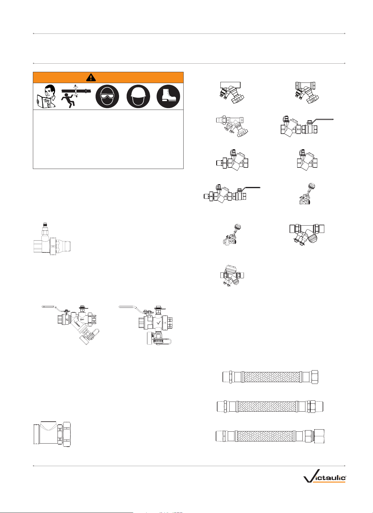
RECEIVING THE SHIPMENT
Victaulic® KO IL-K I T™ Coil Packs are a pre-packaged and labeled system
designed to improve efficiency of hooking up HVAC coils. Upon receipt
of the shipment, ensure that the kit is the correct one for the coil being
installed. If any components are damaged or missing, contact Victaulic.
Union Port Fitting with Air Vent
The Series 78U Union Port Fitting with Air Vent
can be supplied to accommodate up to a threesize reduction. Connections can be configured,
as listed below:
• Sweat x Sweat Union (Two Size Reductions)
• Sweat x Female Thread Union (Two Size Reductions)
• Sweat x Male Thread Union (Three Size Reductions)
• Female Thread x Sweat Union (Two Size Reductions)
• Female Thread x Female Thread Union (Two Size Reductions)
• Female Thread x Male Thread Union (Three Size Reductions)
“Y” Strainer/Ball Valve Combination or “T” Ball Valve
SERIES 78Y SERIES 78T
The Series 78Y Strainer/Ball Valve Combination or Series 78T Ball
Valve can accommodate up to a two-size reduction from inlet to outlet.
Connections can be configured, as listed below:
• Sweat x Sweat Union (Two Size Reductions)
• Sweat x Female Thread Union (Two Size Reductions)
• Sweat x Male Thread Union (Three Size Reductions)
• Female Thread x Sweat Union (Two Size Reductions)
• Female Thread x Female Thread Union (Two Size Reductions)
• Female Thread x Male Thread Union (Three Size Reductions)
Bypass Tee Option
The Bypass Tee option connects to the Series 78Y
Strainer/Ball Valve Combination or Series 78T Ball
Valve for hookup of the Series 79B KOIL-KIT™ Coil
Pack with Bypass or Series 79A KOIL-KIT™ Coil
Pack with Bypass and ATC Valve.
Balancing Valves
Series 78 6 Balancing Valve
(Submittal D ocument 0 8.16)
Series 78 K Balancing Valve
(Submittal D ocument 0 8.16)
Series 76K Au tomatic Balan cing Valve
(Submittal D ocument 0 8.34)
Series 76 V Automatic Bal ancing Valve
(Submittal D ocument 0 8.34)
Series 7FP Pressure-Indep endent Combined
Balancing and Control Valve with Independent
EQM (Equal Percent age Value) Characteristics
(Submittal D ocument 0 8.53)
Series TCP Pressure-Independent
Balancing and Control Valve
(Submittal D ocument 0 8.39)
Series 787 B alancing Valve
(Submittal D ocument 0 8.16)
Series 76B Au tomatic Balan cing Valve
(Submittal D ocument 0 8.34)
Series 76T Automatic Bal ancing Valve
(Submittal D ocument 0 8.34)
Series 7FC C ombined Balancing and Contro l
Valve with Indep endent EQM
(Equal Percentage Value) Characteristics
(Submittal D ocument 0 8.52)
Series TC /TCM TBV Terminal Balancing
and Control Valves
(Submittal D ocument 0 8.38)
Manual or Automatic Air Bleed Valve
The manual or automatic air bleed valve is rated to 250 psi/17 Bar and
provides a means of bleeding off trapped air when used with the Series
78U Union Port Fitting, Series 78Y Strainer/Ball Valve Combination,
Series 78T Ball Valve, or Series 78K Balancing Valve.
Coil Hoses
Coil hoses are available in 1-foot/0.3-meter, 2-foot/0.6-meter, or
3-foot/0.9-meter lengths for connecting to the inlet and outlet of the coil
and are available with the following union ends:
Male Coupling x Female Union End
Male Coupling x Male Swivel Union
Male Coupling x Female Union End with Adapter
REV_F
I-KOIL.KIT_1
Page 2
I-KOIL.KIT / KO I L-K IT™ Coil Pack / Installation and Maintenance Instructions
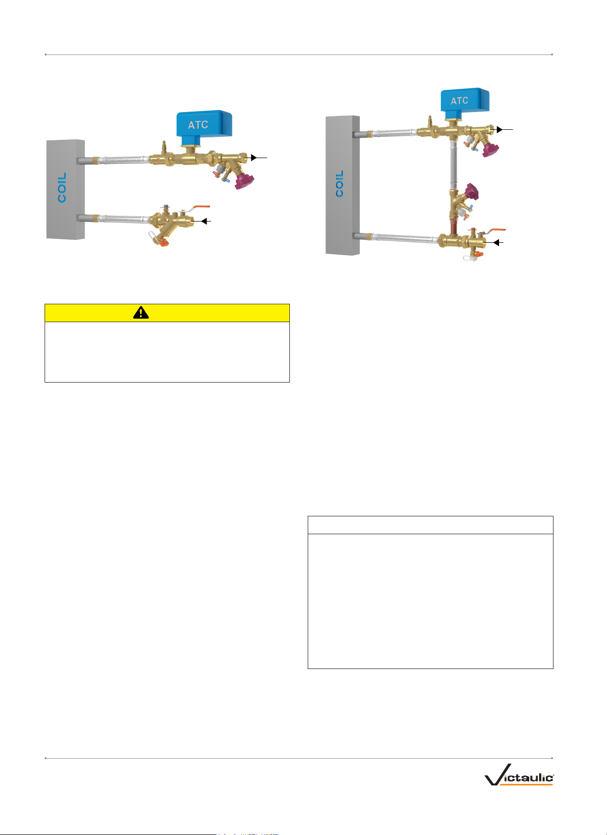
EXAMPLE COIL COMPONENT ASSEMBLY DRAWING
NOTE: THE FIGURES SHOWN BELOW ARE FOR REFERENCE ONLY AND ILLUSTRATE T YPICAL 2-WAY AND 3-WAY CONFIGURATIONS.
(By Others)
(By Others)
Hose (Optional)
Series 78U
Series 78K
Hose (Optional)
SUPPLY
Series 78Y
RETURN
SWEAT CONNECTIONS
CAUTION
• Valves must be in the fully-open position before attempting to
solder the ends.
Soldering a valve in the closed or partially-open position may
cause damage to internal components, resulting in valve leakage
and property damage.
Make sure the valve is installed in the correct direction of flow (refer
to applicable flow direction arrow on the valve body) and that the
valve is in the fully-open position before attempting to solder the ends.
Connections must be soft soldered with 95/5 (95% tin, 5% antimony)
type solder. The valve body must be heat sinked with a wet cloth
or putty at the closest joint to protect internal components, and the
flame must be directed away from the center of the valve body. DO
NOT exceed the temperature rating of the valve (250°F/121°C). Valve
bodies must be allowed to cool to room temperature before attempting
operation.
THREADED CONNECTIONS
Make sure all threaded connections are clean and free of any burrs.
Apply PTFE thread sealant tape or pipe dope to the external threads
of all threaded pipe connections. DO NOT use a combination of PTFE
thread sealant tape and pipe dope. DO NOT get any tape, dope, or
other foreign material into the flow path. NOTE FOR CONNECTING
TO FEMALE NPSM SWIVEL ENDS OF COIL HOSES: DO NOT use
PTFE thread sealant tape or pipe dope on any NPT threads connecting
into the female NPSM swivel end. Tape or dope may prevent proper
tightening of the threaded connection, reducing gasket compression.
UNION-TYPE ADAPTERS/CONNECTIONS
The o-rings in union-type adapters/connections must be lubricated
with Victaulic Lubricant or silicone to prevent the o-ring from pinching
or tearing during installation. Tighten union-type adapters/connections
hand-tight, then apply an additional quarter turn. DO NOT over-tighten
the connection.
Hose (Optional)
Hose (Optional)
Series 78U
Hose
(Optional)
Bypass
Valve
(Optional)
Series 78T
with Bypass Tee
Option
Series 787
RETURN
SUPPLY
COIL COMPONENT INSTALLATION
1. Connect the supply side of the Series 78Y Strainer/Ball Valve
Combination or Series 78T Ball Valve to the feed pipe via standard
threading or sweating practices, as described previously. Make
sure the applicable flow direction arrow on the valve body is facing
the direction of flow and that the valve body is rotated to the
desired position. NOTE: For effective operation, air vents must be
positioned at the highest possible location and must point upward.
2. If using coil hoses, make the connection to the coil first. Connect
the coil hose to the Series 78Y or Series 78T outlet union joint.
Ensure the o-ring is in place on the Series 78Y or Series 78T body.
Apply a thin coat of Victaulic Lubricant or silicone to the o-ring.
Refer to the “Coil Hose Installation” section for details on bend
radius specifications and additional installation requirements.
3. Connect the outlet of the balancing valve to the return pipe via
standard threading or sweating practices. NOTE: In order to obtain
accurate differential pressure measurements, turbulence should
be minimized. Refer to the installation instructions supplied with
the applicable valve.
4. Connect the coil hose (if applicable) to the inlet of the Series 78U
Union Port Fitting.
NOTICE
• Generally, between the male union outlet of the Series 78U and
the inlet of the balancing valve, there is a customer-specified
Automatic Temperature Control (ATC) Valve.
• Ensure that the ATC valve contains the correct inlet and outlet
sizes. Cutout lengths, etc. will need to be determined on a
case-by-case basis, depending on the type of ATC valve being
installed.
• If ATC valves are sent to Victaulic for inclusion in kits, verify that
the appropriate ATC valve is installed for the particular hook-up
to ensure proper design flows and performance.
• Refer to the instructions supplied with the ATC valve for
complete installation and maintenance requirements.
I-KOIL.KIT_ 2
REV_F
Page 3

I-KOIL.KIT / KO I L-K IT™ Coil Pack / Installation and Maintenance Instructions
NPT Male
COIL HOSE INSTALLATION
CAUTION
• DO NOT introduce chemicals into the system without verifying
compatibility with the EPDM material of the coil hoses.
Failure to follow this instruction could cause damage to the coil
hose, resulting in property damage.
Straight Pipe
NPSM Female
Swivel End
Compression
Gasket
Ferrule
Size Inlet Options – inches
Female
NPSM
Nominal ID
inches
Male End
Thread
Swivel
Union inches/mm psi/Bar
½ x ½NPT ½
¾ x ¾ NPT ¾
1 x 1 NPT 1
1¼ x 1 ¼ NPT 1 ¼
1½ x 1 ½ NPT 1 ½
2 x 2 NPT 2
The minimum temperature rating for coil hoses is 5°F/-15°C.
The maximum temperature rating for coil hoses is 230°F/110°C. Contac t Victaulic if
higher temperature ratings are required.
Coil hoses are intended for liquid applications only. DO NOT attempt to use coil
hoses in gas/air applications.
Coil hoses can change in length approximately 4% when pressurized.
Allowance must be given to accommodate for this change in length;
therefore, coil hoses must not be stretched tightly between the coil and
mating component. Refer to the graphics below for examples of correct
and incorrect bend configurations.
INCORRECT INCORRECT INCORRECT INCORRECT
Stainless Steel
Braided Hose
Minimum
Bend
Radius
2⁄ 375
67 26
4½ 300
114 21
5½ 300
140 21
6¾ 225
172 16
8⁄ 150
213 10
11¼ 150
286 10
Ferrule
End
Maximum
Working
Pressure
The following table contains the minimum distance requirement from
each ferrule to the start of the bend. This table must be referenced to
prevent the coil hose from being bent too close to the ferrules.
Size
Nominal ID inches
½
¾
1
1¼
1½
2
Minimum Distance from Each Ferrule to
Start of Bend inches/mm
1
25
1½
38
2
51
2½
64
3
76
4
102
If male threaded connections have sharp burrs, a thin
wall, or rough or uneven edges, Victaulic recommends the
use of the female x male coil hose adapter (refer to table
below for part codes).
Coil Hose Adapter Size
inches Part Code
½ P- 004-799-ADP
¾ P- 006-799-ADP
1 P- 010-799-A DP
1 ¼ P- 012-799 -ADP
1 ½ P-014 -799 -ADP
2 P-020-799-ADP
If the female swivel connector is being used with the female x male
coil hose adapter, apply PTFE thread sealant tape or pipe dope to the
male threads that connect into the female swivel connector. DO NOT
apply PTFE thread sealant tape or pipe dope to the male threaded end
of the coil hose adapter. Tape or pipe dope on the male threaded end
of the coil hose adapter may prevent proper tightening of the threaded
connection, reducing gasket compression.
To prevent damage to the connections, torque during assembly must
not exceed hand-tight plus a quarter turn. The wrench must engage
only the hex portion of the coil hose ends. NOTE: Over-tightening of
the threaded connection may cause cuts in the compression gasket,
resulting in leakage past the compression gasket.
After the system is pressurized, check the coil hoses for leaks or
discoloration on the stainless steel braided section or connections. If
leaks are present, replace the affected coil hose(s). DO NOT attempt to
repair coil hoses.
Tight
CORRECT
+4% Minimum
CORRECT CORRECT
If the minimum bend radius, specified in the table above, falls below
the dimension listed for the applicable coil hose size, an angle adapter
must be used to avoid sharp bends. NOTE: Failure to follow the
minimum bend radius requirements can cause increased pressure
drop and damage to the coil hose. If coil hoses are stored or installed at
temperatures of 40°F/4°C or lower, the bend radius should be increased
by 50%. Use caution to prevent the coil hose from collapsing.
REV_F
MAINTENANCE
WARNING
• Depressurize and drain the piping system before attempting to
perform any maintenance on Victaulic products.
Failure to follow this instruction could result in serious personal
injury and/or property damage.
A 20-mesh stainless steel strainer basket
is included in the body of the Series 78Y
Strainer/Ball Valve Combination and must be
20-Mesh Stainless
Steel Strainer Basket
in pressure drop, the 20-mesh stainless steel strainer basket may need
to be cleaned. To access the strainer basket, remove the drain valve
adapter from the valve body. Clean out the strainer basket and reinstall
it into the valve body in the same orientation. Replace the strainer
basket or o-ring of the drain valve adapter with new, Victaulic-supplied
components if damage is present.
inspected and cleaned after system startup.
Victaulic recommends blowing down the
valve every 6 months. If there is an increase
I-KOIL.KIT_ 3
Page 4

I-KOIL.KITINSTALLATION AND MAINTENANCE INSTRUCTIONS
KOIL-KIT™ Coil Pack – Series 799, Series 79V with ATC Valve,
Series 79B with Bypass, and Series 79A with Bypass and ATC Valve
INSTALLING THE BALANCING VALVE DRAIN KIT
NOTICE
• System depressurization is not required for drain kit installation;
however, caution must be taken to ensure that the long pressure/
temperature (PT) port is not loosened prematurely.
FLOW
Drainage
Nipple
Gasket*
Gasket*
Nut
Cover
The drain kit (part number K-000-786-CBV) for Series 786, 787, and
78K Balancing Valves is sold separately through Victaulic and comes
with two new gaskets, a drainage nipple, and a nut.
1. Remove the components from the long pressure/temperature (PT)
port, shown in the assembly drawings above. NOTE: The cover with red
holder will be re-used when the drain kit is installed.
2. Install the drain kit components, as shown in the drawing above. The
new gaskets (provided in the kit) must be installed to prevent leakage
from the port. Re-install the cover with red holder onto the nut.
3. Locate the recess under the cover. Insert a 5-mm allen key, and
apply 8 - 14 counterclockwise turns to drain from the PT port.
*NOTE: New gaskets
must be used.
PRE-SETTING, BALANCING, AND MEASURING
Refer to the applicable installation and setting instructions for the valve
supplied with the KOIL-KIT™ Coil Pack.
REPLACEMENT PART INFORMATION
WARNING
PT Ports for Series 78Y Strainer/Ball Valve
Combination, Series 78T Ball Valve, Series 78U
Union Port Fitting with Air Bleed, or Series
786/787/78K Balancing Valves
(Part Number P-002-78Y-PTP for 78Y/78T/78U
or K-000-740-003 for 786/787/78K)
The PT ports are field-replaceable. Remove the existing PT port(s), and
thread the new port(s) into the valve body. For Series 78Y/78T/78U:
Use PTFE thread sealant tape or pipe dope on the threads. For Series
786/787/78K: DO NOT use PTFE thread sealant tape or pipe dope on
the threads.
Air Vent for Series 78Y Strainer/Ball Valve
Combination, Series 78T Ball Valve, Series 78U
Union Port Fitting with Air Bleed
(Part Number P-002-78U-MAV)
The air vents are field-replaceable. Remove the existing air vent, and
thread the new air vent into the valve body. Use PTFE thread sealant
tape or pipe dope on the threads.
Port Extender for Series 78Y Strainer/Ball Valve
Combination, Series 78T Ball Valve, or Series 78U
Union Port Fitting with Air Bleed
2-inch/51-mm Length
(Part Number P-000-78Y-2XT)
4-inch/102-mm Length
(Part Number P-000-78Y-4XT)
In applications where KOIL-KIT™ Coil Pack components will be
insulated, port extenders are available to extend the PT ports of the
Series 78Y or 78T or the air vent of the Series 78U to provide clearance
for 2 inches/51 mm or 4 inches/102 mm of insulation. Thread the port
extender into the existing PT ports or the existing air vent. Use PTFE
thread sealant tape or pipe dope on the threads. NOTE: Depending on
the configuration ordered, some KOIL-KIT™ Coil Packs may be supplied
with this option factory installed.
Handle Extension for Series 78Y Strainer/Ball
Handle Extension
Valve Combination or Series 78T Ball Valve
• Depressurize and drain the piping system before attempting to
perform any maintenance or replace any components.
Failure to follow this instruction could result in serious personal
injury and/or property damage.
The following parts are sold separately through Victaulic for KOIL-KIT™
Coil Packs. Contact Victaulic with any order requests or questions
regarding these par ts.
Hose-End Drain Assembly for Series 78Y Strainer/
Ball Valve Combination or Series 78T Ball Valve
(Part Number P-002-78Y-DRN for ¼-inch NPT or
P-004-78Y-DRN for ½-inch NPT)
The hose-end drain assembly is field-replaceable. Remove the existing
hose-end drain assembly from the drain valve adapter, and thread the
new assembly into the adapter. Use PTFE thread sealant tape or pipe
dope on the male threads that connect to the Series 78Y or 78T.
For complete contact information, visit victaulic.com
I-KOIL.KIT 2954 REV F UPDATED 07/2014 Z004799001
VICTAULIC AND KOIL-KIT ARE TRADEMARKS OR REGISTERED TRADEMARKS OF VICTAULIC COMPANY AND/OR ITS AFFILIATED ENTITIES
IN THE UNITED STATES AND/OR OTHER COUNTRIES. © 2014 VICTAULIC COMPANY. ALL RIGHTS RESERVED.
In applications where KOIL-KIT™ Coil Pack components will be
insulated, the handle extension is available to extend the handle of the
Series 78Y or Series 78T valves to provide clearance for 2 inches/51
mm or 4 inches/102 mm of insulation. Remove the hex washer-head
screw from the handle assembly. Remove the handle assembly and
install the handle extension. Re-install the handle assembly onto
the handle extension by using the hex washer-head screw. NOTE:
Depending on the configuration ordered, some KOIL-KIT™ Coil Packs
may be supplied with this option factory-installed.
78Y
78T
Valve Inlet Size
inches
½ - 1 P- 004 -78Y-2HL P- 004 -78Y-4 HL
1 ¼ - 1 ½ P-012-78Y-2H L P- 012-78Y-4HL
2 P- 020-78Y-2HL P- 020-78Y-4HL
½ - ¾ P- 004 -78Y-2HL P- 004 -78Y-4 HL
1 - 1 ½ P- 012-78Y-2HL P - 012-78 Y-4HL
2 P- 020-78Y-2HL P- 020-78Y-4HL
Part Code for
2-inch/51-mm
Handle Extension
Part Code for
4- inch/102-m m
Handle Extension
 Loading...