

Page 1
WARNING
Read and understand all instructions before attempting to install any Victaulic piping products.•
These products must be used only on pipe that is prepared to Victaulic Advanced Groove System (AGS) specifications using Victaulic •
AGS (RW) roll sets. DO NOT attempt to assemble these products on pipe that is prepared with original-type grooving roll sets.
Depressurize and drain the piping system before attempting to install, remove, or adjust any Victaulic piping products.•
Wear safety glasses, hardhat, and foot protection during installation.•
Failure to follow these instructions could result in serious personal injury, improper product installation, and/or property damage.
The information contained in this instruction sheet must be referenced to ensure proper installation of Style W07 AGS Rigid Couplings and Style
W77 AGS Flexible Couplings. St yle W07 and Style W77 AGS Couplings require pipe that is prepared with a grooving technology called the Victaulic
Advanced Groove System (AGS). Victaulic AGS (RW) roll sets are required to produce grooves in accordance with this technology. Refer to the
instructions in this sheet for complete grooving dimensions and assembly information.
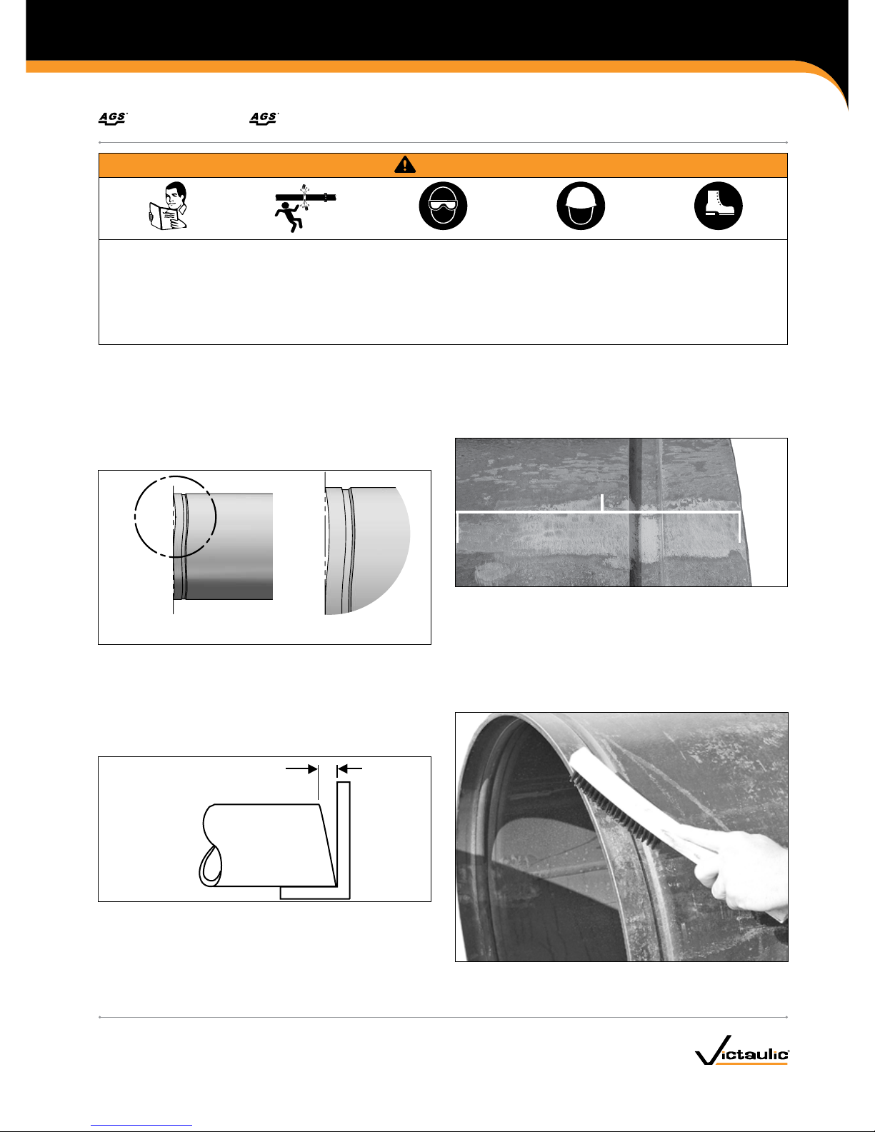
PIPE END VISUAL INSPECTION – ALL SIZES
1. Pipe ends shall be visually inspected in accordance with the
requirements listed below.
A
DETAIL A
2. The front edge of the pipe end shall be uniform with no concave/
convex surface features (refer to the drawing above). These
features will cause improper grooving roll tracking, resulting in
difficult coupling assembly.
3. If pipe cut-off is required, Victaulic recommends the use of
a mechanically-guided pipe cutting tool for proper pipe end
preparation. Free-hand pipe end cutting is not acceptable.
"S" Max.
4. Square cut the pipe ends (“S” dimension shown above) within
1/8 inch/3.2 mm.
PIPE PREPARATION – ALL SIZES
Photo Showing Pipe with Weld Seam
Ground 6 inches/152 mm Back from
Pipe End and an AGS Groove
1. Prior to grooving, the weld seams must be ground flush to the
pipe surface (inside diameter and outside diameter). Grind the
weld seam from the pipe end to a distance of 6 inches/152 mm
back from the pipe end. This area must be smooth and free from
indentations, projections, and roll marks to ensure a leak-tight seal.
1a. Groove the pipe in accordance with the Victaulic AGS grooving
specifications listed on the following page. NOTE: PIPE MUST BE
ROLL GROOVED WITH VICTAULIC AGS (RW) ROLL SETS.
1b. Clean the outside surface of the pipe, from the groove to the pipe
end, to remove all oil, grease, loose paint, and dirt
I-W 07/ W7 7_1
Couplings
STYLE W07 RIGID AND STYLE W77 FLEXIBLE
I-W07/W77INSTALLATION INSTRUCTIONS
www.victaulic.com
VICTAULIC IS A REGISTERED TRADEMARK OF VICTAULIC COMPANY. © 2009 VICTAULIC COMPANY. ALL RIGHTS RESERVED. PRINTED IN THE USA.
REV_E
Page 2
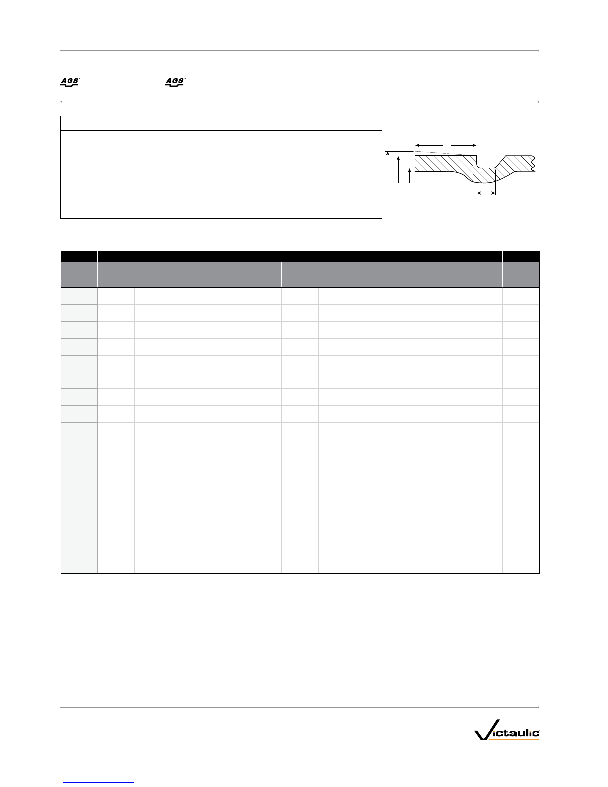
AGS Roll Grooving Specifications for Steel Pipe
Size Dimensions – inches/millimeter s lbs/kg
Nominal
Size
inches/
Actual mm
Outside Di ameter "OD " Gasket Seat "A" Groove Widt h "B"‡ Groove D iameter "C "
Maximum
Allowable
Flare
Diameter “ F”
Approx.
Weight Each
CouplingMaximum Minimum Basic Maximum Minimum Basic Maximum Minimum Max imum Minimum
14 14. 094 13. 969 1. 500 1.531 1. 437 0.455 0.460 0.450 13. 50 0 13.455 14.23 49.0
355.6 358. 0 35 4.8 3 8.1 38.9 36.5 11 .6 11. 7 11.4 3 42.9 341. 8 3 61.4 22.2
16 16. 094 15.9 69 1. 500 1. 531 1. 437 0.455 0.460 0.450 15. 50 0 15.4 55 16. 23 61.0
406.4 408.8 405.6 38 .1 38.9 36.5 11. 6 11.7 11. 4 393.7 392. 6 412.2 2 7.7
18 18. 094 17. 9 69 1.500 1.5 31 1.437 0.455 0.460 0.450 17. 5 0 0 1 7.4 55 18.2 3 7 1.0
45 7. 0 459. 6 456.4 38 .1 38.9 36.5 11. 6 11.7 11. 4 444.5 443. 4 463.0 32 .2
20 20.094 19.9 69 1. 500 1. 531 1.4 37 0.455 0.460 0 .450 19.50 0 19. 455 20.23 82.0
508.0 510. 4 50 7. 2 38 .1 3 8.9 36.5 11. 6 11. 7 11. 4 495 .3 49 4.2 5 13.8 3 7. 2
24 24 .094 23.969 1.50 0 1.531 1.4 37 0.455 0.460 0 .450 23.500 23.455 24. 23 116 . 0
610. 0 612 .0 608.8 38 .1 3 8.9 36.5 11. 6 11. 7 11. 4 59 6.9 59 5.8 615. 4 52. 6
26 26.094 25.969 1.75 0 1.781 1. 687 0. 535 0.540 0.530 25. 430 25.370 26.30 205.0
660.0 662. 8 6 59.6 44.5 45. 2 42. 8 13 .6 13 .7 13 .5 6 45.9 644.4 668.0 93.0
28 28.09 4 27.9 6 9 1. 750 1. 781 1.6 87 0. 535 0.540 0.53 0 27.4 30 27. 37 0 28. 30 220.0
711 . 0 713 .6 710 .4 44.5 45.2 42.8 13. 6 13.7 13. 5 696.7 695.2 7 18.8 10 0.0
30 30.094 29.969 1. 750 1.7 81 1.68 7 0. 535 0.540 0.530 29.43 0 29.370 30.30 2 27. 0
762. 0 764 .4 761. 2 44.5 45 .2 42. 8 13 .6 13 .7 13 .5 7 47. 5 746 .0 769 .6 103.0
32 32 .094 31. 969 1. 750 1. 781 1.6 87 0. 535 0.540 0.53 0 31. 430 31. 370 32.30 242.0
813. 0 8 15.2 812 .0 4 4.5 45 .2 42. 8 13 .6 13 .7 13 .5 79 8.3 796.8 820.4 11 0. 0
36 36.094 35.96 9 1. 750 1.7 81 1.68 7 0. 535 0.540 0.530 35.43 0 35.370 36.30 268.0
914. 0 916. 8 9 13. 6 4 4.5 45 .2 42. 8 13 .6 13 .7 13 .5 899.9 898.4 922 .0 12 2.0
40 40.094 39.969 2.000 2 .031 1. 937 0.562 0.567 0.55 7 3 9.375 39. 315 40.30 340.0
1016. 0 10 18.4 10 15.2 50.8 51.6 49. 2 14. 3 14.4 14 .1 1000.1 998.6 1023. 6 154. 0
42 42 .094 41. 969 2.000 2 .031 1. 937 0.562 0.567 0. 557 41.375 41.3 15 42.30 360.0
10 67. 0 10 69.2 106 6.0 50.8 51.6 49.2 14. 3 14.4 14 .1 1050.9 104 9.4 1074. 4 163 .0
46 46.094 45.969 2.000 2. 031 1.9 37 0.562 0 .567 0. 557 45.375 45 .315 46.30 415 .0
116 8 . 0 11 70 . 8 116 7. 6 50.8 51.6 49.2 14. 3 14.4 14 .1 11 52 . 5 1151 . 0 1176 . 0 18 8. 0
48 48.094 47. 96 9 2.000 2 .031 1. 937 0.562 0.567 0.55 7 47.375 47. 315 48.30 42 5.0
1219. 0 12 21.6 1218. 4 50.8 51.6 49. 2 14. 3 14.4 14 .1 120 3. 3 1201 .8 12 26. 8 193 .0
54
54.094 53.969 2.500 2 .531 2. 437 0.562 0. 567 0. 557 53.375 53. 315 54.30 648.0
1372 .0 1374.0 1370. 8 63.5 64.3 61.9 14. 3 14.4 14 .1 135 5.7 13 54 .2 137 9.2 294.0
56 56.094 55.9 69 2.500 2 .531 2 .437 0.562 0 .567 0. 557 55.375 55 .315 56.30 676. 0
1422 .0 1424. 8 14 21.6 63.5 64.3 61.9 14 .3 14.4 14.1 1406.5 140 5.0 14 30. 0 30 7.0
60 60.094 59.969 2.500 2. 531 2.4 37 0.562 0.5 67 0.557 59. 375 5 9.3 15 60.30 720.0
1524 .0 15 26. 4 15 23. 2 63.5 64.3 61.9 14. 3 14.4 14 .1 15 08. 1 1506.6 1531. 6 32 7. 0
‡ The Groove Width “B” dimension is listed for information only.
IMPORTANT – Grooving pipe to AGS specications enlarges the pipe length by approximately ⁄ inch (0.125 inch/3.2 mm) for each groove. For a pipe length with an AGS groove at each end, the
length will grow approximately ¼ inch (0.250 inch/6.4 mm) total. Therefore, the cut length should be adjusted to accommodate this growth.
EXAMPLE: If you need a 24-inch/610-mm length of pipe that will contain an AGS groove at each end, cut the pipe to a length of 23 ¾ inches/603 mm to allow for this growth.
NOTICE
When grooving pipe for use with Style W07 or Style W77 Couplings, Victaulic roll grooving •
tools must be equipped with Victaulic AGS (RW) roll sets. Style W07 and Style W77
Couplings MUST NOT be installed on pipe that is prepared with original-type grooving roll
sets.
The Groove Width “B” dimension will be achieved with properly maintained Victaulic tools •
equipped with Victaulic AGS (RW) roll sets.
It is critical to measure the Groove Diameter “C” dimension, along with the Gasket Seat “A” •
dimension and the Flare Diameter “F” dimension. These measurements must be within the
specifications listed in the table below for proper joint performance.
A
F
OD C
B
I-W 07/ W7 7_2
I-W07/W77
INSTALLATION INSTRUCTIONS
www.victaulic.com
VICTAULIC IS A REGISTERED TRADEMARK OF VICTAULIC COMPANY. © 2009 VICTAULIC COMPANY. ALL RIGHTS RESERVED. PRINTED IN THE USA.
REV_E
Couplings
STYLE W07 RIGID AND STYLE W77 FLEXIBLE
Page 3
INSTALLATION INSTRUCTIONS –
14 – 24-INCH/355.6 – 610.0-MM SIZES
THIS COUPLING ASSEMBLY HAS A TORQUE REQUIREMENT. REFER
TO THE INSTRUCTIONS IN THIS SECTION OR THE MARKINGS ON
THE HOUSINGS FOR THE SPECIFIC TORQUE REQUIREMENT.
1. Prepare the pipe by following the “Pipe Preparation – All Sizes”
section on page 2.
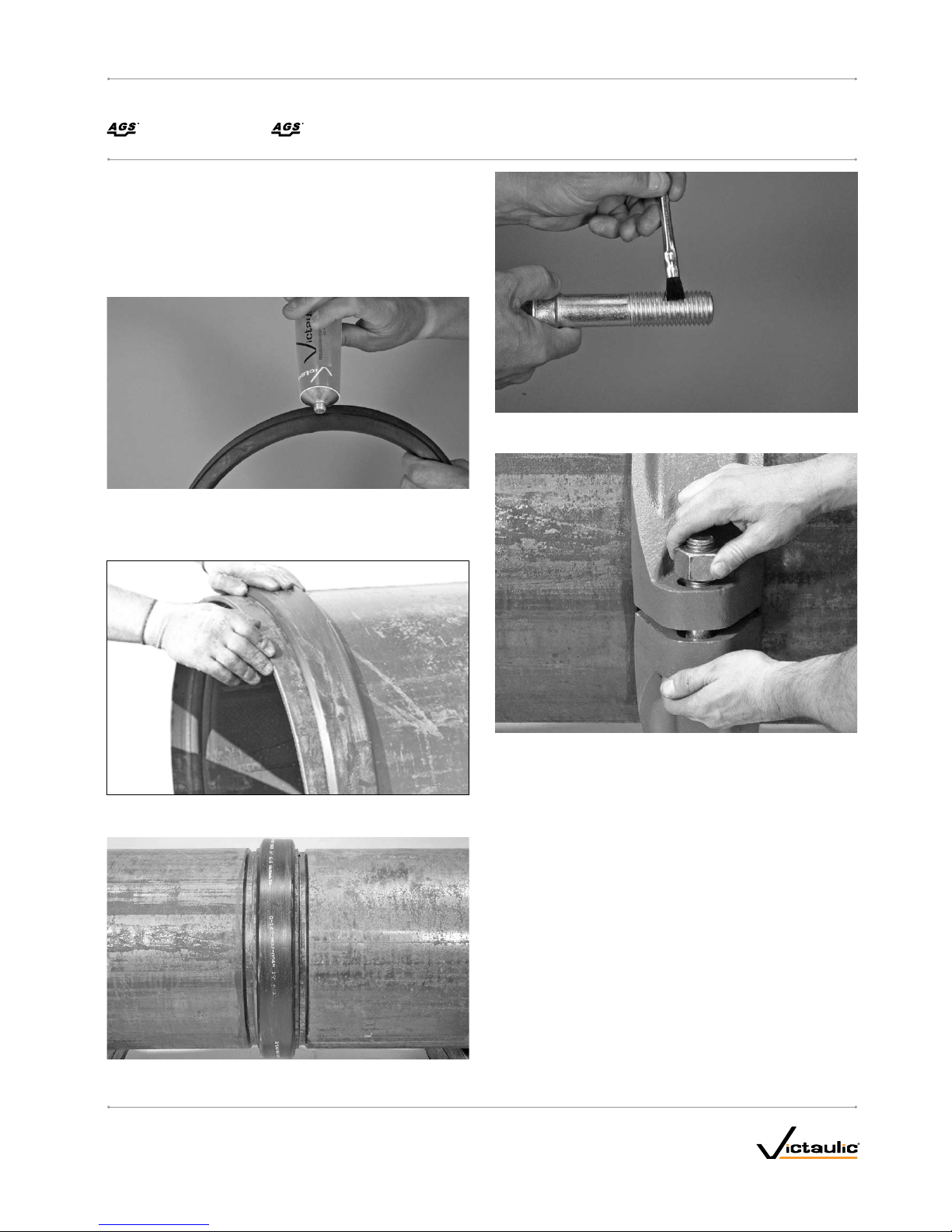
2. Check the gasket to make sure it is suitable for the intended
service. The color code identifies the gasket grade. Apply a thin
coat of Victaulic lubricant or silicone lubricant to the gasket lips
and exterior.
3. Position the gasket over the pipe end. Make sure the gasket does
not overhang the pipe end.
4. Align and bring the t wo pipe ends together. Slide the gasket into
position, and center it between the grooves in each pipe.
5. Apply a thin coat of Victaulic lubricant or silicone lubricant to the
bolt threads.
6. Install the housings over the gasket. Make sure the housings’
keys engage the grooves completely on both pipes. Support the
segments while preparing to install the bolts and nuts.
6a. Install the bolts, and thread the nuts finger-tight onto the bolts.
NOTE: Make sure the oval necks of the bolts seat properly in the
bolt holes.
I-W 07/ W7 7_3
I-W07/W77INSTALLATION INSTRUCTIONS
www.victaulic.com
VICTAULIC IS A REGISTERED TRADEMARK OF VICTAULIC COMPANY. © 2009 VICTAULIC COMPANY. ALL RIGHTS RESERVED. PRINTED IN THE USA.
REV_E
Couplings
STYLE W07 RIGID AND STYLE W77 FLEXIBLE
Page 4

7. Tighten the nuts evenly by alternating sides. Make sure the
housings’ keys engage the grooves completely. Continue to
tighten the nuts evenly until metal-to-metal bolt pad contact AND
the specified torque value are achieved. Refer to the “Required
Assembly Torques” table on this page. NOTE: Both conditions of
metal-to-metal bolt pad contact AND the specified torque value
are required for proper coupling assembly.
NOTE: It is important to tighten the nuts evenly by alternating sides
to prevent gasket pinching. Deep well sockets are recommended for
proper installation due to the longer bolt lengths associated with these
products. Deep well sockets provide the full nut engagement that is
necessary during tightening.
TO PREVENT LUBRICATION FROM DRYING OUT AND CAUSING
GASKET PINCHING, ALWAYS BRING THE BOLT PADS INTO METALTO-METAL CONTACT IMMEDIATELY AFTER ASSEMBLING THE
COUPLING ONTO THE PIPE.
Required Assembly Torques
Coupling Size Required Torques
Nominal Size
inches
Actual Out side Diameter
Inches/mm
ft-lbs
(N•m)
14 – 18
14.000 – 18.000 250
355.6 – 457.0 340
20 – 24
20.000 – 24.000 375
508.0 – 610.0 500
Style W07 and W77 Helpful Information
Size
Number of
Bolts/Nuts
Nut Size Socket Size
Nominal
Size
inches
Actual
Outside
Diameter
inches
mm inches/Metric inches/Metric
14 – 18
14.000 – 18.000
2
1 1 ⁄
355.6 – 457.0 M24 41
20 – 24
20.000 – 24.000
2
1 ⁄ 1 ⁄
508.0 – 610.0 M27 46
WARNING
Nuts must be tightened evenly until both conditions of metal-•
to-metal bolt pad contact AND the specified torque value are
achieved.
Always bring the bolt pads into metal-to-metal contact •
immediately after assembling the coupling onto the pipe.
Failure to follow these instructions could cause joint failure,
resulting in serious personal injury and/or property damage.
I-W 07/ W7 7_4
I-W07/W77
INSTALLATION INSTRUCTIONS
www.victaulic.com
VICTAULIC IS A REGISTERED TRADEMARK OF VICTAULIC COMPANY. © 2009 VICTAULIC COMPANY. ALL RIGHTS RESERVED. PRINTED IN THE USA.
REV_E
Couplings
STYLE W07 RIGID AND STYLE W77 FLEXIBLE
Page 5

INSTALLATION INSTRUCTIONS –
26 – 60-INCH/660.0 – 1524.0-MM SIZES
THIS COUPLING ASSEMBLY HAS A TORQUE REQUIREMENT. REFER
TO THE INSTRUCTIONS IN THIS SECTION OR THE MARKINGS ON
THE HOUSINGS FOR THE SPECIFIC TORQUE REQUIREMENT.
1. Prepare the pipe by following the “Pipe Preparation – All Sizes”
section on page 2.
2. Check the gasket to make sure it is suitable for the intended
service. The color code identifies the gasket grade. Apply a thin
coat of Victaulic lubricant or silicone lubricant to the gasket lips,
gasket exterior, and the interior surface of the coupling housings.
3. Position the gasket over the pipe end. Make sure the gasket does
not overhang the pipe end.
4. Align and bring the t wo pipe ends together.
I-W 07/ W7 7_5
I-W07/W77INSTALLATION INSTRUCTIONS
www.victaulic.com
VICTAULIC IS A REGISTERED TRADEMARK OF VICTAULIC COMPANY. © 2009 VICTAULIC COMPANY. ALL RIGHTS RESERVED. PRINTED IN THE USA.
REV_E
Couplings
STYLE W07 RIGID AND STYLE W77 FLEXIBLE
Page 6

4a. Slide the gasket into position, and center it between the grooves in
each pipe.
5. Apply a thin coat of Victaulic lubricant or silicone lubricant to the
bolt threads.
NOTICE
Lifting lugs are provided on 26 – 60-inch/660.0 – 1524.0-mm •
coupling housings to aid in assembly.
Due to the weight of 26 – 60-inch/660.0 – 1524.0-mm •
coupling housings, mechanical lifting equipment is strongly
recommended for safe and proper installation.
6. Using a strapping method, similar to the one shown in the
photos above, install the housings over the gasket. Make sure the
housings’ keys engage the grooves completely on both pipes.
I-W07/W77_6
I-W07/W77
INSTALLATION INSTRUCTIONS
www.victaulic.com
VICTAULIC IS A REGISTERED TRADEMARK OF VICTAULIC COMPANY. © 2009 VICTAULIC COMPANY. ALL RIGHTS RESERVED. PRINTED IN THE USA.
REV_E
Couplings
STYLE W07 RIGID AND STYLE W77 FLEXIBLE
Page 7

6a. Install a flat washer (supplied with the coupling) onto the end of
each bolt, and thread a nut finger-tight onto each bolt. NOTE: Make
sure the oval necks of the bolts seat properly in the bolt holes.
7. Tighten the nuts evenly by alternating sides (refer to the graphics in
the left column of this page for the tightening sequence). Make sure
the housings’ keys engage the grooves completely. Continue to tighten
the nuts evenly until metal-to-metal bolt pad contact AND the specified
torque value are achieved. Refer to the “Required Assembly Torques”
table on the following page. NOTE: Both conditions of metal-to-metal
bolt pad contact AND the specified torque value are required for
proper coupling assembly.
NOTE: It is important to tighten the nuts evenly to prevent gasket
pinching. Deep well sockets are recommended for proper installation
due to the longer bolt lengths associated with these products. Deep
well sockets provide the full nut engagement that is necessary during
tightening.
TO PREVENT LUBRICATION FROM DRYING OUT AND CAUSING
GASKET PINCHING, ALWAYS BRING THE BOLT PADS INTO METALTO-METAL CONTACT IMMEDIATELY AFTER ASSEMBLING THE
COUPLING ONTO THE PIPE.
I-W 07/ W7 7_7
I-W07/W77INSTALLATION INSTRUCTIONS
www.victaulic.com
VICTAULIC IS A REGISTERED TRADEMARK OF VICTAULIC COMPANY. © 2009 VICTAULIC COMPANY. ALL RIGHTS RESERVED. PRINTED IN THE USA.
REV_E
Couplings
STYLE W07 RIGID AND STYLE W77 FLEXIBLE
Page 8

GOOD
BAD
8. Visually inspect the bolt pads at each joint to ensure metal-tometal contact is achieved across the entire bolt pad section.
WARNING
Nuts must be tightened evenly until both conditions of metal-•
to-metal bolt pad contact AND the specified torque value are
achieved.
Always bring the bolt pads into metal-to-metal contact •
immediately after assembling the coupling onto the pipe.
Failure to follow these instructions could cause joint failure,
resulting in serious personal injury and/or property damage.
Required Assembly Torques
Coupling Size Required Torques
Nominal Size
inches
Actual Out side Diameter
Inches/mm
ft-lbs
(N•m)
26 – 28
26.000 – 28.000 375
660.0 – 711.0 500
30 – 36
30.000 – 36.000 500
762.0 – 914.0 678
40 – 60
40.000 – 60.000 600
1016.0 – 1524.0 814
Style W07 and W77 Helpful Information
Size
Number of
Bolts/Nuts /
Washers
Bolt/Nut /Washer
Size Socket Size
Nominal
Size
inches
Actual
Outside
Diameter
inches
mm inches/Metric inches/Metric
26 – 28
26.000 – 28.000
4
1 ⁄ 1 ⁄
660.0 – 711.0 M27 46
30 – 36
30.000 – 36.000
4
1 ¼ 2
762.0 – 914.0 M30 50
40 – 60
40.000 – 60.000
4
1 ½ 2 ⁄
1016.0 – 1524.0 M36 60
I-W07/W77INSTALLATION INSTRUCTIONS
Couplings
STYLE W07 RIGID AND STYLE W77 FLEXIBLE
I-W07/ W77
For complete contact information, visit w ww.victaulic.com
I-W07/W77 3993 REV E UPDATED 06/2009 Z000W07W77
VICTAULIC IS A REGISTERED TRADEMARK OF VICTAULIC COMPANY. © 2009 VICTAULIC COMPANY. ALL RIGHTS RESERVED. PRINTED IN THE USA.
 Loading...