

Victaulic FireLock NXT 764 Series, FireLock NXT 768 Series, FireLock NXT 769 Series Replacement Instructions Manual
Page 1
Water Supply Main
Control Valve
Series 764, 768 and 769
REPLACING THE DIAPHRAGM IN SERIES 764, 768, AND 769 FIRELOCK NXT™ FIRE PROTECTION VALVES
IMPORTANT INFORMATION
WARNING WARNING
I-NXT.DIAREPLACEMENT KIT INSTRUCTIONS
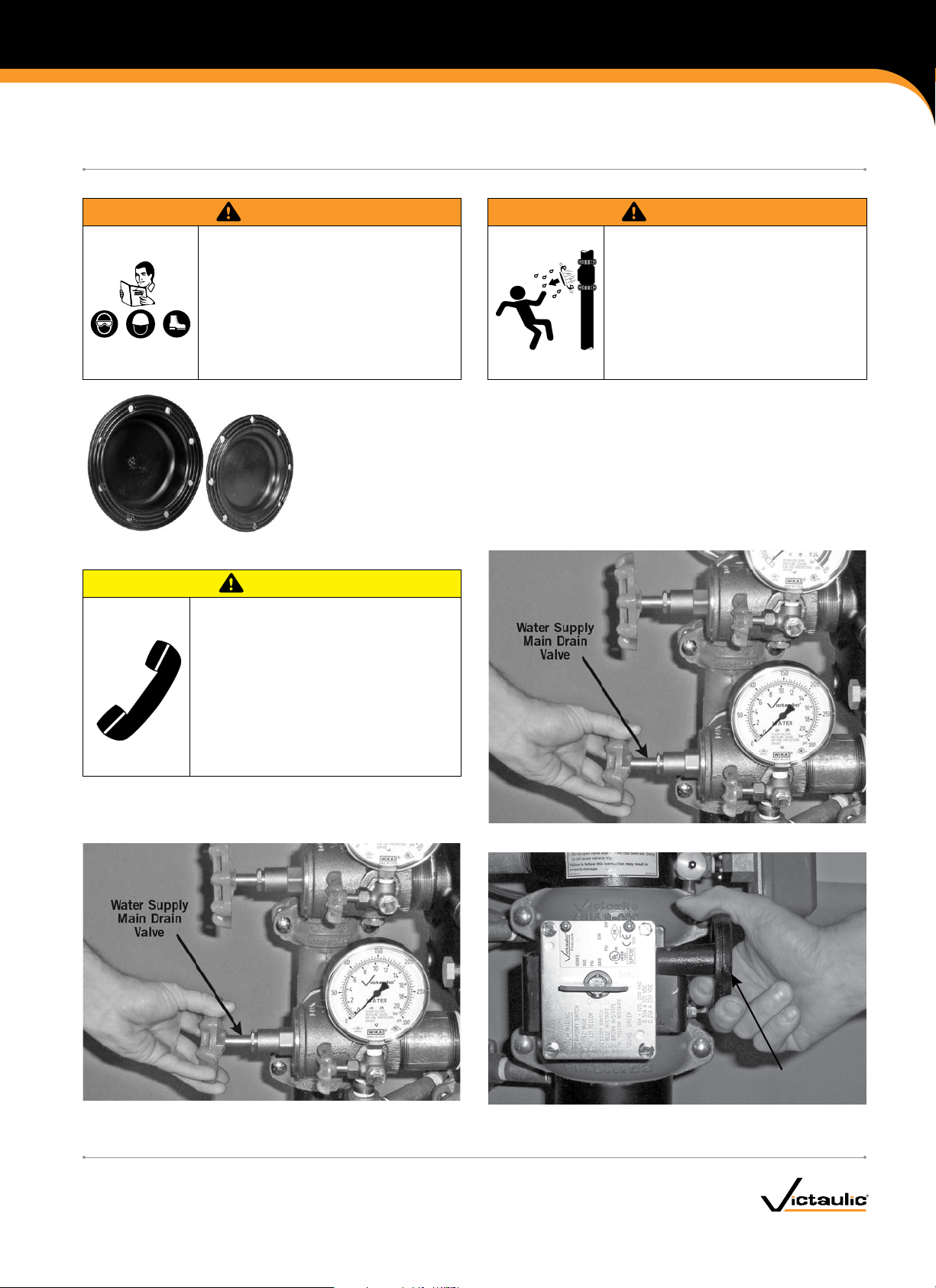
Read and understand all instructions •
before attempting to perform maintenance
on any Victaulic piping products.
Wear safety glasses, hardhat, and foot •
protection.
Failure to follow these instructions could
result in serious personal injury, property
damage, and/or product failure.
The following instructions are a guide for removing and replacing the diaphragm in Series 764, 768,
and 769 FireLock NXT™ Fire Protection Valves. It is important to replace the diaphragm with a new,
Victaulic-supplied diaphragm of the correct diameter to ensure proper valve operation.
REMOVING THE SYSTEM FROM SERVICE
CAUTION
Any activities that require taking the •
valve out of service may eliminate the fire
protection provided.
Before servicing or testing the system, •
notify the authority having jurisdiction.
Consideration of a fire patrol should be •
given in the affected areas.
Failure to follow these instructions could
result in serious personal injury and/or
property damage.
Depressurize and drain the piping •
system before attempting to remove,
adjust, or perform maintenance on any
Victaulic piping products.
Failure to follow this instruction could
result in serious personal injury and/or
property damage.
1. Notify the authority having jurisdiction, remote station alarm monitors, and those in the affected area that the system is being taken
out of service.
2. Open the water supply main drain valve fully to flush the water
supply of any contaminants.
www.victaulic.com
VICTAULIC IS A REGISTERED TRADEMARK OF VICTAULIC COMPANY. © 2009 VICTAULIC COMPANY. ALL RIGHTS RESERVED. PRINTED IN THE USA.
REV_ A
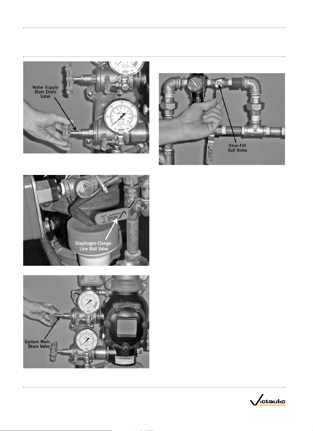
3. Close the water supply main drain valve.
4. Close the water supply main control valve to take the system out of
service.
I-NXT.DIA_1
Page 2
REPLACEMENT KIT INSTRUCTIONS
Series 764, 768 and 769
REPLACING THE DIAPHRAGM IN SERIES 764, 768, AND 769 FIRELOCK NXT™ FIRE PROTECTION VALVES
NOTE: If the system has operated, open the remote system test valve
(inspector’s test connection) and any auxiliary drain valves.
5. Open the water supply main drain valve.
6. Confirm that water is not flowing from the water supply main drain
valve.
9. Close the slow-fill ball valve on the Air Maintenance Trim Assembly
(AMTA).
10. PUSH DOWN ON THE AUTO DRAIN SCREW TO REMOVE
PRESSURE IN THE DIAPHRAGM CHARGE LINE.
I-NXT.DIA
7. Close the diaphragm-charge-line ball valve.
8. Open the system main drain valve to drain any water that has
accumulated and to release system air pressure.
www.victaulic.com
VICTAULIC IS A REGISTERED TRADEMARK OF VICTAULIC COMPANY. © 2009 VICTAULIC COMPANY. ALL RIGHTS RESERVED. PRINTED IN THE USA.
I-NXT.DIA_2
REV_ A
Page 3
Series 764, 768 and 769
REPLACING THE DIAPHRAGM IN SERIES 764, 768, AND 769 FIRELOCK NXT™ FIRE PROTECTION VALVES
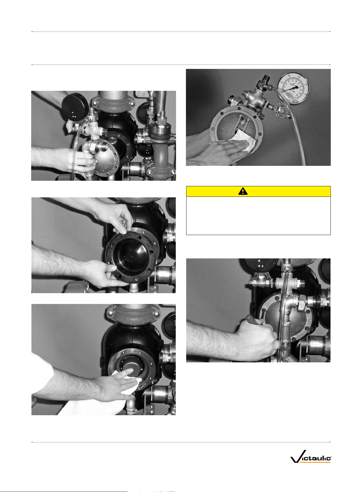
REMOVING AND REPLACING THE DIAPHRAGM ASSEMBLY
1. Break the unions that connect the trim to the diaphragm cover.
Refer to the applicable trim drawing for details.
4a. Clean the inside of the diaphragm cover to remove any foreign
material.
2. Remove the cap screws from the diaphragm cover, and pull the
diaphragm cover/trim off the valve.
CAUTION
I-NXT.DIAREPLACEMENT KIT INSTRUCTIONS
3. Remove the diaphragm from the valve body.
4. Clean the back of the valve body to remove any debris that may
interfere with proper diaphragm seating.
Use caution when installing a new diaphragm into the valve •
body.
Failure to follow this instruction could cause damage to the
diaphragm, resulting in improper valve operation and valve
leakage.
5. Replace the diaphragm with a new, Victaulic-supplied diaphragm.
Align the holes in the diaphragm with the holes in the valve body.
Be careful not to damage the diaphragm during installation.
6. Align the holes of the diaphragm cover with the holes in the diaphragm/valve body. Tighten all cap screws into the diaphragm
cover/valve body.
7. Re-attach the trim at the unions that were loosened in step 1.
Refer to the applicable trim drawing for details. MAKE SURE
ALL UNIONS THAT WERE LOOSENED TO PERMIT ACCESS
TO THE DIAPHRAGM COVER ARE RE-TIGHTENED BEFORE
ATTEMPTING TO PLACE THE SYSTEM BACK IN SERVICE.
8. Place the system back in service by following the “Placing the
System in Service” section in the applicable installation, maintenance, and testing manual for the valve configuration.
www.victaulic.com
VICTAULIC IS A REGISTERED TRADEMARK OF VICTAULIC COMPANY. © 2009 VICTAULIC COMPANY. ALL RIGHTS RESERVED. PRINTED IN THE USA.
REV_ A
I-NXT.DIA_3
Page 4

Series 764, 768 and 769
REPLACING THE DIAPHRAGM IN SERIES 764, 768, AND 769 FIRELOCK NXT™ FIRE PROTECTION VALVES
I-NXT.DIAREPLACEMENT KIT INSTRUCTIONS
For complete contact information, visit www.victaulic.com
I-NXT.DIA 5658 REV A UPDATED 05/2009 Z000NXTDIA
VICTAULIC IS A REGISTERED TRADEMARK OF VICTAULIC COMPANY. © 2009 VICTAULIC COMPANY. ALL RIGHTS RESERVED. PRINTED IN THE USA.
I-NXT.DIA
 Loading...