

Page 1

I-800
Victaulic FireLock® CPVC
Sprinkler System Products
DESIGN AND
INSTALLATION MANUAL
I-800
DESIGN AND INSTALLATION MANUAL
If you need additional copies of any instructions, or if you have
questions about the safe and proper installation of Victaulic products,
contact Victaulic.
For the most up-to-date information on Victaulic products, visit:
www.victaulic.com
Page 2

Page 3

I-800_1
FIRELOCK CPVC SPRINKLER
SYSTEM PRODUCTS REV_J
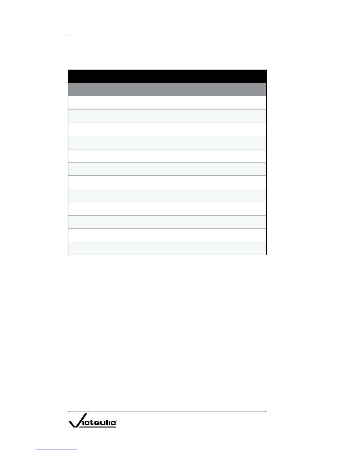
QUICK REFERENCE
Frequently Referenced Sections Page(s)
Handling and Storage of CPVC Pipe and Fittings ............... 7
Chemical Compatibility with CPVC Pipe and Fittings ............. 8
Use with Other Manufacturers’ Pipes, Fittings,
and Solvent Cements:................................. 20
Set and Cure Times ................................ 26 – 27
Painting Pipe and Fittings ............................... 35
Hanger/Support Spacing ............................ 44 – 46
Page 4

I-800_2
FIRELOCK CPVC SPRINKLER
SYSTEM PRODUCTS REV_J
TABLE OF CONTENTS
Purpose of This Manual .................................................3
Hazard Identification ...................................................3
Installer Safety Instructions ..............................................4
Introduction ..........................................................5
Helpful Information – English and Metric Conversion Chart .....................6
Handling and Storage of CPVC Pipe and Fittings..............................7
Chemical Compatibility with CPVC Pipe and Fittings...........................8
Handling and Storage of One-Step Solvent Cement............................9
System Approvals, Listings, Usage, and Standards ...........................10
Light Hazard Occupancies:............................................10
Residential Occupancies: .............................................10
Concealed Installations: ..............................................10
Ordinary Hazard Installations: ..........................................11
Exposed Installations: ................................................11
Extended Coverage Sprinklers: . . . . . . . . . . . . . . . . . . . . . . . . . . . . . . . . . . . . . . . . . 11
Return Air Plenums Installations: .......................................12
Combustible Attic Installations with Specific-Application Sprinklers: .............12
Multi-Purpose Systems: ..............................................12
Combustible Concealed Installations with Specific-Application Sprinklers: ........13
Unfinished Basements with Exposed, Solid-Wood Joist Installations: ............13
System Risers (Protected and Exposed):..................................15
Garage Installations: .................................................17
High Temperature Areas: .............................................17
Cold Temperature Areas: .............................................18
Underground Fire Service: ............................................19
Factory Mutual:.....................................................19
NSF
®
International: ..................................................19
Penetrating Fire-Rated Walls and Partitions: ...............................20
Heat Sources and Open Ceiling Areas: ...................................20
Use with Other Manufacturers’ Pipes, Fittings, and Solvent Cements: ...........20
Installation & Joining Section............................................21
Cutting the Pipe ....................................................21
Deburring and Beveling...............................................22
Fitting Preparation ..................................................22
Solvent Cement Application ...........................................23
Assembly .........................................................26
Set and Cure Times .................................................26
Threaded Connections ...............................................28
Transition to Other Materials ...........................................30
Flange Connections .................................................30
Grooved Connections ................................................32
System Acceptance Testing (Hydrostatic Pressure Test) .......................34
Painting Pipe and Fittings ..............................................35
Cut-In Procedures for System Modification or Repair .........................36
Accessories..........................................................38
Adjustable Sprinkler Adapter Installation Instructions .........................42
Engineering Data Section ...............................................43
Pipe and Fitting Specifications .........................................43
Hydraulic Design....................................................43
Hanger/Support Spacing................................................44
Riser Supports .......................................................47
Exposed Installations ................................................47
Earthquake Bracing .................................................47
Tre nc hing ...........................................................48
Snaking/Deflection of Pipe..............................................49
Backfilling...........................................................51
Appendix A – Design Criteria for Combustible Concealed Installations
Incorporating Victaulic FireLock CPVC Sprinkler System Products and Victaulic
Model V2502 or Viking Coin™ (VK900) Specific Application Sprinklers ........52
Appendix B – Design Criteria for Combustible Concealed Installations
Involving Victaulic FireLock CPVC Sprinkler System Products and
Tyco Fire Products Model CC1 Combustible Concealed Sprinklers .............57
Material Properties ....................................................58
Expansion and Contraction..............................................59
Style #899 FireLock CPVC One-Step Solvent Cement MSDS Sheet ..............62
Warranty ............................................................64
Facilities ...........................................................B/C
Page 5
I-800_3
FIRELOCK CPVC SPRINKLER
SYSTEM PRODUCTS REV_J
PURPOSE OF THIS MANUAL
This manual is intended for use by specifiers, installers, and users in the selection,
design, installation, and inspection of Victaulic FireLock CPVC Piping Systems for Fire
Protection Service. Due to the critical safety and loss prevention uses of such systems,
all information contained herein is considered vital to obtain proper system performance
and must be read and understood carefully before starting the installation. If you have
any questions, or if you need additional copies of this manual, contact Victaulic at
(800) PICK VIC or (800) 742-5842.
HAZARD IDENTIFICATION
Definitions for identifying the various hazard levels are provided below.
This safety alert symbol indicates important safety messages. When you
see this symbol, be alert to the possibility of personal injury. Carefully read
and fully understand the message that follows.
DANGER
The use of the word “DANGER” •
identifies an immediate hazard
with a likelihood of death or serious
personal injury if instructions,
including recommended
precautions, are not followed.
WARNING
The use of the word “WARNING” •
identifies the presence of hazards
or unsafe practices that could
result in death or serious personal
injury if instructions, including
recommended precautions, are not
followed.
CAUTION
The use of the word “CAUTION” •
identifies possible hazards or
unsafe practices that could result
in personal injury and product or
property damage if instructions,
including recommended
precautions, are not followed.
NOTICE
The use of the word “NOTICE” •
identifies special instructions that
are important but not related to
hazards.
Page 6

I-800_4
FIRELOCK CPVC SPRINKLER
SYSTEM PRODUCTS REV_J
INSTALLER SAFETY INSTRUCTIONS
Read and understand this manual before proceeding with the installation 1.
and testing of the Victaulic FireLock CPVC System. Education and a complete
understanding of the instructions provided are requirements for the installer of the
Victaulic FireLock CPVC System. These instructions contain important information. If you
need additional copies, or if you have any questions about the safe installation and use
of this system, contact Victaulic Company, P.O. Box 31, Easton, PA 1804 4-0 031 USA,
Telephone 800-PICK-VIC or 800-742-58 42.
Use only recommended accessories.
2. Use of improper accessories or unapproved
system components in conjunction with the Victaulic FireLock CPVC System will void the
warranty and may result in improper operation of the system.
Avoid dangerous environments.
3. If utilizing electrically powered tools for installation,
be sure that the area is free of moisture or wetness that could create an unsafe condition.
Keep work area well illuminated. Allow sufficient space for measuring and system dry fit
to accommodate proper installation.
Prevent back injury.
4. Always practice safe lifting and installation techniques.
Use only tools specifically designed for plastic pipe and fittings.
5.
Inspect the products.6. Be sure that all parts are included and that you have all
necessary tools available to properly install the system.
Wear safety glasses, hardhat, and safety footwear.
7. Always practice safety first.
When solvent-cementing, always work in a well-ventilated area.
8.
Wear protective gloves.9. PVA-coated protective gloves are recommended for use
while solvent cementing. If hands come in contact with solvent cement, use a waterless,
abrasive soap.
When solvent-cementing, avoid sources of heat or open flames. DO NOT smoke.
10.
Keep work area clean.11. Cluttered areas and slippery floors invite accidents.
Wear ear protection.
12. Protect your hearing if you are exposed to long periods of very
noisy job-site operations.
Keep visitors away.
13. All visitors should be kept a safe distance away from the work
area.
Page 7
I-800_5
FIRELOCK CPVC SPRINKLER
SYSTEM PRODUCTS REV_J
INTRODUCTION
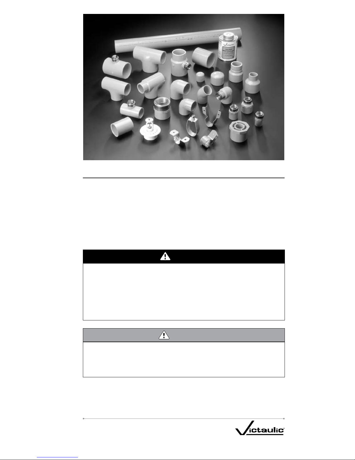
Victaulic FireLock CPVC Sprinkler System Products are manufactured from high-quality,
Post-Chlorinated Polyvinyl Chloride (CPVC), a specialty thermoplastic material. Victaulic
FireLock CPVC Sprinkler System Products are designed specifically for fire sprinkler
systems. They provide unique advantages over traditional sprinkler piping systems
through superior hydraulics, ease of installation and handling, and quick assembly using
readily available, inexpensive tools. In addition, Victaulic Style #899 FireLock CPVC
One-Step Solvent Cement eliminates the need for primers that are typical in two-step
cementing processes. The one-step process simplifies installation and reduces labor
time.
DANGER
Victaulic FireLock CPVC Sprinkler System Products must be used in wet systems •
only. A wet piping system contains water and is connected to a water supply
system so that the water will discharge immediately when the sprinkler activates.
Victaulic FireLock CPVC Sprinkler System Products must never be used in a •
system that uses compressed air or other gases.
Failure to follow these instructions could result in severe personal injury, significant
property damage, and product damage.
CAUTION
DO NOT use Victaulic FireLock CPVC Sprinkler System Products in outdoor •
applications. These products are not Listed for outdoor applications.
Failure to follow this instruction could result in product failure and property
damage and will not be covered under the Victaulic CPVC warranty.
Page 8
I-800_6
FIRELOCK CPVC SPRINKLER
SYSTEM PRODUCTS REV_J
HELPFUL INFORMATION – ENGLISH AND METRIC
CONVERSION CHART
The following chart is a guideline for converting English and metric measurements.
The English measurements, given throughout this manual, are the actual values. It is
important that accurate metric conversions are made to ensure proper installation of
Victaulic FireLock CPVC Sprinkler System Products.
Convert Imperial (U.S.) to Metric
Convert Metric to Imperial (U.S.)
25.4 ×
Inches
(In.)
⇔
Millimeters
(mm)
× 0.03937
0.3048 ×
Feet
(Ft.)
⇔
Meters
(m)
× 3.281
0.4536 ×
Pounds
(Lbs.)
⇔
Kilograms
(kg)
× 2.205
28.35 ×
Ounces
(Oz.)
⇔
Grams
(g)
× 0.03527
6.894 ×
Pressure
(psi)
⇔
Kilopascals
(kPa)
× 0.145
.069 × Pressure
⇔
Bar × 14.5
4.45 ×
End Load
(Lbs.)
⇔
Newtons
(N)
× 0.2248
1.356 ×
Torque
(Lb. Ft.)
⇔
Newton Meters
(N•m)
× 0.738
F – 32 ÷ 1.8
Temp.
(°F)
⇔
Celsius
(°C)
C + 17.78 × 1.8
745.7 ×
Horsepower
(hp)
⇔
Watts
(w)
× 1.341 × 10
-3
3.785 ×
Gal. per Min.
(GPM)
⇔
Liters per min.
(L/M)
× 0.2642
3.7865 ×
10
-3
Gal. per Min.
(GPM)
⇔
Cubic Meters per min.
(m3/m)
× 264.2
Page 9
I-800_7
FIRELOCK CPVC SPRINKLER
SYSTEM PRODUCTS REV_J
HANDLING AND STORAGE OF
CPVC PIPE AND FITTINGS
Victaulic FireLock CPVC Sprinkler System pipe and fittings should be stored at normal
ambient temperatures, which must not exceed the maximum installation temperature of
1 50 °F.
Victaulic recommends storing FireLock CPVC Sprinkler System Products indoors where
the product will not be exposed to heat-producing sources or sunlight. For extended
indoor storage, the area must be well ventilated so that the ambient temperature does not
exceed 150ºF.
If stored outdoors, Victaulic FireLock CPVC Sprinkler System Products must be covered
with a non-transparent material to reduce the risk of extended exposure to sunlight and
heat absorption, which could cause discoloration and weakening of CPVC material.
Victaulic FireLock CPVC Sprinkler System Fittings must be stored in their original
containers to prevent dirt accumulation and to help reduce the possibility of damage.
Excessive loading (i.e. stacking, point loading, etc.) or excessive strapping or banding
must be avoided to prevent CPVC material from warping. DO NOT drop CPVC products or
allow anything to drop on them.
Before installation, CPVC products must be inspected for any scratches, splits, gouges,
or warping that may have occurred from improper handling or storage. Damaged sections
of CPVC pipe must be cut out and discarded. Any damaged fittings must be discarded.
WARNING
Victaulic FireLock CPVC Sprinkler System pipe and fittings MUST NOT be •
subjected to prolonged sunlight exposure.
The ambient storage temperature MUST NOT exceed 150ºF.•
If stored outdoors, fittings must be stored in the original shipping containers, •
and pipe must be covered with a non-transparent material.
DO NOT install Victaulic FireLock CPVC Sprinkler System pipe and fittings that •
have been damaged during handling or storage.
Failure to follow these instructions could cause system failure, resulting in property
damage and personal injury due to leaks.
Page 10
I-800_8
FIRELOCK CPVC SPRINKLER
SYSTEM PRODUCTS REV_J
CHEMICAL COMPATIBILITY WITH
CPVC PIPE AND FITTINGS
When combining steel with Victaulic FireLock CPVC products in a system, all steel
components must be degreased then flushed thoroughly to remove internal and external
oils before assembly.
FireLock CPVC products may be damaged by chemicals that are not corrosive to metallic
piping. These damaging chemicals can be found in common substances used in
construction and residential settings. Specific chemicals or chemical vapors that contact
CPVC can weaken or severely damage the material.
DO NOT expose product to edible oils, cooking oils, esters, ketones, or glycol-based antifreeze fluids.
DO NOT expose product to petroleum-based substances, such as cutting oils, packing
oils, traditional pipe thread paste and dope, termiticides, insecticides, surfactants,
plasticizers, and building caulks.
To avoid contamination with hydrocarbons, DO NOT store CPVC fittings in bins with metal
fittings or handle CPVC products with oil-contaminated hands or gloves.
Refer to the following:
“Threaded Connections” section for compatible thread sealants
“Grooved Connections” section for compatible lubricants
“Penetrating Fire-Rated Walls and Partitions” section for compatible fire-stopping
products
WARNING
CPVC piping components, including Victaulic FireLock CPVC Sprinkler System •
Products, may be damaged by chemicals that are not corrosive to metallic
piping. These damaging chemicals can be found in common substances used in
construction and residential settings.
DO NOT expose CPVC products to edible oils, cooking oils, esters, ketones, or •
glycol-based anti-freeze fluids.
DO NOT expose CPVC products to petroleum-based substances, such as •
cutting oils, packing oils, traditional pipe thread paste and dope, termiticides,
insecticides, surfactants, plasticizers, and building caulks.
When combining steel with CPVC products in a system, all steel components •
must be degreased then flushed thoroughly to remove internal and external oils
before assembly.
To avoid contamination with hydrocarbons, do not store CPVC products in •
containers with metal fittings.
Handle CPVC products with clean hands and gloves only.•
Failure to follow these instructions may cause cracks or fractures in CPVC
products, resulting in property damage and personal injury due to leaks or flooding.
Alternatively, partial or full system replacement may be required due to the
presence of visible cracks.
For questions regarding chemical compatibility with CPVC products, contact Victaulic at
1-800-554-4434 or by e-mail at engserv@victaulic.com.
Page 11
I-800_9
FIRELOCK CPVC SPRINKLER
SYSTEM PRODUCTS REV_J
HANDLING AND STORAGE OF
ONE-STEP SOLVENT CEMENT
Victaulic Style #899 FireLock CPVC One-Step Solvent Cement must be stored out of
direct sunlight in ambient temperatures between 40°F and 110°F. The solvent cement
may be used for a period of two years from the date stamped on the container. Expired
solvent cement must be discarded in an environmentally friendly fashion, in accordance
with local regulations. To prolong the life of the cement, the containers must be kept
tightly closed when not in use and covered as much as possible during use. Refer to the
“Solvent Cementing Procedures” section for more information.
DANGER
Before using Victaulic Style #899 FireLock CPVC One-Step Solvent Cement, •
refer to ASTM-F402-05, “Standard Practice for Safe Handling of Solvent
Cements, Primers, and Cleaners Used for Joining Thermoplastic Pipe and
Fittings.” In addition, refer to the solvent cement Material Safety Data Sheet
(MSDS) and the solvent cement can label for important information.
Victaulic Style #899 FireLock One-Step Solvent Cement is highly flammable. •
Make sure all ignition sources are eliminated before use.
Avoid breathing solvent cement vapors, and use solvent cement only in well-•
ventilated areas. Explosion-proof, general mechanical ventilation or local exhaust
is recommended to maintain vapor concentrations below recommended exposure
limits. In confined or partially enclosed areas, a NIOSH-approved, organic-vapor
cartridge respirator with a full-face piece is recommended.
Avoid frequent contact with skin. PVA coated gloves and an impervious apron •
are recommended.
Avoid contact with eyes. Splash-proof chemical goggles are recommended.•
Failure to follow these instructions could result in serious personal injury.
WARNING
Follow all instructions contained in this manual when solvent cementing •
Victaulic FireLock CPVC Sprinkler System products.
Avoid puddling solvent cement on or within the fitting or pipe.•
DO NOT allow solvent cement to run into the inside or on the outside of the pipe •
or fitting.
Failure to follow these instructions could cause the pipe or fitting to fracture,
resulting in serious personal injury and/or significant property damage.
Page 12
I- 80 0_10
FIRELOCK CPVC SPRINKLER
SYSTEM PRODUCTS REV_J
SYSTEM APPROVALS, LISTINGS,
USAGE, AND STANDARDS
Victaulic FireLock CPVC Sprinkler System Products are Underwriters Laboratories Inc.
(UL) Listed and Factory Mutual (FM) Approved for use in wet-pipe sprinkler systems.
In addition, these products are approved by NSF
®
International for use in potable water
systems (refer to page 19 for more information). Victaulic Style #899 FireLock CPVC
One-Step Solvent Cement meets ASTM-F493 and NSF International requirements.
National Fire Protection Association (NFPA) Standards 13, 13R, and 13D must be
referenced for design and installation requirements in addition to this manual.
The following section summarizes the agency approvals, listings, usage, and standards
that Victaulic FireLock CPVC Sprinkler System Products meet. For more specific listing
information concerning FM or NSF International, contact Victaulic.
Light Hazard Occupancies:
Victaulic FireLock CPVC Sprinkler System Products are UL Listed for use in Light
Hazard Occupancies, as defined in NFPA 13, “Standard for the Installation of Sprinkler
Systems.”
Residential Occupancies:
Victaulic FireLock CPVC Sprinkler System Products are UL Listed for use in:
Residential occupancies, as defined in NFPA 13R, “Standard for the Installation
1.
of Sprinkler Systems in Residential Occupancies up to and Including Four Stories in
Height.”
Residential occupancies, as defined in NFPA 13D, “Standard for the Installation of
2.
Sprinkler Systems in One- and Two-Family Dwellings and Manufactured Homes.”
Residential occupancies, as defined in NFPA 13, “Automatic Sprinkler Systems
3.
Handbook 2007 Edition”
Concealed Installations:
Victaulic FireLock CPVC Sprinkler System Products are UL Listed for use in concealed
installations with the following provisions.
The minimum protection shall consist of one layer of •
⁄-inch gypsum wallboard,
½-inch plywood soffits, or a suspended membrane ceiling with lay-in panels or
tiles having a weight of not less than .35 lbs/ft
2
when installed with metallic support
grids.
The minimum protection for residential occupancies, defined in NFPA 13D and 13R, •
may consist of one layer of
½-inch plywood.
Victaulic FireLock CPVC Sprinkler System Products must be used in sprinkler •
systems employing sprinklers rated at 225°F or lower.
NOTICE
Victaulic FireLock CPVC Sprinkler System Products CANNOT be installed in •
spaces defined by NFPA 13 as combustible, concealed spaces that require
sprinklers, unless the space is protected by sprinklers that are specifically Listed
for the application.
NFPA 13D and NFPA 13R permit the omission of sprinklers in combustible, •
concealed spaces. Victaulic FireLock CPVC Sprinkler System Products can be
installed in these areas when sprinkling residential occupancies in accordance
with these standards.
Page 13

I-8 00_11
FIRELOCK CPVC SPRINKLER
SYSTEM PRODUCTS REV_J
Ordinary Hazard Installations:
In accordance with NFPA 13 (2007 Edition), paragraph 6.3.6.2, “Pipe or tube listed •
for light hazard occupancies shall be permitted to be installed in ordinary hazard
rooms of otherwise light hazard occupancies where the room does not exceed
400 ft
2
.” Follow all instructions contained in this manual for proper installation of
Victaulic FireLock CPVC pipe and fittings.
Exposed Installations:
Victaulic FireLock CPVC Sprinkler System Products are UL Listed for use in installations
without protection (exposed), with the following restrictions:
Exposed CPVC Fire Sprinkler piping is installed below a smooth, flat, horizontal •
ceiling construction utilizing UL Listed support devices.
Listed, Quick-Response, ordinary temperature-rated pendent sprinklers having •
deflectors installed within 8 inches from the ceiling. Listed, Residential, ordinary
temperature-rated, pendent sprinklers located in accordance with their Listing. The
maximum distance between sprinklers must not exceed 15 feet. The piping must be
mounted directly to the ceiling.
Listed, Quick-Response, ordinary-temperature-rated horizontal sidewall sprinklers •
having deflectors installed within 6 inches from the ceiling and within 6 inches from
the sidewall. Listed, Residential, ordinary temperature-rated horizontal sidewall
sprinklers located in accordance with their Listing. The maximum distance between
sprinklers must not exceed 14 feet. Piping must be mounted directly to the sidewall.
Listed, Quick-Response, upright sprinklers having a maximum temperature rating •
of 155°F must be installed so that the deflectors are a maximum of 4 inches from
the ceiling. The maximum distance from the ceiling to the centerline of the main run
of pipe must be 7
½ inches. The maximum distance between sprinklers must not
exceed 15 feet. The distance from the centerline of a sprinkler to a hanger must be
3 inches. Rigid pipe hangers secured to the ceiling must be used.
Extended Coverage Sprinklers:
Victaulic FireLock CPVC Sprinkler System Products are UL Listed for installations without
protection (exposed) when installed with extended coverage sprinklers with the following
provisions.
Exposed piping must be installed below a smooth, flat, horizontal ceiling •
construction.
Listed pendent, light-hazard, quick-response, extended-coverage sprinklers with •
a maximum temperature rating of 155°F must be installed within 8 inches from
the ceiling. The distance between sprinklers must not exceed 20 feet, and the
application density must be at least 0.10 gpm/ft
2
. Piping must be mounted directly
to the ceiling.
Listed pendent, residential sprinklers with a maximum temperature rating of 155ºF •
must be installed within 8 inches from the ceiling. The distance between sprinklers
must not exceed 20 feet, and the application density must be at least 0.10 gpm/ft
2
.
Piping must be mounted directly to the ceiling.
Listed horizontal sidewall, light-hazard, quick-response, extended coverage •
sprinklers with a maximum temperature rating of 165ºF must be installed within
12 inches from the ceiling and within 6 inches from the sidewall. The distance
between sprinklers must not exceed 18 feet, and the application density must be at
least 0.10 gpm/ft
2
.
Listed, Quick-Response, (200°F maximum temperature-rated) horizontal sidewall •
sprinklers having deflectors installed within 12 inches from the ceiling and within 6
inches from the sidewall. Listed, Residential, ordinary temperature-rated horizontal
sidewall sprinklers located in accordance with their Listing. The maximum distance
between sprinklers must not exceed 14 feet. Piping must be mounted directly to the
sidewall.
Page 14

I-800_12
FIRELOCK CPVC SPRINKLER
SYSTEM PRODUCTS REV_J
Listed horizontal sidewall, light-hazard, quick-response, extended coverage •
sprinklers with a maximum temperature rating of 175°F must be installed with the
deflectors within 12 inches from the ceiling and within 6 inches from the sidewall.
The distance between sprinklers must not exceed 16 feet, and the application
density must be at least 0.10 gpm/ft
2
.
Listed horizontal sidewall, light-hazard, quick-response, extended coverage •
sprinklers manufactured by Reliable Automatic Sprinkler Co. (SIN RA0362) with a
maximum temperature rating of 155°F must be installed with the deflectors within
12 inches from the ceiling and within 6 inches from the sidewall. The distance
between sprinklers must not exceed 24 feet, and the flow must not be less than 40
gpm per sprinkler.
Listed horizontal sidewall, residential sprinklers with a maximum temperature rating •
of 165ºF must be installed within 12 inches from the ceiling and within 6 inches
from the sidewall. The distance between sprinklers must not exceed 18 feet, and the
application density must be at lest 0.10 gpm/ft
2
.
These installations require the use of Schedule 80 fittings in sizes 1 •
½ inches and
larger.
The piping for horizontal sidewall sprinklers shall be mounted directly to the sidewall.•
The end-use application is limited to unobstructed construction only.•
Solvent cemented joints may be made with Victaulic Style #899 FireLock CPVC One-•
Step Solvent Cement or any of the solvent cement products listed in this manual.
Return Air Plenums Installations:
Victaulic FireLock CPVC Sprinkler System Products meet the combustibility requirements
for thermoplastic sprinkler pipe, as described in the Standard for Installation of Air
Conditioning and Ventilating Systems, NFPA 90A.
Victaulic FireLock CPVC Sprinkler System Products must be installed in the plenum •
space adjacent to, but not over, an opening in the ceiling, such as a ventilation grill.
Combustible Attic Installations with
Specific-Application Sprinklers:
Specific Application Attic Sprinklers are designed to provide protection of specific, lighthazard combustible and non-combustible attic spaces that require sprinkler protection.
The sprinklers must be installed in accordance with Tyco Fire Products’ Technical
Data Sheets TFP610 for Specific Application Attic Sprinklers. Victaulic FireLock CPVC
Sprinkler System Products can be installed within an attic space, provided that the
attic space is protected with UL Listed Tyco Fire Products Specific Application Attic
Sprinklers, and the CPVC pipe and fittings are used only to feed the wet sprinkler system
below the ceiling.
According to the guidelines found in TFP610, Victaulic FireLock CPVC pipe must be
covered by 6 inches minimum of non-combustible insulation that extends 12 inches
on each side of the pipe centerline (when protected above with Specific Application
Attic Sprinklers). If the pipe is installed between the ceiling joists, and the area above is
protected by Specific Application Attic Sprinklers, the joist channel must be covered or
filled with 6 inches of non-combustible insulation on top of the pipe. NOTE: Insulation is
for fire protection purposes only; it is not intended for freeze protection.
Multi-Purpose Systems:
Multi-purpose systems are defined as a piping system designed to serve both domestic
and fire protection needs in a residential occupancy. Victaulic FireLock CPVC Sprinkler
System Products are UL Listed for use in multi-purpose systems, as defined in NFPA
13R and NFPA 13D, where there are no provisions to prevent domestic water flow upon
activation of the sprinkler system. Design and installation of these types of systems shall
be in accordance with Chapter 6 of the 2002 edition of NFPA 13R and NFPA 13D.
Page 15
I-800_13
FIRELOCK CPVC SPRINKLER
SYSTEM PRODUCTS REV_J
Combustible Concealed Installations with
Specific-Application Sprinklers:
In accordance with the UL Listing, Victaulic FireLock CPVC Sprinkler System Products
can be used in specific light-hazard, combustible concealed and non-combustible
concealed spaces that require sprinkler protection when installed with UL Listed Victaulic
Model V2502, Viking Coin (VK900), or Tyco Fire Products Model CC1 specific-application
sprinklers. The system must be installed in accordance with the information contained in
Appendix A or Appendix B. For the Victaulic Model V2502, additional reference should
be made to Submittal 40.09. For the Viking Coin (VK900), additional reference should
be made to the “Technical Data” sheet (Form No. F_110503 or Form No. F_110603).
For the Tyco Fire Products Model CC1 sprinkler, refer to the “Model CC1 Combustible
Concealed Space Sprinkler Technical Data Sheet” (TFP630).
NOTICE
When installing Victaulic FireLock CPVC Sprinkler System Products in •
combustible concealed areas that require sprinkler protection, the Victaulic
Model V2502, Viking Coin (VK900), or Tyco Fire Products Model CC1 Sprinkler
must be used in accordance with the UL Listing. Contact the local authority
having jurisdiction with questions concerning code requirements.
Unfinished Basements with Exposed,
Solid-Wood Joist Installations:
NOTICE
Use of Victaulic FireLock CPVC Sprinkler System Products is limited to •
basements where the quantity and combustibility of contents is low and fires
with relatively low rates of heat release are expected.
Refer to NFPA 13D, “Standard for the Installation of Sprinkler Systems in •
One-and Two-Family Dwellings and Manufactured Homes” for more information
regarding installations in unfinished basements with exposed, solid-wood joists.
Victaulic FireLock CPVC Sprinkler System Products can be installed in unfinished
basements with exposed, solid-wood joists with the following limitations:
The ceiling must be horizontal and must be constructed of nominal 2-inch x 10-inch •
solid wood joists on 16-inch centers.
– OR –
The ceiling must be horizontal and must be constructed of nominal 2-inch x 12-inch •
solid wood joists on 16-inch centers. When Victaulic FireLock CPVC Sprinkler
System Products are used in constructions with 2-inch x 12-inch solid wood joists,
the maximum system working pressure under flowing conditions must not exceed
100 psi. The maximum system working pressure under non-flowing conditions must
not exceed 175 psi. Refer to Figure “A” on page 16.
For installations involving 2-inch x 10-inch solid wood joists or 2-inch x 12-inch
1.
solid wood joists, all solvent cement joints must be made by using Victaulic Style #899
FireLock CPVC One-Step Solvent Cement or any of the solvent cement products listed in
this manual.
Schedule 80 fittings are required for installations involving 1
2. ½-inch through 2-inch
piping.
The distance from the floor to the bottom of the solid wood joists must be between
3.
7 feet and 8 feet.
Page 16

I-800_14
FIRELOCK CPVC SPRINKLER
SYSTEM PRODUCTS REV_J
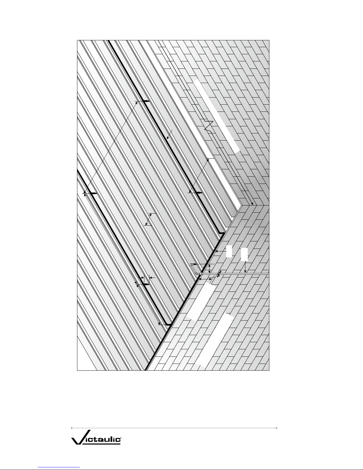
All system mains must run perpendicular to the joists, and all branch lines must run 4.
parallel to the joists.
CEILING
BLOCKING
16
inches
2 x 10 or 2 x 12
Solid Wood
Joists (Typical)
When the total protected area exceeds 1,000 square feet, blocking must be used 5.
in-between the joists to divide the area into sections; these sections must not exceed
1,000 square feet. Refer to the drawing above.
The maximum length along the joist must not exceed 32 feet. If the length exceeds
6.
32 feet, blocking must be used. The blocking must be constructed of minimum ½-inch
plywood and must be equal to the full depth of the wood joists.
Listed, residential-pendent sprinklers with a maximum temperature rating of 155°F
7.
and a minimum K-factor of 3.0 must be used for this type of installation. NOTE: The
maximum sprinkler spacing must not exceed 12 feet.
The system must be designed to UL Listed flows for the sprinkler being used.
8.
However, the flow must not be less than 11 gpm per sprinkler. Sprinklers must be
installed with the deflectors below the solid wood joists for future installation of a finished
ceiling. However, deflector placement must not exceed 1
¾ inches below the solid wood
joist in anticipation of a future finished ceiling installation (refer to Figures “B” and
“C” below). For more information, refer to NFPA 13D, “Standard for the Installation of
Sprinkler Systems in One-and Two-Family Dwellings and Manufactured Homes.”
Branches Supported with Blocking Branches Supported with Hangers
½ Joist
Depth Max.
1¾" Max.
FIGURE “B”
½ Joist
Depth Max.
1¾" Max.
FIGURE “C”
When installing Victaulic FireLock CPVC Sprinkler System Products perpendicular
9.
(system mains) to solid wood joists, UL Listed support devices must be used to mount
the piping directly to the bottom of the solid wood joists. In addition, it is acceptable to
cut holes in the solid wood joists at or below the center depth of the solid wood joist for
support. Holes must be oversized to allow for movement and must be located in an area
that will not compromise joist integrity. Contact the local authority having jurisdiction for
information regarding structural integrity.
Page 17

I-800_15
FIRELOCK CPVC SPRINKLER
SYSTEM PRODUCTS REV_J
When installing Victaulic FireLock CPVC Sprinkler System Products parallel (branch 10.
lines) to solid wood joists, the pipe and fittings must be installed in the cavity below the
bottom of the ceiling and above the bottom of the joist. Branch lines must be located
at or below the center depth of the solid wood joist. UL Listed support devices must be
used to mount the piping directly to nominal 2-inch wood blocking. In addition, UL Listed
support devices can be used that offset the pipe a nominal distance of 1
½ inches from
the solid wood joists.
System Risers (Protected and Exposed):
Victaulic FireLock CPVC Sprinkler System Products are UL Listed for use as system risers
in accordance with NFPA 13R and NFPA 13D with the following limitations.
A. CPVC risers must be installed in accordance with NFPA 13, “Support of Risers.”
B. When the system riser is installed protected (concealed), the minimum protection
must consist of one layer of
⁄-inch gypsum wallboard or ½-inch plywood. Refer to the
“Hanger/Support Spacing” section for detailed installation instructions for riser supports.
C. When the system riser is installed without protection (exposed), the following
limitations apply. NOTE: Only NFPA 13R and NFPA 13D applications can be installed
exposed.
The riser must be installed below a smooth, flat, horizontal ceiling construction. •
A UL Listed, residential-pendent sprinkler must be located in accordance with its
Listing and must be installed at a maximum horizontal distance of 12 inches from
the centerline of the riser. Refer to Figure “A” on page 16.
– OR –
The riser must be installed below a horizontal, unfinished basement ceiling in •
accordance with NFPA 13D. The unfinished basement ceiling must be constructed
of nominal 2-inch x 10-inch or 2-inch x 12-inch exposed solid wood joists on
16-inch centers. Refer to Figure “A” on page 16.
When installing Victaulic FireLock CPVC Sprinkler System Products in constructions
1.
with 2-inch x 12-inch solid wood joists, the maximum system working pressure under
flowing conditions must not exceed 100 psi. The maximum system working pressure
under static (non-flowing) conditions must not exceed 175 psi.
A UL Listed residential-pendent sprinkler with a maximum temperature rating of
2.
155ºF and a minimum K-factor of 3.0 is required at a maximum horizontal distance of 12
inches from the centerline of the riser. The deflector must be a maximum of 1
¾ inches
below the bottom of the solid wood joist; this is in anticipation of a future finished ceiling.
The system must be designed to UL Listed flows for the sprinkler being used. However,
the flow must not be less than 11 gpm per sprinkler.
The riser must be supported vertically within 2 feet from the ceiling or bottom of the
3.
joist.
UL Listed riser pipe sizes must be between 1 inch and 2 inches inclusive.
4.
The maximum distance between the walls and the outside surface of the riser pipe 5.
must be 1 ½ inches. Refer to Figure “A” on page 16.
Solvent cemented joints may be made with Victaulic Style #899 FireLock CPVC
6.
One-Step Solvent Cement or any of the solvent cement products listed in this manual.
These installations require the use of Schedule 80 fittings for risers that are 1
7. ½
inches and larger.
Page 18
I- 80 0_16
FIRELOCK CPVC SPRINKLER
SYSTEM PRODUCTS REV_J
32 feet Maximum to Wall or Blocking
1½ inches Maximum from
Wall to Edge of Riser
2 feet Maximum
to Support
12 inches Maximum to Center of Riser
12 feet Maximum
6 feet Maximum
6 feet Maximum
2 x 10 or 2 x 12
16-inch centers
1¾ inches Max.
Branch
Main
Riser
Figure “A”
Page 19
I- 800_17
FIRELOCK CPVC SPRINKLER
SYSTEM PRODUCTS REV_J
Garage Installations:
Victaulic FireLock CPVC Sprinkler System Products are suitable for use in garages
requiring sprinklers, as defined in NFPA 13R, with the following requirements:
Minimum protection consisting of either one layer of
1. ⁄-inch thick gypsum or
½-inch thick plywood must be provided.
Listed pendent or sidewall sprinklers with a maximum temperature rating of 225°F
2.
must be used.
All sprinklers must be installed per the manufacturer’s published installation
3.
instructions.
The system must be installed per the requirements of NFPA 13R and these
4.
installation instructions.
High Temperature Areas:
Victaulic FireLock CPVC Sprinkler System Products are suitable for use in areas •
where ambient temperatures are within the range of 35°F to 150°F.
Victaulic FireLock CPVC Sprinkler System Products can be installed in areas, such •
as an attic, where the ambient temperature exceeds 150°F if ventilation is provided
or if insulation is used around the product to maintain a cooler environment.
WARNING
DO NOT install Victaulic FireLock CPVC Sprinkler System Products in an area •
where the ambient temperature will exceed 150°F, unless ventilation is provided
or insulation is used around the product.
Failure to follow this instruction could result in significant property damage and
product damage.
Page 20
I-800_18
FIRELOCK CPVC SPRINKLER
SYSTEM PRODUCTS REV_J
Cold Temperature Areas:
Victaulic FireLock CPVC Sprinkler System Products can be used if the ambient •
temperature remains above 35°F.
In addition, these products can be used if the installation is in an area subject •
to freezing temperatures; however, the sprinkler system must be protected from
freezing. Many standard cold weather piping design and installation practices can
be used to protect the system from freezing, including, but not limited to, the use
of glycerin, insulation installation techniques, and pipe insulation. Contact Victaulic
with questions concerning compatibility. NOTE: Attention must be given to local
insulating techniques and codes that require a particular method.
Antifreeze solutions of water and USP or CP grade GLYCERIN are acceptable for use •
with Victaulic FireLock CPVC Sprinkler System Products. Refer to NFPA 13, NFPA
13R, and NFPA 13D.
WARNING
DO NOT allow a sprinkler system to freeze. A frozen system will deactivate, and •
the pressure can damage pipe or cause sprinklers to open.
DO NOT use glycol-based antifreeze solutions. Glycol solutions are not •
chemically compatible with the CPVC material and can cause damage to the
Victaulic FireLock CPVC Sprinkler System.
Failure to follow this instruction can result in serious personal injury, property
damage, and product damage.
Consult the local authority having jurisdiction before using glycerin solutions in fire
sprinkler applications. Since very cold weather will make Victaulic FireLock CPVC
Sprinkler System Products more susceptible to damage, extra care should be taken to
avoid rough handling or impact to these products.
The following information can be used to determine the quantity of an antifreeze solution
needed to protect the piping system.
Pipe Size
Gallons of Water/Foot
Nominal
Diameter
inches/mm
Actual Outside
Diameter
inches/mm
¾ 1.050
.0311
20 26.9
1 1.315
.0494
25 33.7
1 ¼ 1.660
.0792
32 42.4
1 ½ 1.900
.1042
40 48.3
2 2.375
.1636
50 60.3
* Note: The gallons per foot column can be used for calculations when adding GLYCERIN to the piping
system for freeze protection. All fire protection systems winterized with glycerin solutions must conform
to local, state, and NFPA requirements. Glycerin based solutions are the only antifreeze solutions
recommended for use. Glycol solutions are not chemically compatible with the CPVC material, and their
use may result in damage to the Victaulic FireLock CPVC Sprinkler System.
Page 21

I-800_19
FIRELOCK CPVC SPRINKLER
SYSTEM PRODUCTS REV_J
Underground Fire Service:
Victaulic FireLock CPVC Sprinkler System Products are UL Listed for use in underground
water service when installation is in accordance with:
ASTM-D2774, “Standard Recommended Practice for Underground Installation of •
Thermoplastic Pressure Piping”
ASTM-F645, “Standard Guide for Selection, Design and Installation of Thermoplastic •
Water Pressure Piping Systems”
NFPA 24, “Standard for the Installation of Private Fire Service Mains and Their •
Appurtenances”
The installation procedures detailed in this manual apply to Victaulic FireLock CPVC
Sprinkler System Products with solvent cemented joints in sizes
¾ inch through 2 inches.
Factory Mutual:
Victaulic FireLock CPVC Sprinkler System Products are FM Approved for use only in wet
pipe systems, as defined in:
Light Hazard occupancies, as defined in NFPA 13, “Standard for the Installation of •
Sprinkler Systems”
Residential occupancies, as defined in NFPA 13R, “Standard for the Installation of •
Sprinkler Systems in Residential Occupancies Up to and Including Four Stories in
Height”
Residential occupancies, as defined in NFPA 13D, “Standard for the Installation of •
Sprinkler Systems in One and Two-Family Dwellings and Manufactured Homes”
Underground fire service systems, as defined in NFPA 24, “Standard for the •
Installation of Private Fire Service Mains and Their Appurtenances”
Concealed Installations
Minimum protection shall be a permanently installed, non-combustible barrier •
that cannot be removed without substantial cosmetic damage. Drop-in ceiling tiles
used in suspended ceilings are not to be considered permanently installed for the
purposes of this definition.
Victaulic FireLock CPVC Sprinkler System Products are FM Approved for use with •
Fire Resistant Barriers for CPVC Pipe and Fittings in Light Hazard Occupancies
under FM Approval of the Soffi-Steel™ System manufactured by Grice Engineering,
Inc. Installation is to be made in accordance with the FM Approval requirements for
the Soffi-Steel™ System.
Exposed Installations
Victaulic FireLock CPVC Sprinkler System Products are FM Approved for exposed •
environments in Light Hazard Occupancies.
Where piping is installed above drop-in ceiling tiles, it shall be considered exposed.•
Piping may be installed under combustible or non-permanently installed smooth, •
flat, horizontal ceilings.
Piping shall be installed according to the information in this manual, and the •
sprinklers shall be FM Approved.
NSF® International:
Victaulic FireLock CPVC Sprinkler System Products are approved by NSF International for
potable water applications. These products meet all applicable performance standards
for a pressure rated application, as required in ANSI/NSF Standard 14, and they comply
with ANSI/NSF Standard 61 for health effects. Victaulic FireLock CPVC Sprinkler System
Products carry the NSF-pw end-use marking. Victaulic FireLock CPVC pipe and fittings
conform to ASTM-F438 and ASTM-F442 requirements. In addition, Victaulic Style #899
FireLock CPVC One-Step Solvent Cement meets ASTM-F493 and NSF International
requirements.
Page 22

I-800_20
FIRELOCK CPVC SPRINKLER
SYSTEM PRODUCTS REV_J
Penetrating Fire-Rated Walls and Partitions:
Before beginning, consult the building codes and authorities having jurisdiction in your
area. Several UL Classified, through-penetration firestop systems are approved for use
with CPVC pipe. Consult the UL Building Materials Directory, the UL Fire Resistance
Directory, and the system manufacturer for proper selection and application. Two
manufacturers of Listed systems for use with CPVC pipe are Nelson Fire Stop Products
(800 -331-7325) and Tremco (800-321-7906). Contact Victaulic for further information.
Heat Sources and Open Ceiling Areas:
Victaulic FireLock CPVC Sprinkler Systems must be laid out so that the piping is not closely
exposed to heat producing sources, such as light fixtures, ballasts, and steam lines. Pipe
must not be positioned directly over open ventilation grills. During remodeling or ceiling
repair, appropriate precautions must be implemented to properly protect the piping.
Use with Other Manufacturers’ Pipes, Fittings,
and Solvent Cements:
Victaulic FireLock CPVC Sprinkler System Products are UL Listed for use in combination
with UL Listed CPVC sprinkler products manufactured by Central (pipe and fittings),
Harvel (pipe), Ipex (pipe and fittings), Tyco Fire Products (pipe and fittings), Spears
(fittings), Thompson Plastics (fittings), Viking (pipe), or Nibco (fittings).
Victaulic recommends the use of Victaulic Style #899 FireLock CPVC One-Step Solvent
Cement. However, Spears FS-5; Ipex BM-5; Tyco Fire Products TFP-500; Thompson
Plastics, Inc. TPI-50; and Central Sprinkler CSC-500 CPVC Solvent Cements can also be
used in place of Victaulic Style #899 FireLock CPVC One-Step Solvent Cement, provided
that the assembly and curing information referenced within this manual is used. Contact
Victaulic at 1-800 -PICK VIC (1-800-742-5842) for further information on Listings and
Approvals.
NOTICE
The “Victaulic FireLock CPVC Sprinkler System Products Warranty” applies only •
to products supplied by Victaulic. Refer to the “Warranty” section in this manual
for details.
Page 23

I- 800_21
FIRELOCK CPVC SPRINKLER
SYSTEM PRODUCTS REV_J
INSTALLATION & JOINING SECTION
Cutting the Pipe:
Victaulic FireLock CPVC Sprinkler System pipe can be cut easily with a ratchet cutter,
wheel-type plastic tubing cutter, a power saw, or any other fine-tooth saw. Tools used to
cut CPVC must be designed for plastic use and must be in good condition, in accordance
with the tool manufacturer’s recommendations. It is important to cut the pipe square. A
square cut provides the surface of the pipe with maximum bonding area.
If any indication of damage or cracking is evident at the pipe end, cut off at least 2
inches beyond any visible crack.
CAUTION
Care must be exercised if using ratchet cutters, since they may split the pipe if •
not used and maintained properly.
Use only ratchet cutters that contain a sharp blade (blades dull quickly)•
Use only ratchet cutters at temperatures of 50° F or warmer.•
Use only good quality ratchet cutters capable of producing consistent, square •
cuts.
Failure to follow these instructions could result in leakage and property damage.
Be careful not to split the pipe if a ratchet-type cutter is being used, especially in •
temperatures below 50°F. If any damage or cracking is evident, cut off at least 2
inches of the pipe beyond any visible crack.
It is important that the cutting tools and blades being used are designed for plastic •
pipe. To ensure that the pipe is cut square, use a miter box when cutting the pipe
with a saw. Cutting the pipe as square as possible provides the maximum bonding
surface area.
Page 24

I-800_22
FIRELOCK CPVC SPRINKLER
SYSTEM PRODUCTS REV_J
Deburring and Beveling:
Burrs and filings can prevent proper contact between the pipe and fitting during •
assembly and must be removed from the pipe inside and outside diameters. A
chamfering tool or file is suitable for deburring pipe.
A slight bevel (approximately 10° to 15°) shall be placed at the end of the pipe to •
ease entry of the pipe into the fitting socket. A bevel on the pipe end will minimize
the amount of solvent cements that is wiped from the fitting socket during insertion.
Fitting Preparation:
WARNING
Before assembling any Victaulic FireLock CPVC Sprinkler System Products, all •
components must be inspected for cuts, scratches, gouges, split ends, or any
other irregularities that have occurred during shipping and handling.
Failure to check all products for damage before installation could result in
significant property damage, joint failure, and/or joint leakage.
The pipe should enter the fitting socket easily •
⁄ to ⁄ of the way. Contact between
the pipe and fitting is essential for assembling a good joint. This contact allows the
solvent cement, which is applied in the following step, to effectively join the pipe and
fitting.
Using a clean, dry rag, wipe all loose dirt and moisture from the fitting socket and •
pipe end. Moisture can slow the cure time and, at this stage of assembly, excessive
water can reduce joint strength.
Page 25

I-800_23
FIRELOCK CPVC SPRINKLER
SYSTEM PRODUCTS REV_J
Solvent Cement Application:
WARNING
Before using Victaulic Style #899 FireLock CPVC One-Step Solvent Cement, •
refer to ASTM– F402, “Standard Practice for Safe Handling of Solvent Cements,
Primers, and Cleaners Used for Thermoplastic Pipe and Fittings;” the Material
Safety Data Sheet (MSDS) for the solvent cement; and the important product
information contained on the solvent cement can label.
Victaulic Style #899 FireLock CPVC One-Step Solvent Cement is highly •
flammable. Make sure all ignition sources are eliminated before use.
Avoid breathing solvent cement vapors, and use solvent cement only in well-•
ventilated areas. Explosion-proof, general mechanical ventilation or local exhaust
is recommended to maintain vapor concentrations below recommended exposure
limits. In confined or partially enclosed areas, a NIOSH-approved, organic-vapor
cartridge respirator with a full-face piece is recommended.
Avoid frequent contact with skin. PVA coated gloves and an impervious apron •
are recommended.
Avoid contact with eyes. Splash-proof chemical goggles are recommended.•
Failure to follow these instructions could result in serious personal injury.
CAUTION
DO NOT use solvent cement that exceeds 2 years from the date stamped on the •
container.
DO NOT use solvent cement that has a “JELLED” appearance.•
Jelled or expired cement will not provide the required strength for a proper joint
and can result in joint failure and/or property damage.
Before assembling any Victaulic FireLock CPVC Sprinkler System Products, verify •
the expiration date located on the Style #899 FireLock CPVC One-Step Solvent
Cement container. Solvent cement can be used for a period of 2 years from the date
stamped on the container. DO NOT use solvent cement that exceeds 2 years from
the date stamped on the container. Expired solvent cement must be discarded in an
environmentally friendly fashion, in accordance with local regulations.
Special care shall be exercised when assembling Victaulic FireLock CPVC Sprinkler •
System Products in temperatures below 40° F. In colder temperatures, extra time
must be allowed for the solvent cement to set. Extra care should be taken to prevent
damaging the pipe during handling. When applying cement to pipe and fittings in
colder temperatures, make sure the cement does not become “lumpy” or “gelled”.
Lumpy or gelled cement must be discarded in an environmentally-friendly fashion, in
accordance with local regulations.
At temperatures above 80° F, make sure both surfaces to be joined are still wet •
with cement during assembly. Higher temperatures and/or wind accelerate the
evaporation of the volatile solvents in the cement. Pipe stored in direct sunlight may
have surface temperatures of 20° F to 30° F above the air temperature. If possible,
store the pipe and fittings (or at minimum the ends to be solvent cemented) out of
direct sunlight prior to applying cement. The solvents will penetrate hot surfaces
more deeply and, in higher temperatures, it is very important to avoid puddling
solvent cement inside the fitting socket.
To prolong the life of solvent cement, keep containers tightly closed when not in use. •
Cover the container as much as possible during use.
Page 26

I-800_24
FIRELOCK CPVC SPRINKLER
SYSTEM PRODUCTS REV_J
If an unopened solvent cement container is subjected to freezing temperatures, •
the cement may become extremely thick. Place the closed container in a room
temperature area where, after a short time period, the cement will return to a usable
condition. DO NOT attempt to heat solvent cement. Contact Victaulic at
(800) PICK VIC or (800) 742-5842 with any questions concerning usability.
Use only solvent cements that have been formulated and listed/approved specifically •
for use with CPVC fire sprinkler systems and that have been approved by the pipe
and fitting manufacturers.
Use a dauber that is sized properly for the pipe. For •
¾-inch and 1-inch pipe sizes,
use a dauber that is
½-inch in size. For 1 ¼-inch through 2-inch pipe sizes, use a
dauber that is
¾-inch in size. Refer to the photos and steps below for the proper
application sequence.
Excess solvent cement can cause clogged waterways. DO NOT allow excess cement •
to puddle in the pipe and fitting assembly. To prevent puddling, the inside of the
fitting socket should receive a lighter coating of solvent cement than the outside of
the pipe. Excess solvent cement on the outside of the pipe should be wiped off. The
solvents will evaporate, but the cement inside the fitting will remain.
CAUTION
Improper installation techniques that result in excess solvent cement will weaken •
the wall of the CPVC pipe or fitting.
Failure to follow proper installation techniques may result in system leakage and
property damage.
Vigorously apply a heavy, even coat of cement to the outside of the pipe end. Work 1.
the cement into the joining surfaces using a continuous, circular motion.
Apply a medium coat to the fitting socket. Avoid getting cement into other sockets 2.
or threaded connections.
Page 27

I-800_25
FIRELOCK CPVC SPRINKLER
SYSTEM PRODUCTS REV_J
A second application of solvent cement shall be applied to the pipe end in the same 3.
manner as described in step 1 on the previous page. DO NOT apply a second coat of
solvent cement to the fitting socket.
WARNING
Follow all instructions contained in this manual when solvent cementing •
Victaulic FireLock CPVC Sprinkler System Products.
Too much solvent cement can cause clogged waterways or pipe failure.•
DO NOT allow excess solvent cement to puddle in the pipe and fitting assembly.•
To prevent puddling, the inside of the fitting socket should receive a lighter •
coating of solvent cement than the outside of the pipe.
Excess solvent cement on the outside of the joint should be wiped off and the •
solvents allowed to evaporate. However, the solvent cement inside the fitting will
remain.
Improper installation techniques that involve too much solvent cement will weaken
the wall at the pipe or fitting, resulting in leakage and/or significant property
damage.
Page 28

I-800_26
FIRELOCK CPVC SPRINKLER
SYSTEM PRODUCTS REV_J
Assembly:
After applying solvent cement, insert the pipe into the fitting socket immediately, •
while rotating the pipe a quarter turn until the pipe bottoms out at the fitting stop. At
this time, align the fitting properly for the installation. The pipe must bottom out at
the fitting stop. Hold the assembly for 30 seconds to ensure initial bonding. A bead
of solvent cement should be evident around the pipe and fitting juncture. If a bead
of solvent cement is not continuous around the socket shoulder, this may be an
indication that insufficient solvent cement was applied. If insufficient solvent cement
was applied, the fitting must be cut out and discarded. Cement in excess of the
bead should be wiped off with a clean, dry rag.
Care shall be exercised when installing sprinklers. Sprinkler fittings shall be allowed •
to cure a minimum of 30 minutes before attempting to install the sprinkler. When
installing sprinklers, anchor or hold the pipe drop securely to avoid rotating the pipe
in previously cemented connections. Previously cemented fittings shall be permitted
to cure a minimum of 30 minutes.
CAUTION
Sprinklers shall be installed only after all CPVC pipe and fittings, including the •
sprinkler adapters, are solvent cemented and allowed to cure a minimum of 30
minutes.
Sprinkler fittings should be visually inspected to ensure that the waterway and •
threads are clear of any excess solvent cement.
When the installation is complete and cured (per Tables 1, 2, or 3 in the “Set •
and Cure Times” section in this manual), the system shall go through system
acceptance testing (hydrostatic pressure testing).
Sprinklers shall not be installed in the fitting prior to the fittings being solvent •
cemented in place.
Failure to follow these instructions could cause system failure, resulting in property
damage.
Set and Cure Times:
Solvent cement set and cure times are a function of pipe size, temperature, relative
humidity, and tightness of fit. Curing time is faster for drier environments, smaller pipe
sizes, higher temperatures, and tighter fits. Curing times should be increased when
moisture is present, such as during cut-ins to active sprinkler lines. NOTE: A specific
procedure for modifications or repairs to existing CPVC fire sprinkler lines is included in
the “Cut-In Procedures for System Modification or Repair” section in this manual. The
assembly must be allowed to set without any stress on the joint for 5 minutes, depending
on pipe size and temperature. Following the initial set period, the assembly can be
handled carefully, avoiding significant stresses to the joint. Refer to the tables on the
following page for the minimum cure times prior to pressure testing. In addition, refer to
the “Solvent Cement Application” section in this manual.
Page 29

I-800_27
FIRELOCK CPVC SPRINKLER
SYSTEM PRODUCTS REV_J
Minimum Cure Times for Victaulic
Style #899 FireLock CPVC One-Step Solvent Cement Prior to
Pressure Testing
Table 1 – 225-psi (Maximum) Test Pressure
Size Ambient Temperature During Cure
Nominal Diameter
inches/mm
Actual Outside
Diameter
inches/mm 60°F to 120°F 40°F to 59°F 0°F to 39°F
¾ 1.050
1 hour 4 hours 48 hours
20 26.9
1 1.315
1 ½ hours 4 hours 48 hours
25 33.7
1 ¼ & 1 ½ 1.660 & 1.900
3 hours 32 hours 10 days
32 & 40 42.4 & 48.3
2 2.375
8 hours 48 hours Note 1
50 60.3
Table 2 – 200-psi (Maximum) Test Pressure
Size Ambient Temperature During Cure
Nominal Diameter
inches/mm
Actual Outside
Diameter
inches/mm 60°F to 120°F 40°F to 59°F 0°F to 39°F
¾ 1.050
45 minutes 1 ½ hours 24 hours
20 26.9
1 1.315
45 minutes 1 ½ hours 24 hours
25 33.7
1 ¼ & 1 ½ 1.660 & 1.900
1 ½ hours 16 hours 120 hours
32 & 40 42.4 & 48.3
2 2.375
6 hours 36 hours Note 1
50 60.3
Note 1: Solvent cement can be applied at temperatures below 40°F for all sizes. For the 2-inch size, the
temperature must be raised to 4 0°F or above and allowed to cure per the recommended times before
the system is filled and pressurized.
Table 3 – 100-psi (Maximum) Test Pressure
Size ‡ Ambient Temperature During Cure
Nominal Diameter
inches/mm
Actual Outside
Diameter
inches/mm 60°F to 120°F 40°F to 59°F 0°F to 39°F
¾ 1.050
15 minutes 15 minutes 30 minutes
20 26.9
1 1.315
15 minutes 30 minutes 30 minutes
25 33.7
1 ¼ 1.660
15 minutes 30 minutes 2 hours
32 42.4
‡ 1 ½-inch and larger sizes must be tested ONLY in accordance with Table 1 and Table 2.
Page 30

I-800_28
FIRELOCK CPVC SPRINKLER
SYSTEM PRODUCTS REV_J
WARNING
Make sure the cement is allowed to cure according to the times listed in the •
charts for the pipe size and ambient temperature. These cure times have been
tested and approved for Victaulic FireLock CPVC Sprinkler System Products.
DO NOT install any sprinklers until the piping system has cured for a minimum •
of 30 minutes.
Solvent cement set and cure times are a function of pipe size, temperature, •
relative humidity, and tightness of fit.
Curing time is faster for drier environments, smaller pipe sizes, higher •
temperatures, and tighter fits.
Cure times should be increased when moisture is present, such as during cut-ins •
to active sprinkler lines.
Failure to follow these instructions could cause improper system operation or
leakage, resulting in property damage.
The following guidelines provide an estimate of the quantities of Victaulic Style #899
FireLock CPVC One-Step Solvent Cement that will be required to complete the assembly.
Solvent Cement Requirements
Size Solvent Cement
Nominal Diameter
inches/mm
Actual Outside Diameter
inches/mm
Number of Joints
Per Quart (estimated)
¾ 1.050
270
20 26.9
1 1.315
180
25 33.7
1 ¼ & 1 ½ 1.660 & 1.900
130
32 & 40 42.4 & 48.3
2 2.375
100
50 60.3
WARNING
Make sure all assembly and curing times, outlined in this manual, are followed •
when installing Victaulic FireLock CPVC Sprinkler System Products.
Failure to follow this instruction could cause improper joint assembly and joint
failure, resulting in significant property damage and/or serious personal injury.
Threaded Connections:
Threaded connections require application of a thread sealant that has been tested
and approved for use with CPVC material. Victaulic recommends the use of Spears
Manufacturing Blue 75 Thread Sealant or IPS Weld-On Teal Seal. These products
have been tested specifically for compatibility with Victaulic FireLock CPVC Sprinkler
System Products. However, it is important to contact the sprinkler manufacturer to verify
chemical compatibility with their products.
In addition, cutting oils used while threading metal pipe can cause stress cracks in CPVC
material. Before making threaded connections, threaded metal pipe must be flushed and
degreased to remove cutting oil.
Victaulic strongly recommends the pastes listed above; however, tape can be used,
provided the following requirements are followed. NOTE: Tape sealant must be used
properly to prevent “wedging” of tapered pipe threads, which can cause joint failure due
Page 31

I-800_29
FIRELOCK CPVC SPRINKLER
SYSTEM PRODUCTS REV_J
to excessive stress on the fitting. DO NOT USE A COMBINATION OF PASTE AND TAPE
ON THREADED CONNECTIONS.
The thickness of the tape • MUST be a minimum of 25 mil. Tape less than 25-mil
thick will not provide sufficient sealing.
The initial wrap of tape • MUST fully cover the end of the threads. Failure to fully
cover the end of the threads can cause seizing of the threads, which produces a
false sense of tightening the joint properly. Additional attempts to tighten a joint with
seized threads can cause damage to the pipe and fittings.
Tape • MUST be wrapped CLOCKWISE for standard pipe threads. Tape that is
wrapped in the wrong direction will bunch and create uneven sealing.
DO NOT EXCEED 2 – 3 OVERLAPPING WRAPS OF TAPE.• Excess tape increases
the male thread diameter and causes stress to the joint.
Apply sealant to the male threads only. Make sure all threads are covered. DO NOT
1.
clog the waterway with excessive sealant.
Thread the sprinkler into the fitting by hand until finger-tight.
2.
To tighten the sprinkler completely into the fitting, use an adjustable wrench on 3.
the flats of the sprinkler adapter and a sprinkler wrench designed specifically for the
sprinkler. When a pipe wrench is used, Victaulic recommends the use of a smooth-jawed
wrench or a strap wrench when installing threaded connections. DO NOT use tools with
teeth or conventional pipe wrenches on any part of a fitting for CPVC pipe.
DO NOT over-torque threaded connections. Generally, one to two turns beyond
4.
finger-tight are required to make a threaded connection. Factory testing indicates
10 ft-lbs minimum to 25 ft-lbs maximum of torque for obtaining a proper seal.
Sprinklers must be installed only after all fittings, including sprinkler adapters, are
5.
cemented to the piping and have been allowed to cure for a minimum of 30 minutes.
Plastic threaded plugs are available for use during pressure testing. Before sprinklers are
installed, all fittings must be visually inspected or probed with a wooden dowel to ensure
the waterway and threaded areas do not contain excessive cement that may restrict
water flow.
CAUTION
Use only thread sealants recommended by Victaulic. Use of any other thread •
sealants may cause stress cracks in fittings for CPVC pipe. Contact Victaulic
with any questions concerning compatibility of thread sealants with Victaulic
FireLock CPVC Sprinkler System Products.
DO NOT use a combination of paste and tape on threaded connections.•
DO NOT over-torque threaded connections.•
DO NOT use tools with teeth on any part of a CPVC fitting. Tools with teeth can •
damage and weaken CPVC material.
Failure to follow these instructions could cause product damage and joint leakage,
resulting in property damage.
Page 32

I-800_30
FIRELOCK CPVC SPRINKLER
SYSTEM PRODUCTS REV_J
Transition to Other Materials:
Specifically designed female threaded adapters, grooved coupling adapters, and flanges
are UL Listed for connecting a Victaulic FireLock CPVC Sprinkler System to other
materials, valves, and accessories. A special, reinforced female threaded adapter is
available for connection to the sprinkler.
Flange Connections:
When using Victaulic supplied Spears® CPVC flange adapters, follow the instructions
below. Piping runs joined to the flanges must be installed in a straight line in relation
to the flange to avoid stress at the flange due to misalignment. In addition, piping must
be secured and supported to prevent lateral movement, which can create stress and
damage the flange.
FLANGE MAKEUP: Once a flange is joined to the pipe, the method for joining two
flanges is as follows:
A. With the gasket in place, align the bolt holes of the mating flanges by rotating the
ring into position.
NOTICE
Consideration should be given to aligning the one-piece flange before joining it •
with the pipe.
B. Insert all bolts, flat washers (place one washer under the bolt head and one under
the nut), and nuts. NOTE: Victaulic does not supply bolts, nuts, washers, and gaskets.
C. Make sure the faces of the mating surfaces are flush against the gasket before
bolting down the flanges.
D. Tighten the nuts by hand until they are snug. Establish uniform pressure over the
flange face by tightening the nuts in 5 ft-lb increments, according to the sequence shown
below in Figure 1.
1
2
3
4
Figure 1
E. Care must be taken to avoid bending the flange when joining a standard flange to a
“raised face” flange or a wafer-style valve.
CAUTION
DO NOT use the bolts to bring together improperly mated flanges.•
DO NOT over-torque the flange. Too much torque will damage the flange.•
Make sure the proper lubricant is used on the bolts, and insert one flat washer •
under the bolt head and one under the nut.
Failure to follow this instruction could result in property damage, product damage,
joint leakage, and/or joint failure.
Page 33

I- 800_31
FIRELOCK CPVC SPRINKLER
SYSTEM PRODUCTS REV_J
The following recommendations are based on the use of two standard flat washers,
standard nuts, and an
⁄-inch thick EPDM full-face gasket. Actual field conditions may
require a variation in these recommendations.
Size Recommended Torque
Nominal Diameter
inches/mm
Actual Outside Diameter
inches/mm ft-lbs
¾ – 1 ½ 1.050 – 1.900
12
20 – 40 26.9 – 48.3
2 2.375
25
50 60.3
Size Bolt Diameter
Minimum Bolt
Length
Nominal Diameter
inches/mm
Actual Outside
Diameter
inches/mm Bolt Holes inches inches
¾ 1.050
4 ½ 2
20 26.9
1 1.315
4 ½ 2 ¼
25 33.7
1 ¼ 1.660
4 ½ 2 ¼
32 42.4
1 ½ 1.900
4 ½ 2 ½
40 48.3
2 2.375
4 ⁄ 3
50 60.3
Page 34

I-800_32
FIRELOCK CPVC SPRINKLER
SYSTEM PRODUCTS REV_J
Grooved Connections:
WARNING
Read the following instructions carefully before installation occurs. The following •
instructions are required for proper assembly of Victaulic FireLock CPVC
No. 832 Grooved Adapters to grooved Iron Pipe Size (IPS) pipe and valves.
DO NOT use Victaulic Style 005 and Style 07 Rigid Couplings with Victaulic •
FireLock CPVC No. 832 CPVC Grooved Adapters. These style couplings may
damage the grooved adapter. Contact Victaulic with any questions concerning
proper coupling selection.
DO NOT attempt to direct groove Victaulic FireLock CPVC Sprinkler System •
Pipe.
Failure to follow these instructions could cause improper product installation,
resulting in serious personal injury and/or property damage.
Victaulic FireLock CPVC No. 832 Grooved Adapters are designed for use with Victaulic
Style 75 and Style 77 Flexible Couplings. DO NOT ATTEMPT TO DIRECT GROOVE
CPVC PIPE. THE VICTAULIC FIRELOCK CPVC NO. 832 GROOVED ADAPTER MUST
BE USED WHEN MAKING A TRANSITION FROM VICTAULIC FIRELOCK CPVC
SPRINKLER SYSTEM PIPE TO GROOVED IPS PIPE. DO NOT USE VICTAULIC STYLE
005 AND STYLE 07 RIGID COUPLINGS WITH VICTAULIC FIRELOCK CPVC NO. 832
GROOVED ADAPTERS.
Prepare the IPS pipe in accordance with current Victaulic specifications.
1.
Inspect the grooved adapter and pipe. The outside surface of the pipe/adapter 2.
groove and the pipe/adapter end must be smooth and free from indentations, projections,
and roll marks to ensure a leak-tight seal for the gasket. All oil, grease, and dirt must be
removed.
Use a standard Grade “E” (EPDM) gasket with a green stripe or a grade “E,” Type
3.
“A” gasket with a purple stripe that is suitable for wet fire protection service.
Make sure the gasket is clean and does not contain cracks, cuts, and other defects
4.
that could cause leaks. DO NOT allow solvent cement to contact the gasket.
Check the gasket supplied to make sure it is Vic-Plus™. It is normal for a fine, white
5.
“haze” to appear on the gasket surface when it is flexed. If the gasket is not supplied with
Vic-Plus, lubrication will be required. Lubricate the gasket with IPS Weld-On Gasket/Joint
Lubricant #787 or Seacord Corp. Ease-On Pipe Joint Lubricant.
CAUTION
DO NOT use Victaulic lubricant with Victaulic FireLock CPVC Sprinkler System •
Products.
Certain lubricants may contain petroleum or other chemicals that can damage •
the gasket or CPVC material. Contact Victaulic to verify the suitability of
lubricant before use.
Failure to follow these instructions could cause product damage, resulting in
property damage.
Install the gasket over the pipe end. Make sure the gasket lip does not overhang the
6.
pipe end.
Align the Victaulic FireLock CPVC No. 832 Grooved Adapter with the IPS pipe end.
7.
Slide the gasket into position, and make sure it is centered between the grooves in the
IPS pipe and the adapter. Make sure no portion of the gasket extends into the grooves.
Install the housings over the gasket. Make sure the housings’ keys engage the
8.
grooves properly on the IPS pipe and the adapter.
Page 35

I-800_33
FIRELOCK CPVC SPRINKLER
SYSTEM PRODUCTS REV_J
Install the bolts, and apply the nuts finger-tight. 9. NOTE: Make sure the bolt track
heads seat properly in the bolt holes.
Tighten all nuts evenly by alternating sides until metal-to-metal contact occurs at
10.
the bolt pads. Make sure the housings’ keys completely engage the grooves. NOTE: It is
important to tighten all nuts evenly to prevent gasket pinching.
WARNING
Victaulic flexible couplings must have the nuts tightened until metal-to-metal •
contact occurs at the bolt pads.
Failure to follow this instruction could cause joint failure, resulting in serious
personal injury and/or property damage.
Inspect the joints before and after pressure testing. Look for gaps between the
11.
bolt pads. Look for housing keys are that are not inside the grooves. Ensure that pipe
alignment does not place undue stress on the grooved adapter. If any of these conditions
are found, they must be corrected immediately.
The maximum recommended pipe hanger distance from the grooved adapter is
12.
shown in the following table.
Size
Maximum Recommended
Hanger Spacing
Nominal Diameter
inches/mm
Actual Outside Diameter
inches/mm feet
1 ¼ 1.660
6 ½
32 42.4
1 ½ 1.900
7
40 48.3
2 2.375
8
50 60.3
As an added precaution, and to enhance the structural design of the system,
13.
Victaulic suggests a hanger or support be located at or near the grooved adapter joint.
This hanger or support can be placed on either side of the coupling. However, this is
not a requirement, since the hanger spacing values, shown in the table above, meet
minimum UL requirements.
Page 36

I-800_34
FIRELOCK CPVC SPRINKLER
SYSTEM PRODUCTS REV_J
SYSTEM ACCEPTANCE TESTING
(HYDROSTATIC PRESSURE TEST)
When an installation is complete and joints are cured properly per the requirements listed
in this manual, the system should be pressure tested with water to 200 psi for 2 hours.
Refer to Table 2 in the “Set and Cure Times” section for curing conditions at 200 psi.
The system should be pressure tested with water to 50 psi in excess of the maximum
pressure when the maximum system pressure will be maintained above 150 psi. Refer to
Table 1 in the “Set and Cure Times” section for curing conditions at 225 psi. These tests
are in accordance with requirements established by NFPA Standard 13, Section 24.2.1
(2007 Edition).
Sprinkler systems in one- and two-family dwellings and mobile homes may be pressure
tested with water at line pressure, after following Table III curing conditions, in
accordance with the requirements established by NFPA 13D, Section 4.3 (2007 Edition).
When pressure testing, the sprinkler system shall be filled slowly with water. Air shall be
bled from the highest and furthest sprinkler heads before pressure testing is applied.
Air must be removed from the piping systems (plastic or metal) to prevent it from being
locked in the system when pressure is applied. Entrapped air can generate excessive
surge pressures that can result in death, serious personal injury, and property damage,
regardless of the piping material used.
If a leak is found, the fitting must be cut out and discarded. A new section can be
installed by using a coupling or a union. Unions should be used in accessible areas only.
WARNING
AIR OR COMPRESSED GAS MUST NEVER BE USED FOR SYSTEM •
ACCEPTANCE TESTING (HYDROSTATIC PRESSURE TESTING).
System failure when using compressed air/gas for system acceptance testing can
result in serious personal injury, death, and/or property damage.
Page 37

I-800_35
FIRELOCK CPVC SPRINKLER
SYSTEM PRODUCTS REV_J
PAINTING PIPE AND FITTINGS
The UL Listing DOES NOT cover painted CPVC fire sprinkler piping products. Use of
certain paints, such as oil-based, can damage CPVC fire sprinkler piping products.
Before painting any CPVC fire sprinkler piping products, consult with the local authority
having jurisdiction for restrictions, and contact the paint supplier to confirm compatibility
with CPVC material.
When cutting into a FireLock CPVC system that has been painted with compatible
water-based latex paint, the end of the pipe must be sanded with fine grain sand paper
to remove all traces of paint to approximately
½ inch beyond the end of the fitting to
be added. All material must be removed evenly, and the outside diameter of the pipe
must be measured to ensure it remains within the dimensions listed in the “Pipe and
Fitting Specification” section. If too much material is removed, leakage may result due
to inadequate contact between the pipe and fitting. Check the dry fit of the pipe within
the fitting. The pipe should enter the fitting socket easily fit
¼ to ¾ of the way. If the pipe
bottoms out during the dry fit, replace the fitting. Refer to the “Cut-In Procedures for
System Modification or Repair” section for complete instructions.
CAUTION
The UL Listing does not cover painted CPVC Sprinkler System Products.•
DO NOT use harsh chemicals to clean CPVC products.•
Failure to follow this instruction could result in significant property damage and
product damage.
Page 38

I-800_36
FIRELOCK CPVC SPRINKLER
SYSTEM PRODUCTS REV_J
CUT-IN PROCEDURES FOR SYSTEM
MODIFICATION OR REPAIR
WARNING
Depressurize and drain the piping system before performing any modifications or •
repairs to an existing system.
Failure to follow this instruction could cause serious personal injury and/or product
damage.
Victaulic FireLock CPVC Sprinkler System Products can be used to make modifications or
repairs to existing systems. Several fitting combinations can be used to tie into an existing
system or to replace a section between fixed, cut-in points. A socket tee can be used to
add onto an existing system. For repairing an existing system, a socket coupling can be
used in combination with a union, a grooved coupling adapter, or a flange.
Review all instructions in the “Installation & Joining Section” section before cutting •
into an existing system (including square cutting, deburring, beveling, cleaning, dryfit checks, etc.). The minimum cut-in cure times, listed in the table below, must be
followed to ensure proper assembly.
Depressurize and drain the piping system before performing any modifications or •
repairs to an existing system.
System modifications (cut-ins) should be made on the smallest diameter pipe •
section that is in close proximity to the area of modification. The selected section
must be capable of properly supplying the system change.
Carefully plan and measure the section before cutting into the existing system. •
Make sure adequate space is available to ensure full insertion of pipe into fitting
sockets. Make a dry connection to the existing system to check for proper fit before
proceeding with the solvent cementing procedure.
NOTICE
Allowance must be made for making a • ¼-turn twist when inserting the pipe
into the tee (or other component), especially on 1 ½ inch and larger pipe sizes.
This may require assembly of components in combination with the cut-in tee to
create a short spool piece for final connection using socket unions, flanges, or
grooved coupling adapters.
All dirt and residual moisture must be removed from all areas that will receive •
solvent cement. Vacuum the lines, and wipe dry with a clean, dry rag. Moisture and
dirt will slow curing times and can affect joint strength.
Only new cans of approved solvent cement should be used when making cut-in •
connections. Verify the expiration date on the solvent cement can before use.
Before pressure testing, the cut-in joint must be allowed to cure according to the •
times listed in the following chart.
Page 39

I-800_37
FIRELOCK CPVC SPRINKLER
SYSTEM PRODUCTS REV_J
Minimum Cut-In Cure Times
Size Ambient Temperature During Cure
Nominal Diameter
inches/mm
Actual Outside
Diameter
inches/mm 60°F to 120°F ‡ 40°F to 59°F 0°F to 39°F
¾ 1.050
24 hours 24 hours 48 hours
20 26.9
1 1.315
24 hours 24 hours 48 hours
25 33.7
1 ¼ 1.660
24 hours 32 hours 10 days
32 42.4
1 ½ 1.900
24 hours 32 hours 10 days
40 48.3
2 2.375
24 hours 48 hours Note 1
50 60.3
‡ Solvent cement, pipe, and fittings brought in from colder temperatures must be allowed to reach at
least 60°F before using these cure times.
Note 1: Solvent cement can be applied at temperatures below 40°F for all sizes. For the 2-inch and
larger sizes, the temperature must be raised to 40°F or above and must be allowed to cure per the
required times listed in this table before the system is filled and pressurized.
After the joint has properly cured, inspect the line for proper alignment and hanger •
placement before pressure testing.
Whenever possible, Victaulic recommends isolating the portion of the sprinkler •
system that contains the cut-in tee before pressure testing. The applied test
pressure MUST NOT exceed 50 psi over the system pressure in order to minimize
water damage in the event that leakage occurs.
To pressure test the system, slowly fill the system with water. Make sure all air is •
bled from the furthest and highest point before test pressure is applied. The system
MUST be pressure tested in accordance with NFPA 13, NFPA 24, or any other
applicable NFPA standard. The system must be tested with water. The purpose
of the hydrostatic pressure test is to check for leakage; this test may not identify
improperly assembled joints. This test MUST NOT be considered a substitute for full
compliance with the installation instructions published in this manual.
WARNING
Victaulic FireLock CPVC Sprinkler System Products must never be used or •
tested in a system that contains compressed air or other gases.
Air must be removed from piping systems. Entrapped air can generate excessive •
surge pressures.
Failure to follow these instructions could cause product failure, resulting in serious
personal injury and/or property damage.
Page 40

I-800_38
FIRELOCK CPVC SPRINKLER
SYSTEM PRODUCTS REV_J
ACCESSORIES
Pipe Hangers:
WARNING
Install the hangers with the screws provided.•
DO NOT use any hardware that requires the use of a hammer or power nailer.•
Failure to follow this instruction could result in personal injury, product damage,
and/or system leakage.
NOTICE
Refer to the “Engineering Data” section for recommended hanger spacing.•
Pipe hangers and support devices, used with Victaulic FireLock CPVC Sprinkler System
Products, must be listed as a UL Category VIXH (Support Devices for Thermoplastic
Sprinkler Piping) and/or VFXT (Hangers, Pipe). Refer to the UL website for manufacturers
of products that comply with these categories. In addition, these hangers must comply
with NFPA requirements for use with CPVC fire sprinkler piping systems. Hangers
must not compress, distort, cut, or abrade the piping, and they must allow free axial
movement of the pipe for thermal expansion and contraction. Ensure that the hangers
do not contain rough or sharp edges, which can damage the CPVC pipe. DO NOT use
any supporting devices that require the use of a hammer, power nailer, and/or nails for
installation. For hanging requirements, refer to the “Hanger/Support Spacing” section for
specific information.
Page 41

I-800_39
FIRELOCK CPVC SPRINKLER
SYSTEM PRODUCTS REV_J
CPVC One-Hole Wrap-Around Strap:
The CPVC one-hole wrap-around strap is designed to support CPVC piping systems
only when the hanger tab is in the vertical position and the screw-type fastener is in the
horizontal position. These straps can be used as pipe restraints when the hanger tab is
in the downward position; however, they cannot be used to support any weight of the
system. In addition, these straps can be used as piping system guides when the system
lies on top of a beam, and the beam supports the system’s weight.
The one-hole wrap-around strap is not intended to support the CPVC piping system from
underneath a ceiling or any other flat, horizontal surface. For this application, a CPVC
two-hole strap must be installed.
CPVC Two-Hole Strap:
The CPVC two-hole strap is designed to support CPVC piping systems when attached to
a flat, horizontal surface with the screw-type fasteners in the vertical position.
In addition, the two-hole strap is designed to support CPVC piping systems when
attached to a flat, vertical surface with one mounting tab in the vertical position and the
screw-type fasteners in the horizontal position.
The two-hole strap can be used as a piping system guide when the system lies on top of
a beam, and the beam supports the system’s weight.
Page 42

I-800_40
FIRELOCK CPVC SPRINKLER
SYSTEM PRODUCTS REV_J
CPVC Two-Hole 90° Side Mount Strap:
The CPVC side-mount strap is designed to support CPVC piping systems when attached
to a horizontal beam with the screw-type fasteners in the horizontal position. In this case,
the pipe hangs below the beam. This strap provides a benefit when overhead clearance
is limited.
In addition, the side-mount strap can be used as a restrainer when the system lies on top
of a beam.
Band Hanger and Surge Restraint:
The band hanger is designed to support CPVC piping systems when used with a hanging
steel threaded rod suspended from a ceiling or other flat, horizontal surface. The
threaded rod must be leveled properly before installing the band hanger.
Page 43

I- 800_41
FIRELOCK CPVC SPRINKLER
SYSTEM PRODUCTS REV_J
A UL Listed band hanger, when installed with a UL Listed surge restraint, provides surge
protection for the system (shown above).
Universal Beam Clamp with Locknut:
The universal beam clamp supports CPVC piping systems in both top-beam and bottombeam positions. It is designed for attaching a hanger rod to the top flange of a beam or
bar joist when the flange thickness does not exceed
¾ inch. A steel, threaded rod must
be level on a ceiling or other flat, horizontal surface before installing the beam clamp.
Wooden Studs and Joists:
Holes in wooden studs, used to support CPVC pipe and fittings, should be oversized to
allow for movement.
Metal Studs:
Extreme caution must be taken when installing Victaulic FireLock CPVC pipe and fittings
into metal studs, since the studs may puncture or gouge the pipe. Grommets made of
plastic, which are commonly used in the plumbing industry, can be used for protection.
Contact your local authority having jurisdiction for more information regarding protection
of CPVC pipe when installed in metal studs.
Page 44

I-800_42
FIRELOCK CPVC SPRINKLER
SYSTEM PRODUCTS REV_J
ADJUSTABLE SPRINKLER ADAPTER
INSTALLATION INSTRUCTIONS
CAUTION
DO NOT over-extend the adjustable barrel.•
DO NOT allow solvent cement to contact the internal o-ring seal or the sealing •
surface of the adjustable sprinkler adapter.
Failure to follow these instructions could cause damage to the internal sealing
components, resulting in joint failure and property damage.
1. The Victaulic-supplied Spears
®
CPVC adjustable sprinkler adapter is pre-assembled.
Lubrication is not required.
1a. Victaulic recommends adjusting the sprinkler adapter out completely
before installation occurs. DO NOT over-extend the adjustment barrel. Extend
the adjustment barrel only to the point when free movement stops or damage to
internal sealing components may result.
2. The adjustable sprinkler adapter must be installed in accordance with the “Solvent
Cementing Procedures” outlined in this manual.
2a. Victaulic recommends solvent cementing the drop/riser pipe into the
adjustable sprinkler adapter first. Then, the drop/riser pipe can be solvent
cemented into the drop/riser tee or elbow.
2b. Care must be taken to prevent solvent cement from contacting the internal
o-ring seal or the sealing surface of the adjustable sprinkler adapter.
3. The adjustable sprinkler adapter contains multiple wrench flats for support of the
adjustment barrel during sprinkler installation. In addition, these wrench flats must be
used when adjusting the sprinkler adapter to the required position.
3a. DO NOT use wrenches, pliers, or any other tool on the threaded portion of
the adjustment barrel. DO NOT over-extend the adjustment barrel.
3b. The maximum travel range of the adjustment barrel is 1
¼ inches. Always use
the wrench flats for making adjustments. Make adjustments slowly to avoid overextending the adjustment barrel, especially if the system is pressurized. DO NOT
extend or retract the adjustment barrel excessively, since damage can result to the
adapter. Adjust the barrel only to the point when free movement stops.
4. Sprinklers must be installed in accordance with the “Threaded Connections” section
of this manual. Use only thread sealants that have been tested and approved for use with
Victaulic FireLock CPVC Sprinkler System Products.
5. For the purpose of hydraulic calculations,
¾-inch and 1-inch adjustable sprinkler
adapters have an average, equivalent pipe length of
¾-foot.
Page 45

I-800_43
FIRELOCK CPVC SPRINKLER
SYSTEM PRODUCTS REV_J
ENGINEERING DATA SECTION
Pipe and Fitting Specifications:
Victaulic FireLock CPVC Sprinkler System Pipe is produced in SDR 13.5 dimensions, as
specified in ASTM F-442.Victaulic FireLock CPVC Sprinkler System Fittings are produced
in Schedule 40 and Schedule 80 dimensions, in accordance with ASTM F-437, ASTM
F-438, and ASTM F-439. These products are UL Listed FM/Approved for a rated working
pressure of 175 psi at 150°F for sprinkler service.
CPVC Fire Sprinkler Pipe Dimensions
SDR 13.5 (Ref. ASTM F442) Weight
Nominal Diameter
inches/mm
Actual Outside Diameter
inches/mm
Average ID
inches
lbs/ft
Empty
¾
1.050 0.874 0.168
20
1
1.315 1.101 0.262
25
1 ¼
1.660 1.394 0.418
32
1 ½
1.900 1.598 0.548
40
2
2.375 2.003 0.859
50
Hydraulic Design:
Hydraulic calculations for the sizing of a Victaulic FireLock CPVC Sprinkler System must
be calculated using a Hazen-Williams C value of 150. Pipe friction loss calculations must
be made according to NFPA Standard 13.
The following table shows the allowance for friction loss for fittings, expressed as
equivalent length of pipe. For additional information regarding friction loss, contact
Victaulic.
Allowance for Friction Loss in Fittings Equivalent Feet of Pipe
¾ inch 1 inch 1 ¼ inches 1 ½ inches 2 inches
Tee Run 1 1 1 1 1
Tee Branch 3 5 6 8 10
90° Elbow 7 7 8 9 11
45° Elbow 1 1 2 2 2
Coupling 1 1 1 1 1
Page 46

I-800_44
FIRELOCK CPVC SPRINKLER
SYSTEM PRODUCTS REV_J
HANGER/SUPPORT SPACING
Since Victaulic FireLock CPVC Sprinkler System Pipe is rigid, it requires fewer supports
than flexible, plastic systems. Refer to the “Pipe Hangers” section for details on hangers
that are suitable for specific installations.
Vertical runs must be supported so that the weight of the run is not on a fitting or a •
joint.
Horizontal runs must be braced so that the stress loads (caused by bending or •
snaking pipe) will not be placed on a fitting or a joint.
For information regarding bending or snaking Victaulic FireLock CPVC Sprinkler System
Pipe, refer to the “Snaking /Deflection of Pipe” section. Support spacing information is
shown in Table C on the following page.
Brace/Support Brace/Support
Finished Ceiling Line
A* B**
Any Distance
Between Supports
* Refer to Table A for values. ** Refer to Table B for values.
Table A – Maximum Support Spacing Distance End Line
Sprinkler Drop Elbow
Size Line Pressure Line Pressure
Nominal Diameter
inches/mm
Actual
Outside Diameter
inches/mm < 100 psi > 100 psi
¾ 1.050
9 inches 6 inches
20 26.9
1 1.315
12 inches 9 inches
25 33.7
1 ¼ 1.660
16 inches 12 inches
32 42.4
1 ½ – 2 1.900 – 2.375
24 inches 12 inches
40 – 50 48.3 – 60.3
Page 47

I-800_45
FIRELOCK CPVC SPRINKLER
SYSTEM PRODUCTS REV_J
Table B – Maximum Support Spacing Distance Inline
Sprinkler Drop Tee
Size Line Pressure Line Pressure
Nominal Diameter
inches/mm
Actual Outside Diameter
inches/mm < 100 psi > 100 psi
¾ 1.050
4 feet 3 feet
20 26.9
1 1.315
5 feet 4 feet
25 33.7
1 ¼ 1.660
6 feet 5 feet
32 42.4
1 ½ – 2 1.900 – 2.375
7 feet 7 feet
40 – 50 48.3 – 60.3
Table C – Hangers And Supports
Size
Maximum Support
Spacing
Water-Filled
Pipe Weight
Nominal Diameter
inches/mm
Actual Outside Diameter
inches/mm feet lbs/ft
¾ 1.050
5 ½ 0.427
20 26.9
1 1.315
6 0.674
25 33.7
1 ¼ 1.660
6 ½ 1.078
32 42.4
1 ½ 1.900
7 1.412
40 48.3
2 2.375
8 2.223
50 60.3
Victaulic recommends that hangers designed and listed for supporting CPVC be used
to support Victaulic FireLock Sprinkler System Pipe. However, some hangers designed
for steel pipe may be used if their suitability is clearly established. These hangers
must have a minimum
½-inch, load-bearing surface, and they must be selected to
accommodate the specific pipe size. In addition, hangers cannot contain rough or sharp
edges that contact the pipe, and they must not bind the pipe from axial movement. If it is
determined that the use of a hanger that matches the pipe size will bind the pipe and not
allow axial movement, then it is acceptable to use a hanger that is one size larger.
NFPA 13D permits “support methods comparable to those required by local plumbing
codes.” The above hanger/support requirements must also be followed on NFPA 13D
systems. The use of items, such as “plumber’s tape” and “nailons” are not acceptable
means to support Victaulic FireLock CPVC Sprinkler System Pipe due to the reasons
mentioned above. Any supporting device that requires a hammer, power nailer, and/or
nails for installation CANNOT be used with the Victaulic FireLock CPVC Sprinkler System.
Page 48

I-800_46
FIRELOCK CPVC SPRINKLER
SYSTEM PRODUCTS REV_J
WARNING
Pipe hangers/supports used with Victaulic FireLock CPVC Sprinkler System Pipe •
must comply with the requirements of NFPA 13, NFPA 13D, and NFPA 13R.
Hangers must be designed for the appropriate pipe diameter and have a •
minimum
½-inch, load-bearing surface.
Hangers cannot contain rough or sharp edges that contact the pipe, and they •
must not bind the pipe from axial movement.
DO NOT use any supporting devices that require the use of a hammer, power •
nailer, and/or nails for installation.
The use of inappropriate hangers/supports or inappropriate installation techniques
could damage the pipe and cause serious personal injury, property damage, and/or
product damage.
When a sprinkler activates, a significant reactive force can be exerted on the pipe. With
a pendent sprinkler, this reactive force can cause the pipe to lift vertically if it is not
secured properly, especially if the sprinkler drop is from small diameter pipe. The pipe
must be braced against the vertical lift-up with the closest hanger.
Two common methods are used to brace Victaulic FireLock CPVC Sprinkler System Pipe:
One technique uses a standard band hanger by positioning the threaded support
1.
rod to ⁄ -inch above the pipe. However, it is important that the rod does not contact the
pipe.
Victaulic recommends the use of band hangers with surge restraints to provide
2.
surge protection for the system. This easily installed combination restricts the upward
movement of the pipe, while keeping the threaded support rod from contacting the pipe.
Other approaches are a split ring hanger or a special escutcheon, which prevents upward
movement of the sprinkler through the ceiling.
Page 49

I-800_47
FIRELOCK CPVC SPRINKLER
SYSTEM PRODUCTS REV_J
RISER SUPPORTS
Risers must be supported by pipe clamps or by hangers located on the horizontal
connection close to the riser. Only Listed hangers and clamps can be used. Vertical lines
must be supported at intervals to avoid placing excessive load on a fitting at the lower
end. This can be done by using riser clamps or double-bolt pipe clamps listed for this
service.
Hangers and supports must not compress, distort, cut, or abrade the piping, and they
must allow free movement of the pipe for thermal expansion and contraction. DO NOT
use riser clamps that squeeze the pipe and depend on compression of the pipe to
support the weight.
Maintain vertical piping in straight alignment with supports at each floor level or 10-foot
intervals, whichever is less. CPVC risers in vertical shafts or buildings with ceilings over
25 feet must be aligned straight and supported at each floor level or 10-foot intervals,
whichever is less.
Clamps must not exert compressive stresses on the pipe. If possible, the clamps should
be located directly below a coupling so that the shoulder of the coupling rests against
the clamp. A coupling can be modified to achieve this by cutting a CPVC coupling just
above the stop at the socket bottom. Then, cut this piece in half lengthwise to provide
two halves that do not contain the stop. Follow the “Solvent Cementing Instructions”
to cement the two halves to the pipe at the required location, and make sure that the
shoulder of the modified coupling rests on the clamp. Allow the assembly to cure before
placing any stress on the joint.
WARNING
CPVC pipe and/or system components must not be used to provide structural •
support for the system. Care should be used when installing, hanging, or bracing
to prevent unnecessary stress loads on the CPVC piping system.
Failure to follow this instruction could result in serious personal injury, property
damage, and/or product damage.
Exposed Installations:
For exposed Victaulic FireLock CPVC Sprinkler System installations that incorporate
pendent or sidewall sprinklers, Listed support devices for thermoplastic sprinkler piping,
or other listed support devices shall be used to mount the piping directly to the ceiling or
sidewall.
Earthquake Bracing:
Since CPVC fire sprinkler plastic piping is more ductile than metallic sprinkler pipe, it has
a greater capacity to withstand earthquake damage. In areas subject to earthquakes,
CPVC fire sprinkler systems should be designed and braced in accordance with local
codes and NFPA Standard 13.
Page 50

I-800_48
FIRELOCK CPVC SPRINKLER
SYSTEM PRODUCTS REV_J
TRENCHING
The trench for underground fire service applications should be of adequate width to allow
convenient installation, while at the same time being as narrow as possible. Minimum
trench widths may be utilized by joining pipe outside of the trench and lowering it into the
trench after adequate joint strength has been achieved.
CAUTION
Refer to the set and cure times listed in this manual for solvent cement joints.•
Failure to follow these cure times before installing piping systems in trenches could
result in joint separation.
Trench widths have to be wider where pipe is joined in the trench or where thermal
expansion and contraction is a factor. Refer to the “Snaking/Deflection of Pipe” section.
Size Trench Width
Light Traffic
Ground Cover
Heavy Traffic
Ground Cover
Nominal Diameter
inches/mm
Actual Outside
Diameter inches/mm inches Minimum inches Minimum inches
2 and under 2.375 and under
8 12 to 18 30 to 36
50 and under 60.3 and under
Water filled pipe should be buried at least 12 inches below the maximum expected •
frost line.
It is recommended that thermoplastic piping be run within a metal or concrete •
casing when it is installed beneath surfaces that are subject to heavy-weight or
constant traffic, such as roadways and railroad tracks.
The trench bottom should be continuous, relatively smooth, and free of rocks. Where
ledge rock, hardpan, or boulders are encountered, it is necessary to pad the trench
bottom using a minimum of four inches of tamped earth or sand beneath the pipe as a
cushion and for protection of the pipe from damage.
Sufficient cover must be maintained to keep external stress levels below acceptable
design stress. Reliability and safety of service is of major importance in determining
minimum cover. Local, state, and national codes may also apply.
Page 51

I-800_49
FIRELOCK CPVC SPRINKLER
SYSTEM PRODUCTS REV_J
SNAKING/DEFLECTION OF PIPE
NOTICE
After CPVC pipe has been solvent cemented, snake the pipe, according to the •
following recommendations, beside the trench during its required drying time.
Be especially careful not to apply any stress that will disturb the undried joint.•
Snaking is necessary to allow for any anticipated thermal contraction that will •
take place in the newly joined pipeline.
Snaking is particularly necessary on the lengths that have been solvent cemented during
the late afternoon or a hot summer’s day because their drying time will extend through
the cool of the night when thermal contraction of the pipe could stress the joints to the
point of pull out. This snaking is especially necessary with pipe that is laid in its trench
(necessitating wider trenches than recommended) and is back-filled with cool earth
before the joints are thoroughly dry.
Loop Offset for Contraction:
LOOP LENGTH
OFFSET
OFFSET
2 LOOP LENGTHS
PIPE
Maximum Temperature Difference Between
Time of Solvent Cementing and Final Use
Loop
Length 10°F 20°F 30°F 40°F 50°F 60°F 70°F 80°F 90°F 100°F
feet Offset Length – inches
20 3 4 5 5 6 6 7 7 8 8
50 7 9 11 13 14 16 17 18 19 20
100 18 18 22 26 29 32 35 37 40 42
Page 52

I-800_50
FIRELOCK CPVC SPRINKLER
SYSTEM PRODUCTS REV_J
Maximum Bending Deflections for
Given Lengths of CPVC, SDR 13.5 (73°F)
Pipe
Size Length of Run (L) in feet
inch
mm
2 5 7 10 12 15 17 20 25 30 35 40 45 50
Pipe Deflection (D) in inches
¾
1.3 7.8 15.4 31.3 45.1 70.5 90.6 124.4 195.9 282.1 383.9 — — —
20
1
1.0 6.3 12.3 25.0 36.0 56.3 72.3 100.1 156.5 225.2 306.6 400.4 — —
25
1 ¼
0.8 5.0 9.7 19.8 28.5 44.6 57.3 79.3 123.9 178.4 242.8 317.2 401.4 —
32
1 ½
0.7 4.3 8.5 17.3 24.9 39.0 50.1 69.3 108.2 155.9 212.2 277.1 350.7 433.0
40
2
0.6 3.5 6.8 13.9 20.0 31.2 40.0 55.4 86.6 124.7 169.7 221.7 280.6 346.4
50
}
L
D
Maximum Offset Between Fixed Points
for Given Lengths of CPVC, SDR 13.5 (73°F)
Pipe
Size Length of Run (L) in feet
inch
mm
2 5 7 10 12 15 17 20 25 30 35 40 45 50
Pipe Offset (D) in inches
¾
0.3 2.0 3.8 7.8 11.3 17.6 22.6 31.3 49.0 70.5 96.0 125.4 158.7 195.9
20
1
0.3 1.6 3.1 6.3 9.0 14.1 18.1 25.0 39.1 56.3 76.6 100.1 126.7 156.4
25
1 ¼
0.2 1.2 2.4 5.0 7.1 11.2 14.3 19.8 31.0 44.5 60.7 79.3 100.4 123.9
32
1 ½
0.2 1.1 2.1 4.3 6.2 9.7 12.5 17.3 27.1 39.0 53.0 69.3 87.7 108.2
40
2
0.1 0.9 1.7 3.5 5.0 7.8 10.0 13.9 21.6 31.2 42.4 55.4 70.1 86.6
50
L
D
Page 53

I- 800 _51
FIRELOCK CPVC SPRINKLER
SYSTEM PRODUCTS REV_J
BACKFILLING
CAUTION
Underground pipe must be thoroughly inspected and tested for leaks prior to •
backfilling (refer to section on hydrostatic pressure testing).
Failure to follow this instruction could result in system failure.
During periods of hot weather, backfilling should only be done early in the morning when
the line is fully contracted, and there is no chance of insufficiently dried joints being
subjected to contraction stresses.
The pipe should be uniformly and continuously supported over its entire length on a firm,
stable material. Blocking should not be used to change pipe grade or to intermittently
support pipe across excavated sections.
Pipe is installed in a wide range of sub-soils. These soils must be stable and applied in
such a manner to physically shield the pipe from damage. Attention should be given to
local pipe laying experience, which may indicate particular pipe bedding problems.
Backfill materials that are free of rocks with a particle size of
½-inch or less should be
used to surround the pipe with 6 to 8 inches of cover. It should be placed in layers. Each
soil layer should be sufficiently compacted to uniformly develop lateral passive soil forces
during the backfill operation. It may be advisable to have the pipe under pressure, 15 to
25 psi, during the backfilling.
Vibratory methods are preferred when compacting sand or gravels. Best results are
obtained when the soils are in a nearly saturated condition. Where water-flooding is used,
the initial backfill should be sufficient to ensure complete coverage of the pipe. Additional
material should not be added until the water flooded backfill is firm enough to walk on.
Care should be taken to avoid floating the pipe.
Sand and gravel containing a significant proportion of fine-grained material, such as silt
and clay, should be compacted by hand or, preferably, by mechanical tamper.
The remainder of the backfill should be spread in uniform layers to fill the trench
completely so that there will be no unfilled spaces around rocks or lumps of earth in the
backfill. Large or sharp rocks, frozen clods, and other debris, greater than 3 inches in
diameter, should be removed. Rolling equipment or heavy tampers should be used only
to consolidate the final backfill.
Maintenance shall be in accordance with the Standard for Inspection, Testing and
Maintenance of Water Based Extinguishing Systems, as defined by NFPA 25.
Page 54

I-800_52
FIRELOCK CPVC SPRINKLER
SYSTEM PRODUCTS REV_J
APPENDIX A
Design Criteria for Combustible Concealed Installations Incorporating
Victaulic FireLock CPVC Sprinkler System
Products and Victaulic Model V2502 or Viking Coin™ (VK900) Specific
Application Sprinklers
General Information:
System Type: Light hazard, wet pipe system only
Area of Use: Horizontal interstitial (concealed) spaces with a roof pitch of 0/12 to 2/12
(9º) maximum constructed of:
Engineered wood and steel open trusses•
Solid or composite wood joists where the upper deck is filled with non-combustible •
insulation
NOTICE
Concealed spaces are defined as areas that have no access for storage.•
In order to be considered “solid or composite wood joist construction where the •
upper deck is filled with non-combustible insulation,” the insulation (including
insulation provided with a combustible vapor barrier) must completely fill the
pockets between the joists and to the bottom of the joists.
The insulation must be secured in place with metal wire netting. The metal wire •
netting is intended to hold the insulation in place if the insulation becomes
wetted by the operation of a Victaulic Model V2502 or a Viking Coin (VK900)
sprinkler during a fire.
Minimum Distance Between Victaulic Model V2502 or Viking Coin (VK900) Specific
Application Sprinklers: 7 feet – NOTE: This minimum spacing does not apply to
additional sprinklers required for protection of Victaulic FireLock CPVC Sprinkler System
Products that are offset over an obstruction
Maximum Distance Between Victaulic Model V2502 or Viking Coin (VK900) Specific
Application Sprinklers: 12 feet – NOTE: This maximum spacing does not apply to
additional sprinklers required for protection of Victaulic FireLock CPVC Sprinkler System
Products that are offset over an obstruction.
Maximum Sprinkler Coverage Area: 144 ft
2
per sprinkler
Remote Area: 1000 ft
2
– NOTE: This remote area does not include any additional
sprinklers required for protection of Victaulic FireLock CPVC Sprinkler System Products
that are offset over an obstruction. For solid or composite wood construction, where the
upper deck is filled with non-combustible insulation (Figure 2), the remote area must be
calculated per NFPA 13 requirements for light-hazard applications with a smooth, flat
ceiling.
Minimum Required Density: 0.10 gpm/ft
2
Minimum Operating Pressure: 8 psi
Obstructions: All NFPA obstruction criteria for standard spray sprinklers apply
Page 55

I-800_53
FIRELOCK CPVC SPRINKLER
SYSTEM PRODUCTS REV_J
Specifications for Engineered Wood and Steel Open
Truss Construction (Figure 1):
Concealed Space Area: The area of the concealed space is not limited. However,
draft curtains (heat collection baffle) or full-height walls must be provided to limit the
maximum localized detection area to 1000 ft
2
. Draft curtains (heat collection baffle)
or full-height walls must be at least
⁄ the depth of the concealed space or 8 inches,
whichever is greater, and must be constructed of a material that will not allow heat to
escape through or above the barrier. This material may be
¼-inch thick plywood (refer to
Figure 1, Example 1).
Deflector Position: The vertical sprinkler-deflector clearance to the bottom of the roof
deck is 2 inches minimum to 4 inches maximum (refer to Figure 1, E xample 2). The
sprinkler must be installed only in the upright position. The sprinkler deflector must be
installed parallel with the plane of the roof. NOTE: There is no limitation by the UL Listing
in relation to frame arm positioning. However, Victaulic prefers the frame arms to be
parallel with the trusses; this positioning produces a more efficient spray pattern during
sprinkler operation (refer to Figure 1, Example 3).
Concealed Space Height (refer to Figure 1, Example 4):
Maximum Height of the Concealed Space:• 36 inches
Minimum Height of the Concealed Space:• 12 inches
Maximum Roof Pitch:• 2/12 (9º)
Specifications for Solid or Composite Wood Joist
Construction Where the Upper Deck is Filled with
Non-Combustible Insulation (Figure 2):
Concealed Space Area: The area of the concealed space is not limited. However,
draft curtains (heat collection baffle) or full-height walls must be provided to limit the
maximum localized detection area to 1000 ft
2
. Draft curtains (heat collection baffle) or
full-height walls must drop below the joist a minimum of 6 inches or
⁄ of the total space
(whichever is smaller) and must run laterally with the joist spaced at 25-foot maximum
widths. Draft curtains (heat collection baffle) or full-height walls must be constructed of a
material that will not allow heat to escape through or above the barrier. This material may
be
¼-inch thick plywood (refer to Figure 2, Example 1).
Deflector Position: The clearance from the sprinkler deflector to the bottom of the joist is
1
½ inches minimum to 2 inches maximum (refer to Figure 2, Example 2). The sprinkler
must be installed only in the upright position. When the Victaulic Model V2502 or Viking
Coin (VK900) Specific Application Sprinkler is used in an installation with a pitched roof
and a flat ceiling, maintain the specified clearances from the sprinkler deflector to the
bottom of the upper deck joist and the maximum height of the pipe run to the ceiling
in all locations. The sprinkler deflector must be installed parallel with the plane of the
roof. NOTE: There is no limitation by the UL Listing in relation to frame arm positioning.
However, Victaulic prefers the frame arms to be parallel with the joists; this positioning
produces a more efficient spray pattern during sprinkler operation (refer to Figure 2,
Example 3).
Concealed Space Height (Figure 2, Example 4 and 4a):
Height of the Concealed Space from the Bottom of the Upper Deck Joist to •
the Top of the Ceiling Surface (Example 4): 12-inches Minimum to 36-inches
Maximum
Height of the Concealed Space from the Bottom of the Upper Deck Joist to the •
Top of the Ceiling Joist (Example 4a): 8-inches Minimum
Maximum Roof Pitch:• 2/12 (9°)
Page 56

I-800_54
FIRELOCK CPVC SPRINKLER
SYSTEM PRODUCTS REV_J
Additional Information:
When Victaulic Model V2502 or Viking Coin (VK90 0) Specific Application Sprinklers •
are used with Victaulic FireLock CPVC Sprinkler System Products, the bottom of the
horizontal run must be no greater than 6 inches or
⁄ of the total space above the
ceiling (whichever is smaller). The Victaulic FireLock CPVC Sprinkler System piping
can then be used to supply the Victaulic Model V2502 or Viking Coin (VK900)
Specific Application Sprinklers as well as the sprinklers below the ceiling. All other
instructions in this design and installation manual must be referenced during
system installation. NOTE: If 12-inch trusses are used in Figure 1, the bottom of
the horizontal run must be no greater than 4 inches above the ceiling. In Figure 2,
if the concealed space height from the bottom of the upper deck joist to the top of
the ceiling joist is the minimum 8-inch requirement, the bottom of the horizontal
run must be no greater than 4 inches above the ceiling (refer to Figures 1 and 2,
Example 5).
When Victaulic FireLock CPVC Sprinkler System piping must be offset up and over •
an obstruction, and the bottom of the pipe will be located more than 6 inches or
⁄ of the total space above the ceiling, additional Victaulic Model V2502 or Viking
Coin (VK900) Specific Application Sprinklers must be installed to protect the CPVC
product (refer to Figures 1 and 2, Example 6). The sprinkler must be installed
directly over the obstruction (refer to Figures 1 and 2, Example 7).
When using •
¾-inch piping, all sprigs over 12 inches must be laterally braced, per
NFPA standards.
When using 1-inch or larger piping, a hanger must be located at the truss closest to •
a sprig for restraint.
A minimum lateral distance of 18 inches must be maintained between CPVC pipe •
and heat sources (i.e. fan motors, heat lamps, HVAC heat pump units, etc.).
Page 57

I-800_55
FIRELOCK CPVC SPRINKLER
SYSTEM PRODUCTS REV_J
OBSTRUCTION
Upper
Deck
Ceiling
Example 2:
Deector Clearance
Example 3:
Frame Arm Position
Example 1:
Draft Curtain (Heat
Collection Bae)
Example 6: Maximum
Space for CPVC Pipe
Over an Obstruction
Example 7: Requirements for Sprinklers
Installed Over an Obstruction
Victaulic Model V2502
or Viking Coin (VK900)
Example 5: Maximum Clearance for
CPVC Pipe to Ceiling
Example 4: Concealed
Space Height
4½-inch (114.3-mm) Minimum from Face of
Wood or Steel Truss when Clearance of Sprinkler-
to-Deck is Less than 4 inches (101.6 mm)
Figure 1
Engineered Wood and Steel Open Truss Construction Incorporating CPVC Pipe
(Cross Section View)
Page 58

I-800_56
FIRELOCK CPVC SPRINKLER
SYSTEM PRODUCTS REV_J
Upper
Deck
Composite
Wood Joist
Victaulic Model V2502
Victaulic Model V2502
or Viking Coin (VK900)
Ceiling
Example 1: Draft Curtain
(Heat Collection Bae)
Ceiling
Framing
Example 7: Requirements for Sprinkler
Installed Over an Obstruction
OBSTRUCTION
Example 6: Maximum Space for
CPVC Pipe Over an Obstruction
Example 2: Deector Clearance
Solid Wood
2 x Joist
Example 4a:
Concealed
Space Height
Example 4:
Concealed
Space Height
Example 5: Maximum Clearance for
CPVC Pipe to Ceiling
Non-Combustible Insulation
Example 3: Frame
Arm Position
Figure 2
Solid or Composite Wood Construction Incorporating CPVC Pipe where
the Upper Deck is filled with Non-Combustible Insulation
(Cross Section View)
Page 59

I-800_57
FIRELOCK CPVC SPRINKLER
SYSTEM PRODUCTS REV_J
APPENDIX B
Design Criteria for Combustible Concealed Installations Involving Victaulic FireLock
CPVC Sprinkler System Products and Tyco Fire Products Model CC1 Combustible
Concealed Sprinklers
System Type: Light hazard, wet pipe systems
Area of Use: Flat, concealed spaces of wood truss construction; flat, concealed spaces
of non-combustible bar joint construction; or non-combustible, insulation-filled solid or
composite wood joist construction. NOTE: Insulation (including insulation provided with a
combustible vapor barrier) must completely fill the pockets between the joists and to the
bottom of the joists. The insulation must be secured in place with metal wire netting. The
metal wire netting is intended to hold the insulation in place if it becomes wetted by the
operation of a Model CC1 Combustible Concealed Sprinkler during a fire.
Concealed Space Area: The area of the concealed space is not limited; however, draft
curtains must be provided in 1,000 ft
2
areas. The draft curtain must be at least ⁄ the
depth of the wood truss or 8 inches, whichever is greater, and must be constructed of a
material that will not allow heat to escape through or above the draft curtain.
Concealed Space Depth: 36 inches maximum to 12 inches minimum
Minimum Distance Between Model CC1 Combustible Concealed Sprinklers: 6 feet –
NOTE: This minimum spacing does not apply to additional sprinklers required for
protection of CPVC products that are offset over an obstruction.
Maximum Distance Between Model CC1 Combustible Concealed Sprinklers Located
Just Below Upper Deck: 10 feet
Maximum Sprinkler Coverage Area: 100 ft
2
Deflector Position for Wood Truss Construction or Bar Joist Construction: Upright and
1
½ to 4 inches below the upper deck
Deflector Position for Solid or Composite Wood Joist Construction: Upright and 1
½ to
2 inches below the solid or composite wood joists
Minimum Distance Away from Trusses: 4
½ inches
Remote Area: 1,000 ft
2
– NOTE: This remote area does not include additional sprinklers
required for protection of CPVC products that are offset over an obstruction.
Required Density: 0.10 gpm/ft
2
Minimum Operating Pressure: 10 psi
Obstructions: All NFPA obstruction criteria for standard spray sprinklers apply
Additional Information:
When Model CC1 Combustible Concealed Sprinklers are used in Victaulic FireLock •
CPVC Sprinkler Systems, the bottom of horizontally run pipe must not exceed 4
inches above the ceiling. The CPVC piping can then be used to supply the Model
CC1 Combustible Concealed Sprinklers as well as the sprinklers below the ceiling.
All other instructions in this design and installation manual must be referenced
during system installation.
When using •
¾-inch piping, all sprigs over 12 inches must be laterally braced, per
NFPA requirements. When using 1-inch or larger piping, a hanger must be located
at the truss closest to a sprig for restraint.
A minimum lateral distance of 18 inches must be maintained between the CPVC •
and the edge of heat sources (i.e. fan motors, heat lamps, HVAC heat pump units,
etc.).
When CPVC piping must be offset up and over an obstruction, and the bottom of •
the pipe will be located more than 4 inches above the ceiling, additional Model CC1
Combustible Concealed Sprinklers must be installed to protect CPVC product.
The distance from the surface of the obstruction to the pipe surface must not •
exceed 6 inches. The sprinkler must be installed directly over the obstruction.
Page 60

I-800_58
FIRELOCK CPVC SPRINKLER
SYSTEM PRODUCTS REV_J
MATERIAL PROPERTIES
Table I
Modulus of Elasticity & Stress vs. Temperature
Temperature °F
Property 73 80 90 100 110 120 140 150
Modulus of Elasticity
“E” x 105 psi
3.90 3.84 3.78 3.70 3.46 3.21 3.05 2.84
Working Stress
“S” psi
1,900 1,785 1,630 1,485 1,345 1,270 950 875
Table II
Physical & Thermal Properties
Property CPVC ASTM
Specic Gravity “Sp. Gr.” 1.51 D 792
IZOD Impact Strength (ft. lbs/inch of notch) 5.0 D 256A
Modulus of Elasticity, psi “E” 3.9 5 10
5
D 638
Ultimate Tensile Strength, psi 8,000 D 638
Compressive Strength, psi “ơ” 9,000 D 695
Poisson’s Ratio “υ” .35 - .38 —
Working Stress @ 73°F, psi “S” 1,900 D 1598
Hazen-Williams “C” Factor “C” 150 —
Coecient of Linear Expansion in./(in. °F) “e” 3.2 5 10
-5
D 696
Thermal Conductivity BTU/(hr°F ft/in
2
) “k” 0.95 C 177
Upper Temperature Limit “°F” 205 —
Flammability
Flame
Retardant
Electrical Conductivity
Non
Conductor
Page 61

I-800_59
FIRELOCK CPVC SPRINKLER
SYSTEM PRODUCTS REV_J
EXPANSION AND CONTRACTION
Victaulic FireLock CPVC Sprinkler System Products, like all piping materials, expand and
contract with changes in temperature. The coefficient of linear expansion is 3.2x10
-5
inch
/inch-°F. A 25°F change in temperature will cause an expansion of 1 inch for a 100-foot
straight length. For most operating and installation conditions, expansion and contraction
can be accommodated at changes of direction
Table III - Thermal Expansion in Inches
Temp.
Change Length of Run in Feet
∆T °F
5 10 15 20 25 30 35 40 45 50 70 90 120 160
Thermal Expansion ∆L (inches)
20
0.04 0.08 0.12 0.15 0.19 0.23 0.27 0.31 0.35 0.38 0.54 0.69 0.92 1.23
30
0.06 0.12 0.17 0.23 0.29 0.35 0.40 0.46 0.52 0.58 0.81 1.04 1.38 1.84
40
0.08 0.15 0.23 0.31 0.38 0.46 0.54 0.61 0.69 0.77 1.08 1.38 1.84 2.46
50
0.10 0.19 0.29 0.38 0.48 0.58 0.67 0.77 0.86 0.96 1.34 1.73 2.30 3.07
60
0.12 0.23 0.35 0.46 0.58 0.69 0.81 0.92 1.04 1.15 1.61 2.07 2.76 3.69
70
0.13 0.27 0.40 0.54 0.67 0.81 0.94 1.08 1.21 1.34 1.88 2.42 3.23 4.30
80
0.15 0.31 0.46 0.61 0.77 0.92 1.08 1.23 1.38 1.54 2.15 2.76 3.69 4.92
90
0.17 0.35 0.52 0.69 0.86 1.04 1.21 1.38 1.56 1.73 2.42 3.11 4.15 5.53
100
0.19 0.38 0.58 0.77 0.96 1.15 1.34 1.54 1.73 1.92 2.69 3.46 4.61 6.14
∆L = 12 eL (∆T)
e = 3.2 X 10
-5
in./in. °F (Coefficient of Linear Expansion – Table II)
L = Length of Run in Feet
∆T = Temperature Change in °F
Example: How much will a 40 foot run of 2-inch Victaulic FireLock CPVC Sprinkler System Pipe expand
if the expected ambient temperature will range from 45°F to 85°F?
∆L = 12 eL (∆T)
∆L = 12 (.00 0032) x 40 x 40
∆L = .61”
Table IV - Expansion Loop Length in Inches
Nominal
Dia.
Actual
O.D. Length of Run in Feet
inches inches
5 10 15 20 25 30 35 40 45 50 70 90 120 160
Length of Loop (inches)
Temperature = 30°F - 100°F ∆T = 70°F
¾ 1.050 7 10 13 15 16 18 19 21 22 23 27 31 36 41
1 1.315 8 11 14 16 18 20 22 23 24 26 30 34 40 46
1 ¼ 1.660 9 13 16 18 20 22 24 26 27 29 34 39 45 52
1 ½ 1.900 10 14 17 20 22 24 26 28 29 31 37 41 48 55
2 2.375 11 15 19 22 24 27 29 31 33 35 41 46 54 62
Note: Table IV is based on Stress & Modulus of Elasticity @ 100°F.
l =
3ED(∆L)
2S
l = Length of E xpansion Loop in Inches
E = Modulus of Elasticity at 100°F (Table I)
D = Average O.D. of Pipe
∆L = Change in Length of Pipe Due to Change in Temperature (Table III)
S = Working Stress at 100°F (Table I)
Page 62

I-800_60
FIRELOCK CPVC SPRINKLER
SYSTEM PRODUCTS REV_J
Expansion Loop Offset Configurations
A
A
l
Loop
Oset
Change of Direction
Long Run of Pipe
= Hanger or Guide
= Restraint
2/5 l
6"
MIN
6"
MIN
1/5 l
1/2 l
1/4 l
1/4 l
l
l
Hangers or guides should only be placed in the loop, offset or change of direction as
indicated above. Piping supports should restrict lateral movement and should direct axial
movement into the expansion loop.
Page 63

I-800_61
FIRELOCK CPVC SPRINKLER
SYSTEM PRODUCTS REV_J
Example: How much expansion can be expected in a 200-foot run of 2-inch Victaulic
FireLock CPVC Sprinkler System Pipe, and how long should the expansion loop be to
compensate for this expansion (the expected temperature range will be from 40°F to
110°F)?
First Find: ∆T = (Change in Temperature)
∆T = T2 – T1
∆T = 110°F – 40°F
∆T = 70°F
To Find: ∆L = (Amount of Expansion in inches from Table III)
∆L = ∆L of 160 ft with a ∆T of 70°F + ∆L of 40 ft. with a ∆T of 70°F
∆L = 4.30" + 1.08"
∆L = 5.38"
— OR —
∆L = 12 eL (∆T)
e = 3.2 x 10
-5
(from Table II)
L = Length of Run in Feet
∆T = Change in Temperature in °F
∆L = 12 x .000032 x 200 x 70
∆L = 5.38"
l =
3ED(∆L)
2S
l = Length of Expansion Loop in inches
E = Modulus of Elasticity at 110°F (Table I)
D = Average O.D. of Pipe
∆L = Change in Length of Pipe Due to Change in Temperature
S = Working Stress at 110°F (Table I)
To find the length of the expansion loop or offset in inches
l =
3ED(∆L)
2S
l = Length of Expansion Loop in inches
E = Modulus of Elasticity at maximum temperature from Table I
D = Average Outside Diameter of the pipe from Table IV
S = Working Stress at maximum temperature from Table I
∆L = Change in Length of pipe due to change in Temperature from Table III
l =
3 x 346, 000 x 2.375 x 5.38
2 x 1345
l =
4931
l = 70.2”
Page 64

I-800_62
FIRELOCK CPVC SPRINKLER
SYSTEM PRODUCTS REV_J
STYLE #899 FIRELOCK CPVC ONE-STEP SOLVENT
CEMENT MSDS SHEET
Date Revised: OCT 2004
VICTAULIC MATERIAL SAFETY DATA SHEET Supersedes: OCT 2002
Information on this form is furnished solely for the purpose of compliance with the Occupational Safety and Health Act and shall not be used for any other purpose.
Victaulic urges the customers receiving this Material Safety Data Sheet to study it carefully to become aware of the hazards, if any, of the product involved.
In the interest of safety, you should notify your employees, agents and contractors of the information on this sheet.
SECTION I
MANUFACTURER'S NA ME Transportation Emergencies:
VICTAULIC CHEMTREC: (800) 424-9300
ADDRESS Medical Emergencies:
4901 Kesslersville Road, Easton, PA 18040-6714 3 E COMPANY (24 Hour No.) (800) 451-8346
Business: (800) 742-5842
CHEMICAL NAME and FAMILY TRAD E NAME:
Solvent Cement for CPVC Plastic Pipe VICTAULIC Style # 899 Firelock™ One-Step Cement for CPVC
Mixture of CPVC Resin and Organic Solvents FORMULA: Proprietary
SECTION II - HAZARDOUS INGREDIENTS
None of the ingredients below are listed as DUPONT
carcinogens by IARC, NTP or OSHA CAS# APPROX %
ACGIH-TLV ACGIH-STEL OSHA-PEL OSHA- STEL ( A) A EL (B) STEL
Chlorinated Polyvinyl Chloride Resin (CPVC) NON/HAZ N/A N/A
Tetrahydrofuran (THF) 109-99-9 50-60 200 PPM 250 PPM 200 PPM 250 PPM 50 PPM 75 PPM
Methyl Ethyl Ketone (MEK) 78-93-3 2 - 9* 200 PPM 300 PPM 200 PPM 300 PPM
Cyclohexanone 108-94-1 2 - 10 20 PPM Skin 50 PP M 50 PPM Skin
Acetone 67-64-1 5 - 12 750 PPM 1000 PPM 750 PPM 1000 PPM
All of t he constituents of this adhesive product are listed on the TSCA inventory of c hemical substances maintained by t he US EPA, or a re exempt from such listing.
* Title III Section 313 Supplier Notification: This product contains toxic chemicals subject to the reporting requirements of Section 313 of the Emergency Planning
and Community Right-to-Know Act of 1986 and of 40CFR372. This information mu st be included in all MSDS's
that are copied and distributed for this ma terial.
(A) Dupont and BASF Acceptable Exposure Limit (AEL) guidelines for 8 hour and 12 hour TWA, (B) Dupont/BASF recommended STEL for 15 minute TWA.
**Information found in a report from t he National Toxicology Program (NTP) on an inhalation study in rats and mic e suggests that T etrahydrofur an (THF) can cause
tumors in animals. In the study the rats and mice were exposed to THF vapor levels up to 1800 PPM for two years (their lifetime), 6 hours/day, 5 days/week. Test
results showed evidence of liver tumors in female mice and kidney tumors in male rats. No evidence of tumors was seen in female rats and male mice. There is no
data linking Tetrahydrofuran exposure with cancer in humans.
BULK SHIPPING INFORMATION / CONTAINERS LARGER THAN ONE LITER SPECIAL HAZARD DESIGNATIONS
DOT Shipping Name: Adhesive HMIS NF PA H AZARD RATING
DOT
Hazard Class: 3 HEALTH: 2 2 0 - MINIMAL
Identification Number: UN 1133 FLAMMABILITY: 3 3 1 - SLIGHT
Packaging Group: II REACTIVITY: 0 1 2 - MODERATE
Label Required: Flammable Liquid PROTECTIVE 3 - SERIOUS
EQUIPMENT: B - H 4 - SEVERE
SHIPPING INFORMATION FOR CONTAINERS LESS THAN ONE LITER
DOT Shipping Name: Consume r Commodity B = Eye, Hand/Skin (for normal solvent-welding, small spill, clean-up activities)
DOT Hazard Class: ORM-D H = Eye, Hand/Skin, Respiratory Protection and Impermeable Apron (splash/
immersion risks)
SECTION III - PHYSICAL DATA
APPEARA NCE ODOR BOILING POINT (°F/°C)
Tan, medium syrupy liquid Ethereal 151°F (67°C) Based on first boiling component: THF
SPECIFIC GRAVITY @ 73°F ± 3.6° (23°C ± 2°) VAPOR PRESSURE (mm Hg.) PERCENT VOLATILE BY VOLUME (%)
Typical 1.0 ± 0.040 143 mm Hg. based on first boiling Approx: 70 - 80%
component, THF @ 68°F (20°C)
VAPOR DENSI TY (Air = 1) EVAPORATION RATE (BUAC = 1) SOLUBILITY IN WATER
2.49 > 1.0 Solvent portion completely soluble in water.
Resin
portion separates out.
VOC STATEMENT: VOC as manufactured: 720 Grams/Liter. Maximum VOC emission per SCAQMD Rule 1168, Test Method 316A: 490 Grams/Liter.
SECTION IV - FIRE AND EXPLOSION HAZARD DATA
FLASH POINT FLAMMABLE LIMITS LEL UEL
-4°F (-20°C) T.C.C. Based on THF (PERCENT BY VOLUME) 2.0 11.8
FIRE EXTINGUISHING MEDIA
Ansul "Purple K" potassium bicarbonate dry chemical, any appropriately sized ABC dry chemical, carbon dioxide or foam extinguisher can be used for small fires.
Use of a water fog by trained personnel can extinguish small/large fires.
SPECIAL FIRE FIGHTING PROCEDURES
Evacuate enclosed areas. Stay upwind. Close quarters or confined spaces require self-contained breathing apparatus, positive pressure mask or airline mask.
Use of a water fog by trained personnel can extinguish small/large fires and avoid water flow or water streams/spray distributing burning material or contaminated
water over a large area or into sewers or storm drains. Use water spray to cool containers, to flush spills from source of ignition and to disperse vapors.
UNUSUAL FIRE AND EXPLOSION HAZARDS
Fire hazard because of low flash point and high
volatility. Vapors are heavier than air and may travel to source(s) of ignition at or near ground or lower level(s) and flash
back.
Shee t 1 of 2
ƒƒƒ-d
Page 65

I-800_63
FIRELOCK CPVC SPRINKLER
SYSTEM PRODUCTS REV_J
SECTION V - HEALTH HAZARD DATA
PRIMARY ROUTES
OF ENTRY: X Inhalation X Skin Contact Eye Contact Ingestion
EFFECT OF OVEREXPOSURE
ACUTE:
Inhalation:
Severe overexposure may result in nausea, dizziness, headache. Can cause d rowsiness, irritation of eyes and nasal passages.
Skin Contact:
Skin irritant. Liquid contact may remove natural skin oils resulting in skin irritation. Dermatitis may occur with prolonged contact.
Skin Absorption:
Prolonged or widespread exposure may result in the absorption of harmful amounts of material.
Eye Contact:
Overexposure may result in severe eye injury with corneal or conjuctival inflammation on contact with the liquid. Vapors slightly uncomfortable.
Ingestion: Moderately toxic. May cause nausea, vomiting, diarrhea. May cause mental sluggishness.
CHRONIC: Symptoms of respirat ory tract irritation and damage to respiratory epithelium were reported in rats exposed to 5000 ppm TH F for 90 days.
Elevation of SGPT suggests a disturbance in liver function. The NOEL was reported to be 200 ppm.
REPRODUCTIVE EFFECTS TERATOGENICITY MUTAGENICITY EMBRYOTOXICITY SENSITIZATION TO PRODUCT SYNERGISTIC PRODUCTS
N. AP. N. AP. N. AP. N. AP. N . AP. N. AV.
MEDICAL CONDITIONS AGGRAVATED BY EXPOSURE: Individuals with pre-existing diseases of the eyes, skin or respiratory system may have increased
susceptibility to the toxicity of excessive exposures.
EMERGENCY AND FIRST AID PROCEDURES
Inhalation:
If overcome by vapors, remove t o fresh air and if breathing stopped, give artificial respiration. If br eathing is difficult, give oxygen. Call
physician.
Eye Contact: Flush eyes with plenty of water for 15 minutes and call a physician.
Skin Contact:
Remove contaminated clothing and shoes. Wash skin with plenty of soap and water for at least 15 minutes. If irritation develops, get
medical attention.
Ingestion: Give 1 or 2 glasses of water or milk. Do not induce vomiting. Call physician or poison control center immediately.
SECTION VI - REACTIVITY
STABILITY UNSTABLE CONDITIONS TO AVOID
STABLE X Keep away from heat, sparks, open flame and other sources of ignition.
INCOMPATIBILITY
(MATERIALS TO AVOID) Caustics, ammonia, inorganic acids, chlorinated compounds, strong oxidizers and isocyanates.
HAZARDOUS DECOMPOSITION PRODUCTS
When forced to burn, this product gives out carbon monoxide, carbon dioxide, hydrogen chloride and smoke.
HAZARDOUS MAY OCCUR CONDITIONS TO AVOID
POLYMERIZATION WILL NOT OCCUR X Keep away from heat, sparks, open flame and other sources of ignition.
SECTION VII - SPILL OR LEAK PROCEDURES
STEPS TO BE TAKEN IN CASE MATERIAL IS RELEASED OR SPILLED
Eliminate all ignition sources. Avoid breathing of vapors. Keep liquid out of eyes. Flush with large amount of water. Contain liquid with sand or earth. Absorb with
sand or nonflammable absorbent material and transfer into steel drums for recovery or disposal. Prevent liquid from entering drains.
WASTE DISPOSAL METHOD
Follow local, State and
Federal regulations. Consult disposal expert. Can be disposed of by incineration. Excessive quantities should not be permitted to enter
drains. Empty containers should be air dried before disposing. Hazardous Waste Code (CA): 214.
SECTION VIII - SPECIAL PROTECTION INFORMATION
RESPIRATORY PROTECTION (Specify type)
Atmospheric levels should be maintained below established exposure limits contained in Section II. If airborne concentrations exceed those limits, use of a NIOSH
approved organic vapor cartridge respirator with full face-piece is recommended. The effectiveness of an air purifying respirator is limited. Use it only for a single
short-term exposure. For emergency and other conditions where short-term exposure guidelines may be exceeded, use an approved positive pressure
self-contained breathing apparatus.
VENTILATION
Use only with adequate ventilation. Provide sufficient ventilation in volume and pattern to keep contaminants below applicable exposure limits set forth in
Section II.
Use only explosion proof ventilation equipment.
PROTECTIVE GLOVES PVA coated rubber gloves for frequent dipping/immersion. Use of latex/nitrile surgical
EYE PROTECTION Splashproof chemical goggles,
gloves or solvent resistant barrier creme should provide adequate protection when normal solvent-cement welding
face shield, safety glasses with brow guards and side
practices and procedures for small quantity mixing and/or application are used for cementing plastic sheet(s), plastic
shields, etc. as appropriate for exposure.
pipe joints or other substrates.
OTHER PROTECTIVE EQUIPMENT AND HYGIENIC PRACTICES
Impervious apron and a s ource of running water to flush or wash the eyes and skin in case of contact.
SECTION IX - SPECIAL PRECAUTIONS
PRECAUTIONS TO BE TAKEN IN HANDLING AND STORING
Store in the shade between 40°F - 90°F (5°C - 32.5°C). Keep away from heat, sparks, open flame and other sources
of ignition. Avoid prolonged breathing of vapor.
Use with adequate ventilation. Avoid contact with eyes, skin and clothing. Train employees on all special handling procedures before they work with this product.
OTHER PRECAUTIONS
Follow all precautionary information given on container label, product bulletins and our solvent cementing literature. All mat erial handling equipment should be
electrically grounded.
The info rmation containe d herein i s based on da ta consid ered accu rate. How ever, no warranty is express ed or impli ed regard ing the ac curacy of t his data or the result s to be obtai ned from
the use ther eof.
Sheet 2 of 2
ƒƒƒ-d
Page 66

I-800_64
FIRELOCK CPVC SPRINKLER
SYSTEM PRODUCTS REV_J
NOTICE
WARRANTY
®
VICTAULIC FireLock CPVC SPRINKLER SYSTEM PRODUCTS
W A R R A N T Y
Except as otherwise mandated by law, Victaulic (the “Company”) warrants that the goods
which have been directly manufactured by them shall be free from defects in material
and workmanship for a period of ten (10) years, from the date of shipment. CUSTOMER
AGREES THAT THIS WARRANTY SHALL BE EFFECTIVE SO LONG AS THE GOODS
ARE USED SOLELY FOR THE NORMAL PURPOSES FOR WHICH THEY ARE INTENDED
AND IN ACCORDANCE WITH THE VICTAULIC FireLock CPVC FIRE SPRINKLER
SYSTEM DESIGN AND INSTALLATION MANUAL. VIOLATION THEREOF SHALL VOID
THIS WARRANTY AND RELIEVE COMPANY FROM ANY OBLIGATION UNDER THIS
WARRANTY. COMPANY CANNOT AND DOES NOT ASSUME RESPONSIBILITY, AND
EXPRESSLY DISCLAIMS ANY LIABILITY, DUE TO CUSTOMER’S, ANY INSTALLER’S OR
END USER’S FAILURE TO COMPLY WITH THE VICTAULIC CPVC MANUAL.
If Customer receives any goods that appear to be defective, Customer may return
such questionable goods prepaid to Company at 4901 Kesslersville Road, Easton,
Pennsylvania 18044, accompanied by a letter stating the nature of the problem. After
examination if the goods are determined to be defective in materials or workmanship
directly provided by Company, Company at its sole option, may either repair or
replace the defective goods, or reimburse Customer for the cost of such goods. All
costs of shipping such questionable goods and any replacements thereof to and from
Company’s facility shall be borne by Customer. Customer agrees that Company will
not be responsible for other parts or labor in connection with repairing, replacing, or
returning such goods while goods are in possession of Company for analysis, nor for
any delays beyond Company’s reasonable control (including, with limitation, delays due
to unavailability of materials, equipment, other supplies or labor, strikes, governmental
regulation or other acts of God), provided that any delay shall toll the warranty period for
the same amount of time as the delay itself.
COMPANY EXTENDS ONLY THIS WARRANTY AND EXPLICITLY WAIVES ALL OTHER
WARRANTIES, EXPRESSED OR IMPLIED, ORAL OR STATUTORY (INCLUDING
ANY IMPLIED WARRANTIES OR AFFIRMATION, SUITABILITY, MERCHANTABILITY
OR FITNESS FOR A PARTICULAR PURPOSE) APPLICABLE TO THE GOODS. NO
AFFIRMATION BY COMPANY OR ANY OF ITS REPRESENTATIVES, BY WORDS OR
CONDUCT, SHALL CONSTITUTE A WARRANTY. THIS WARRANTY MAY NOT BE
EXTENDED, ALTERED OR OTHERWISE MODIFIED EXCEPT BY WRITTEN AGREEMENT
SIGNED BY COMPANY.
BY ITS ACCEPTANCE OF THE GOODS, CUSTOMER HEREBY SPECIFICALLY
AND EXPRESSLY WAIVES ALL OTHER LIABILITY OR OBLIGATION OF ANY KIND
OR CHARACTER OF COMPANY, INCLUDING WITHOUT LIMITATION LIABILITY
PREDICATED UPON STRICT LIABILITY OR TORT, AND ALL DAMAGES AND LOSSES
AS A RESULT THEREOF, INCLUDING BUT NOT LIMITED TO ALL KNOWN, UNKNOWN,
FORESEEABLE, UNFORESEEABLE, ABSOLUTE, CONTINGENT, LIQUIDATED, NONLIQUIDATED, COMPENSATORY, GENERAL, SPECIAL, CONSEQUENTIAL, INCIDENTAL,
OR PUNITIVE DAMAGES, AND WITH RESPECT TO THE GOODS, THEIR RETURN,
REPAIR, RESTORATION AND REPLACEMENT. Having independently inspected a sample
of the goods as fully as desired or having refused to make such examination upon
acceptance of delivery of the goods, and except as otherwise herein provided, Customer
hereby accepts the goods in its “AS IS” condition “WITH ALL FAULTS” without any other
warranty, expressed or implied, and hereby accepts and assumes the entire risk and cost
of all necessary servicing, repairs and remedy thereof.
Page 67

Page 68

I-800DESIGN AND INSTALLATION MANUAL
UPDATED 3/2008
I-800 2755 REV J Z000800000
VICTAULIC IS A REGISTERED TRADEMARK OF VICTAULIC COMPANY.
© 2008 VICTAULIC COMPANY. ALL RIGHTS RESERVED. PRINTED IN THE USA.
WCAS-6VDKG6
VICTAULIC GLOBAL CONTACT INFORMATION
US & WORLD HEADQUARTERS
P.O. Box 31
4901 Kesslersville Road
Easton, PA 18044-0031 (USA)
tel. +1 610 559 3300
fax +1 610 250 8817
CANADA
123 Newkirk Road
Richmond Hill, ON L4C 3G5 (Canada)
tel. +1 905 884 7444
fax +1 905 884 9774
UNITED KINGDOM
Units B1 & B2, SG1 Industrial Park
Cockerell Close
Gunnels Wood Road, Stevenage
Hertfordshire SG1 2NB (UK)
tel. +44 (0) 143 831 0690
fax +44 (0) 143 831 0699
ASIA
4/F, No. 321
Tian Yao Qiao Road
Shanghai 200030 (China)
tel. +86 21 54253300
fax +86 21 54253671
UNITED ARAB EMIRATES
P.O. Box 17683
Jebel Ali
Dubai (United Arab Emirates)
tel. +971 48 838 870
fax +971 48 838 860
BELGIUM (EUROPE HEADQUARTERS)
Prijkelstraat 36
9810 Nazareth (Belgium)
tel. +32 93 81 1500
fax +32 93 80 4438
AUSTRIA
Laaerstrasse 62
2100 Korneuburg (Austria)
tel. +43 226 262 084
fax +43 226 262 084 15
GERMANY
LOGICPARK
Gutenbergstraße 19
D-64331 Weiterstadt (Germany)
tel. +49 (0) 6151 9573 - 0
fax +49 (0) 6151 9573 - 150
ITALY
Via M. Biagi 23/25/27
27022 Casorate Primo (Italy)
tel. +39 02 900 58 256
fax +39 02 900 58 292
SPAIN
Autovia Madrid-Barcelona KM 45,000
Avda. De Milan 18
19200 Azuqueca De Henares (Spain)
tel. +34 949 348 490
fax +37 949 266 848
SWEDEN
Billesholmsvagen 6
Findus industriomrade
267 40 Bjuv (Sweden)
tel. +46 42 88440
fax +46 42 88449
www.victaulic.com
 Loading...