

Page 1
I-912_1
FireLock® Low-Profile Sprinkler Outlet-T
STYLE 912
I-912INSTALLATION INSTRUCTIONS
www.victaulic.com
VICTAULIC IS A REGISTERED TRADEMARK OF VICTAULIC COMPANY. © 2008 VICTAULIC COMPANY. ALL RIGHTS RESERVED. PRINTED IN THE USA.
REV_ A
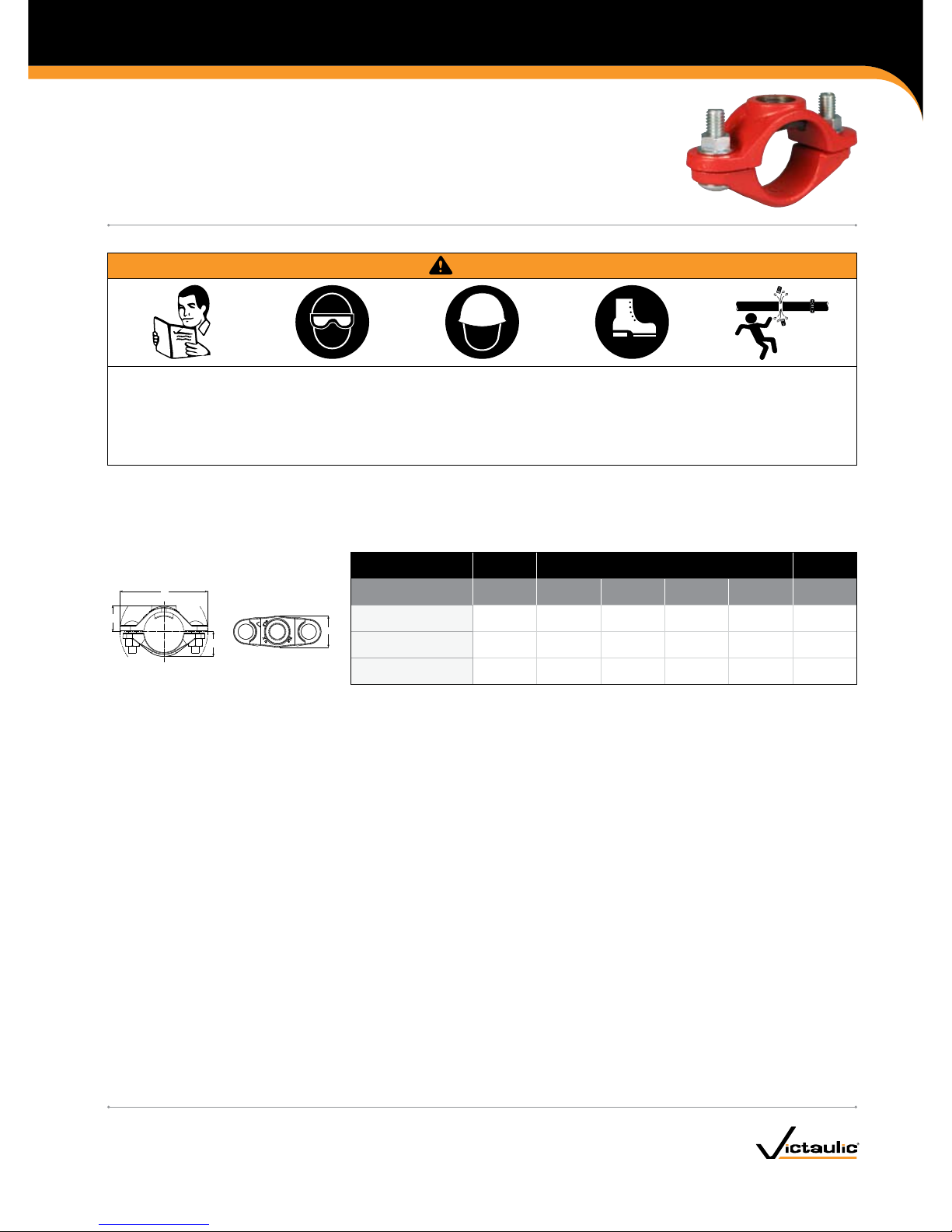
The Style 912 FireLock® Low-Profile Sprinkler Outlet-T is designed for direct connection of sprinkler heads and is FM Approved up to
300 psi/2068 kPa and VdS and LPCB Approved up to 16 Bar/232 psi at ambient temperatures that are typical for fire protection systems.
PRODUCT DATA
W
Z
V
Y
Nominal Size
inches/Actual mm
Hole
Diameter
Approximate
Weight Each
Run x Branch FPT†
+0.06/+1,5
–0.00/ –0,0 V W Y Z lbs/kg
1
x
½ ⁄ 1.00 0.90 3.72 1.50 0. 67
33.7 15. 0 24.0 25.4 22.9 94.6 38.1 0.30
1 ¼
x
½ ⁄ 1.17 1.10 4.12 1.5 0 0.74
42.4 15. 0 24. 0 29.8 27. 9 104 .7 38 .1 0.33
1 ½
x
½ ⁄ 1.2 9 1. 22 4.32 1. 50 0.76
48.3 15. 0 24. 0 32 .8 31.0 10 9.8 3 8.1 0.34
† Style 912 Low-Profile Sprinkler Outlet-T products are designed with female threads to ISO 7-Rp ½
(Rp ½ BSPP per BS21) and can accommodate only male sprinkler threads.
FOR SPRIN KLER USE ON LY. DO NOT USE A S A BRAN CH OUTLET.
WARNING
Read and understand all instructions before attempting to install any Victaulic piping products.•
Wear safety glasses, hardhat, and foot protection.•
Depressurize and drain the piping system before attempting to install, remove, adjust, or maintain any Victaulic piping products.•
Failure to follow these instructions could result in serious personal injury and/or property damage.
Page 2
I-912_2
FireLock® Low-Profile Sprinkler Outlet-T
STYLE 912
I-912
INSTALLATION INSTRUCTIONS
www.victaulic.com
VICTAULIC IS A REGISTERED TRADEMARK OF VICTAULIC COMPANY. © 2008 VICTAULIC COMPANY. ALL RIGHTS RESERVED. PRINTED IN THE USA.
REV_ A
PIPE PREPARATION
NOTICE
Victaulic hole cutting tools are recommended for proper hole •
preparation.
1. Cut a ⁄ -inch/24.0-mm hole on the centerline of the pipe.
¼ inch/6 mm
Exaggerated for cl arity
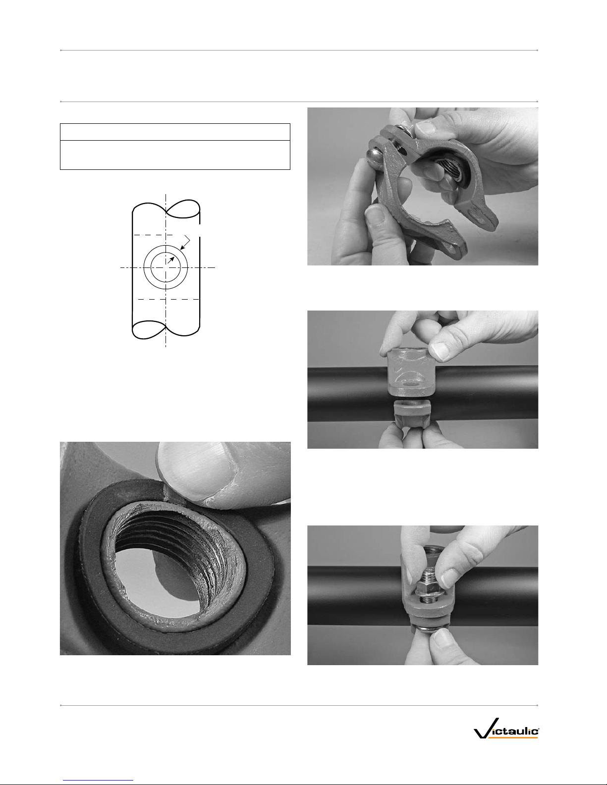
2. Ensure that a ¼-inch/6-mm area around the hole is clean, smooth,
and free from indentations and/or projections that could affect
gasket sealing (refer to the sketch above). Remove any burrs and
sharp or rough edges from the hole that might affect assembly,
proper seating of the locating collar, flow from the outlet, or gasket
seating.
INSTALLATION
1. Make sure the gasket is seated fully in the gasket pocket. DO NOT
LUBRICATE THE GASKET.
2. Remove the flange nut and bolt from one side of the Style 912
assembly. Thread the remaining flange nut loosely onto the bolt
(flange nut should be flush with end of bolt) to allow for the
“swing-over” feature.
3. Install the outlet housing onto the pipe by centering the locating
collar in the hole. To check for proper engagement, slide the outlet
housing back and forth while pushing down. A properly positioned
outlet housing can be moved only a small amount in any direction.
3a. Rotate the lower housing around the pipe, while holding the outlet
housing in place to make sure the locating collar remains seated
properly in the hole.
4. Insert the other track bolt into the lower housing and outlet
housing. Thread the flange nut onto the bolt finger-tight. Make sure
the track heads of the bolts seat properly in the bolt holes.
Page 3

I-912_3
FireLock® Low-Profile Sprinkler Outlet-T
STYLE 912
I-912INSTALLATION INSTRUCTIONS
www.victaulic.com
VICTAULIC IS A REGISTERED TRADEMARK OF VICTAULIC COMPANY. © 2008 VICTAULIC COMPANY. ALL RIGHTS RESERVED. PRINTED IN THE USA.
REV_ A
5. Tighten the flange nuts evenly to an approximate torque value of
20 ft-lbs/27.1-N•m to ensure proper gasket compression. NOTE:
To avoid over-tightening the flange nuts, use a wrench with a
maximum length of 8 inches/200 mm. DO NOT over-tighten the
flange nuts.
The outlet housing, near the gasket, should not make metal-to -metal
contact with the pipe. In addition, a small bolt pad gap is expected
between the outlet housing and the lower housing, as shown above.
WARNING
DO NOT over-tighten the flange nuts. Over-tightening the •
flange nuts can over-compress the gasket and distort the outlet
housing and lower housing. Over-tightening does not enhance
product performance.
Failure to follow this instruction could cause product failure,
resulting in serious personal injury and/or property damage.
Page 4

I-912
FireLock® Low-Profile Sprinkler Outlet-T
STYLE 912
I-912INSTALLATION INSTRUCTIONS
For complete contact information, visit w ww.victaulic.com
I-912 5372 REV A Z000912000 UPDATED 11/2008
VICTAULIC IS A REGISTERED TRADEMARK OF VICTAULIC COMPANY. © 2008 VICTAULIC COMPANY. ALL RIGHTS RESERVED. PRINTED IN THE USA.
WCAS-7HHHTM
 Loading...