

Victaulic 795 Series, 906 Series, I-795, I-906 Installation And Maintenance Instructions Manual
Page 1
WARNING
• Read and understand all instructions before attempting to install, remove, adjust, or maintain any Victaulic piping products.
• Depressurize and drain the piping system before attempting to install, remove, adjust, or maintain any Victaulic piping products.
• Wear safety glasses, hardhat, foot protection, and hearing protection.
Failure to follow instructions and warnings could cause system failure, resulting in death or serious personal injury and property damage.
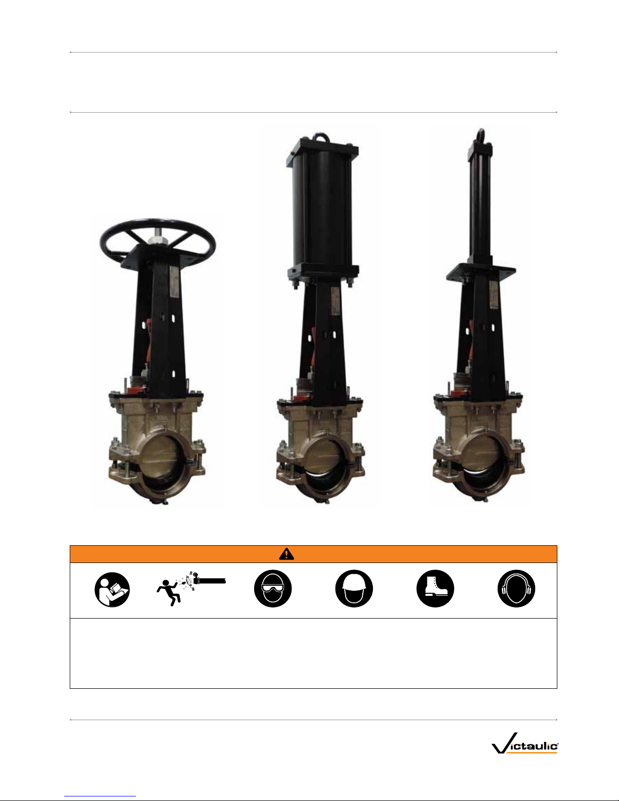
HANDWHEEL OPERATOR PNEU MATI C OP ERAT OR
HYDRAULIC OPERATOR
I-795/9 06
REV_D
I-795/906INSTALLATION AND MAINTENANCE INSTRUCTIONS
Series 795 and 906 Installation-Ready™ Knife Gate Valves
Page 2

Page 3
I-795 / 906 / Installation-Ready™ Knife Gate Valve / Installation and Maintenance Instructions
TABLE OF CONTENTS
Hazard Identification ......................................3
Knife Gate Valve Components ...............................4
Handwheel Operator Components ............................5
Pneumatic Operator Components ............................5
Hydraulic Operator Components .............................6
Dimensions – With Handwheel Operator .......................7
Dimensions – With Bevel Gear Operator........................8
Dimensions – With Pneumatic Operator ........................9
Dimensions – With Hydraulic Operator ........................10
Dimensions – Seat Cartridge ...............................11
Important Information ....................................12
Recommended Spare Parts and Tools ........................12
Manual Operation .......................................12
Pneumatic Operation.....................................12
Hydraulic Operation......................................12
SECTION I
Installing the 795 Valve Into a Steel Piping System............... 14
Installing the 906 Valve Into an HDPE Piping System .............18
SECTION II
Maintenance ...........................................24
Packing Adjustment....................................24
Lubrication ..........................................24
Removing the Existing Seat Cartridge.........................24
Installing the Replacement Seat Cartridge .....................29
HAZARD IDENTIFICATION
Definitions for identifying the various hazard levels are
provided below. When you see this symbol, be alert to the
possibility of personal injury. Carefully read and fully
u nderstand the message that follows.
DANGER
• The use of the word “DANGER” identifies an immediate
hazard with a likelihood of death or serious personal injury
if instructions, including recommended precautions, are not
followed.
WARNING
• The use of the word “WARNING” identifies the presence
of hazards or unsafe practices that could result in death or
serious personal injury if instructions, including recommended
precautions, are not followed.
CAUTION
• The use of the word “CAUTION” identifies possible hazards or
unsafe practices that could result in personal injury and product
or property damage if instructions, including recommended
precautions, are not followed.
NOTICE
• The use of the word “NOTICE” identifies special instructions
that are important but not related to hazards.
I-795/9 06_ 3
REV_D
Page 4
I-795 / 906 / Installation-Ready™ Knife Gate Valve / Installation and Maintenance Instructions
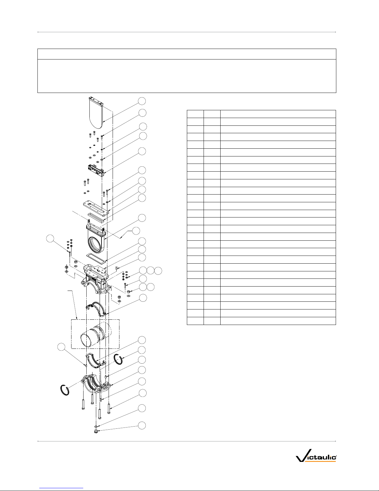
KNIFE GATE VALVE COMPONENTS
NOTICE
• Drawings and/or pictures in this manual may be exaggerated for clarity.
• Dimensions listed are for reference only. Refer to Victaulic submittal 08.25 or submittal 19.06 for complete dimensional information.
• The product, along with these installation and maintenance instructions, contains trademarks, copyrights, and/or patented features that are
the exclusive property of Victaulic.
BILL OF MATERIALS
Item Qt y. Description
1 1 Upper Body
2 1 Lower Body
3 2 Pipe Gasket
4 1 Seat Gasket
5 1 Seat
6 1 Knife Seal
7 1 Knife
8 1 Retaining Plate
9 1 Packing Gland
10 4 Full Thread Hex Bolt
†
11 4 Washer
†
12 4 Heavy Hex Nut
†
13 4 Washer
14 4 Helical Spring-Lock Washer
15 4 Hex Cap Screw
16 1 Dowel Pin
17 1 Dowel Pin
18 4 Hex Bolt
19 4 Helical Spring-Lock Washer
20 4 Hex Nut
21 1 O-Ring
22 1 Plug
23 8 Washer
24 2 Square Head Set Screw
‡
25 2 Spacer Bolt
26 2 Retainer *
27 2 Hex Cap Screw **
NOTES:
†
Items 10, 11, and 12 comprise the assembly hardware.
‡
Item 24 is used for 795 valve (carbon steel) only.
* Item 26 is used for 906 valve (HDPE) only.
** Item 27 is required when servicing the valve. Vic taulic offers a kit to replace
the entire seat cartridge. Refer to Section II in this manual for complete removal
and replacement instructions.
7
15
14
13
9
18
8
6
5
4
1
3
3
17
16
2
10
22
NIPPLES
SHOWN FOR
CLARITY
ONLY
21
12
11
20 19
23
24
24
23
25
25
27
26
I-795/9 06_ 4
REV_D
Page 5
I-795 / 906 / Installation-Ready™ Knife Gate Valve / Installation and Maintenance Instructions
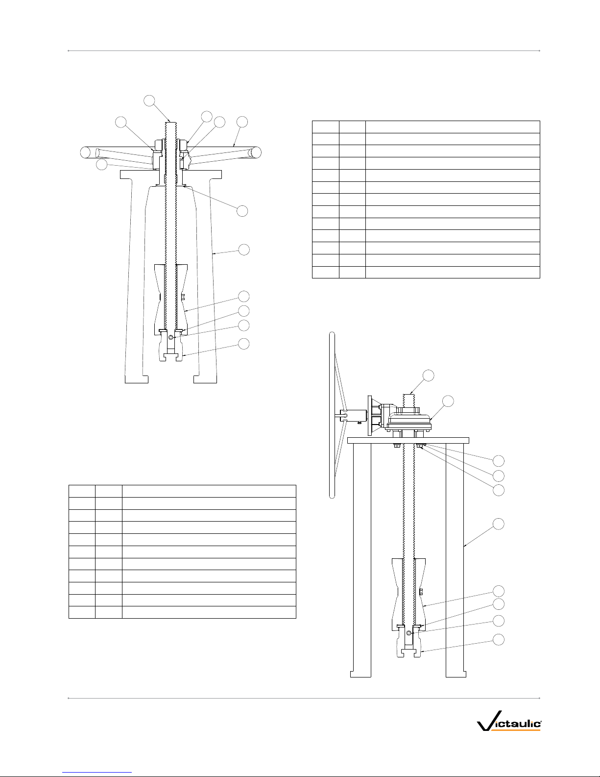
BILL OF MATERIALS
Item Qt y. Description
1 1 Yoke
2 1 Drive Nut
3 1 Spacer
4 1 Parallel Key
5 1 Handwheel
6 1 Washer
7 1 Stem
8 1 Hex Jam Nut
9 1 Gate Connector
10 1 Slotted Spring Pin
11 1 Stroke Limiter Assembly
12 1 Washer
1
5
8
7
2
4
6
3
9
10
11
12
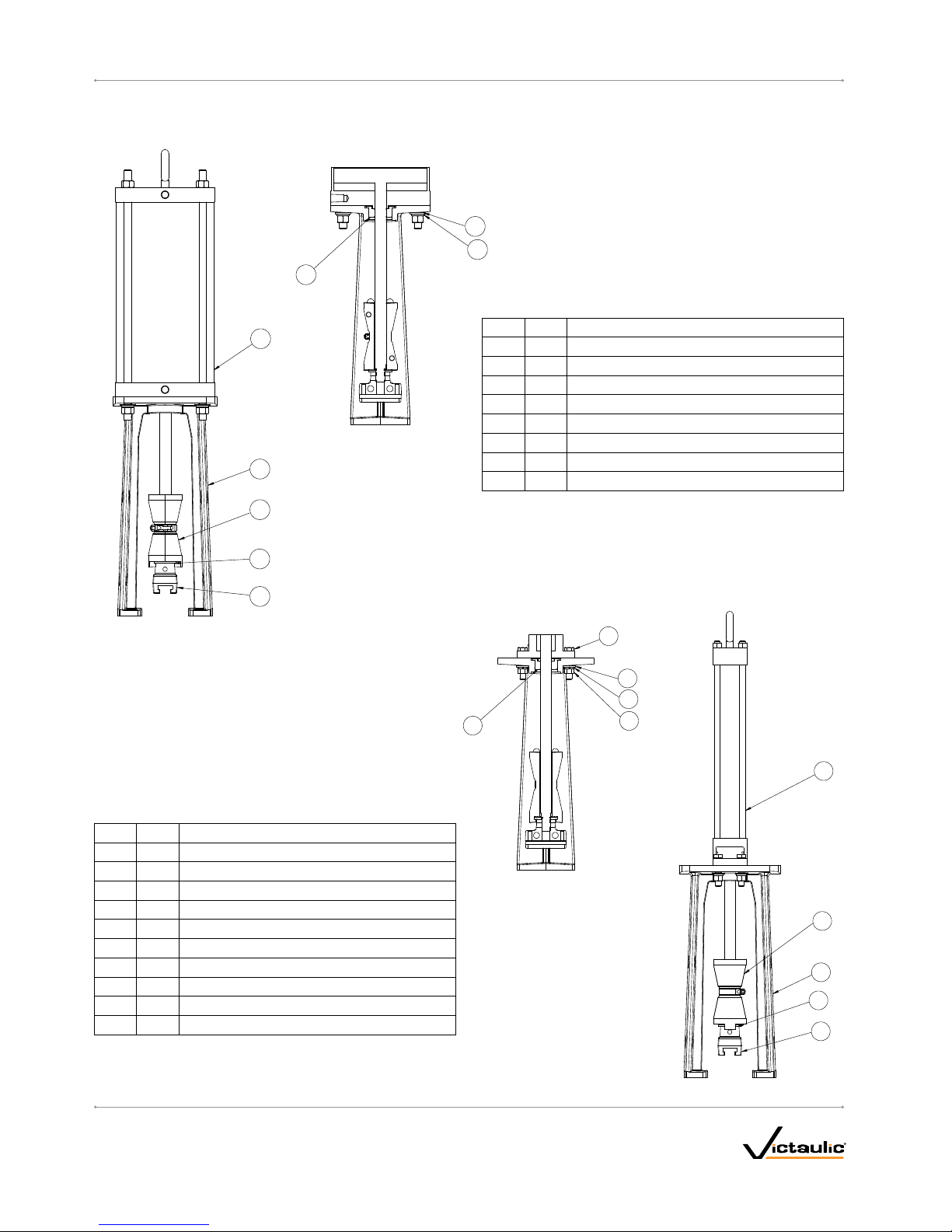
HANDWHEEL OPERATOR COMPONENTS (3 TO 8 INCH)
BEVEL GEAR COMPONENTS (10 TO 12 INCH)
27
28
29
30
21
23
24
25
22
26
BILL OF MATERIALS
Item Qt y. Description
21 1 Yoke
22 1 Gear Actuator
23 4 Washer
24 4 Helical Spring-Lock Washer
25 4 Hex Cap Screw
26 1 Stem
27 1 Gate Connector
28 1 Slotted Spring Pin
29 1 Stroke Limiter Assembly
30 1 Washer
I-795/9 06_ 5
REV_D
Page 6
I-795 / 906 / Installation-Ready™ Knife Gate Valve / Installation and Maintenance Instructions
3
4
2
5
1
6
7
8
22
25
27
23
24
28
21
26
29
30
BILL OF MATERIALS
Item Qt y. Description
21 1 Yoke
22 1 Hydraulic Cylinder
23 4 Washer
24 4 Helical Spring-Lock Washer
25 1 Bushing
26 1 Gate Connector
27 4 Hex Cap Screw
28 4 Hex Nut
29 1 Stroke Limiter Assembly
30 1 Washer
HYDRAULIC OPERATOR COMPONENTS
BILL OF MATERIALS
Item Qt y. Description
1 1 Yoke
2 1 Pneumatic Cylinder with Nuts
3 4 Washer
4 4 Helical Spring-Lock Washer
5 1 Bushing
6 1 Gate Connector
7 1 Stroke Limiter Assembly
8 1 Washer
PNEUMATIC OPERATOR COMPONENTS
I-795/9 06_ 6
REV_D
Page 7
I-795 / 906 / Installation-Ready™ Knife Gate Valve / Installation and Maintenance Instructions
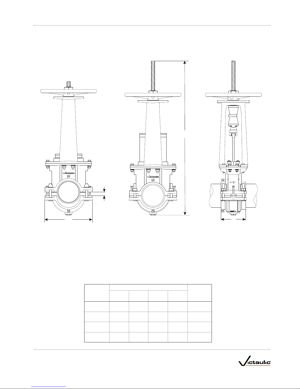
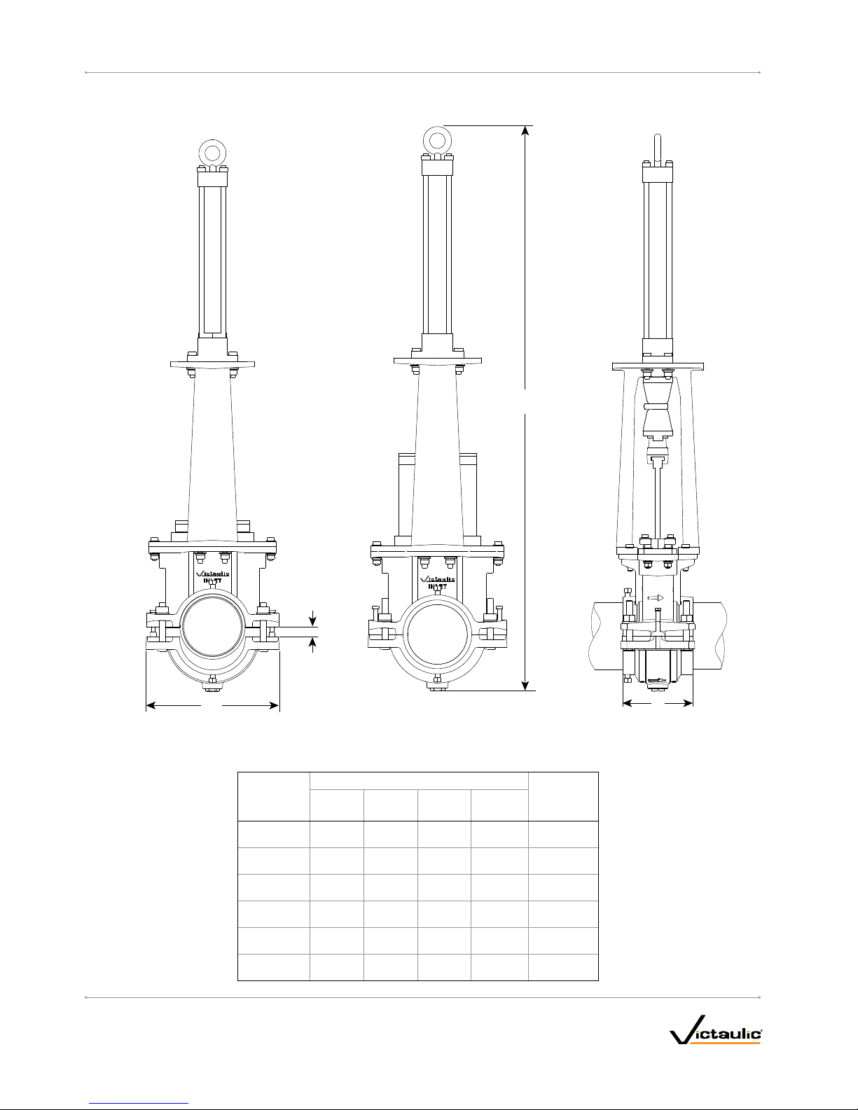
DIMENSIONS – WITH HANDWHEEL OPERATOR
VALVE CLOSED
NOT INSTALLED
VALVE OPEN
INSTALLED
VALVE OPEN
INSTALLED
E
C
H
F
Nominal Size
in
DN
Dimensions – inches/millimeters
Weight
lbs
kg
C E F H
3 0.88 10.25 6.75 32.25 113 .0 0
DN80 22.4 260.4 171. 5 819. 2 51.3
4 0.88 11. 25 6.75 34.75 122 .00
DN10 0 22.4 285.8 171. 5 882.7 55. 3
6 1.13 13.75 7. 00 43.75 166 .00
DN150 28.7 349.3 17 7.8 1111. 3 75.3
8 1.63 15. 50 7.00 53.25 23 7.0 0
DN200 41.4 393.7 17 7.8 1352. 6 107. 5
I-795/906_7
REV_D
Page 8
I-795 / 906 / Installation-Ready™ Knife Gate Valve / Installation and Maintenance Instructions
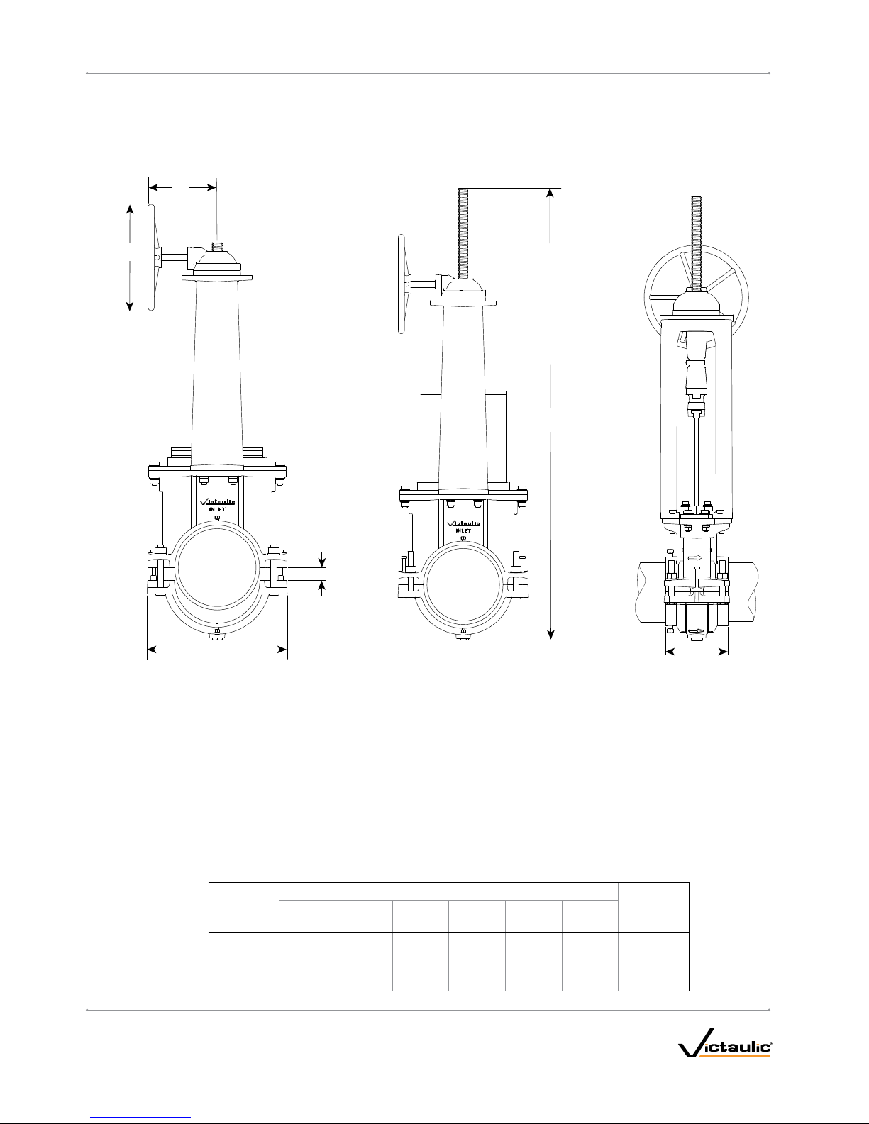
DIMENSIONS – WITH BEVEL GEAR OPERATOR
VALVE CLOSED
NOT INSTALLED
VALVE OPEN
INSTALLED
VALVE OPEN
INSTALLED
E
C
H
F
B
J
Nominal Size
in
DN
Dimensions – inches/millimeters
Weight
lbs
kg
B C E F H J
10 11. 22 1.75 19.0 0 7. 50 68.50 16.00 465.00
DN250 284.9 44.5 482.6 19 0.5 173 9. 9 406.4 210.9
12 11.22 2.00 21.00 7. 50 73.00 16.0 0 497.00
DN300 284.9 50.8 533.4 190 .5 1854. 2 406.4 225.4
I-795/9 06_ 8
REV_D
Page 9
I-795 / 906 / Installation-Ready™ Knife Gate Valve / Installation and Maintenance Instructions
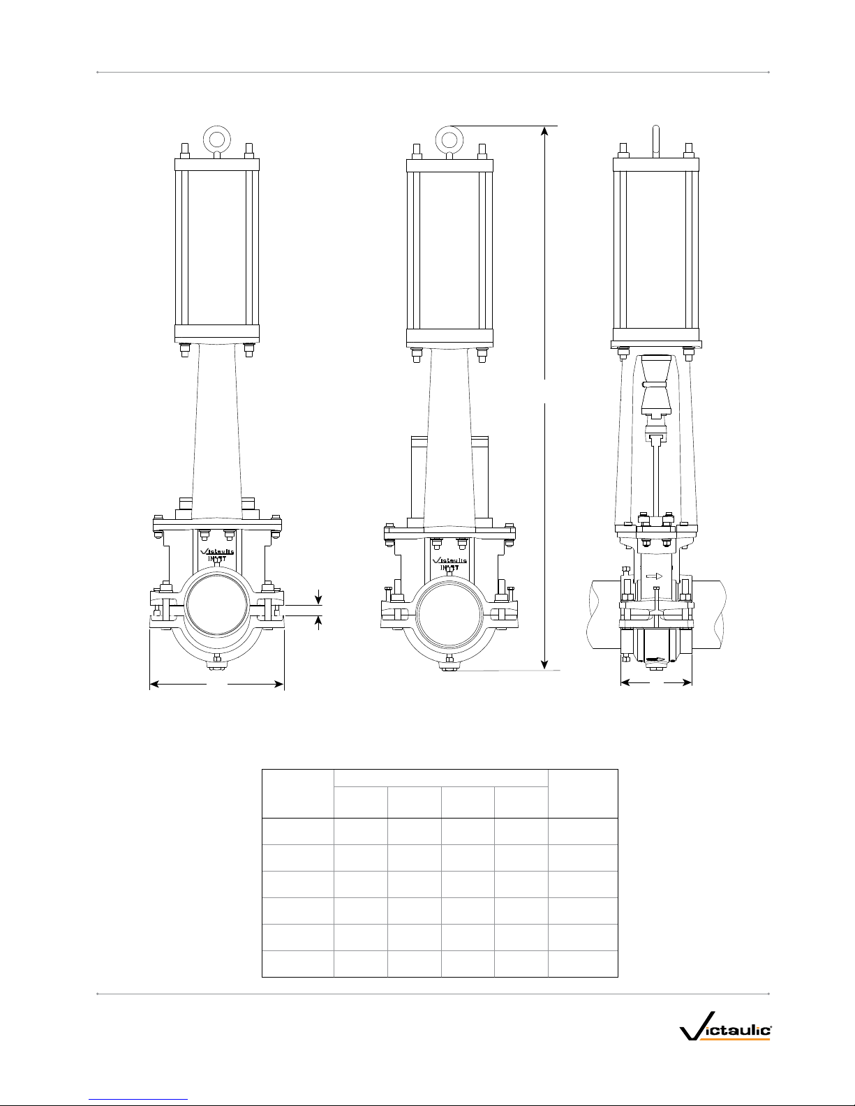
DIMENSIONS – WITH PNEUMATIC OPERATOR
VALVE CLOSED
NOT INSTALLED
VALVE OPEN
INSTALLED
VALVE OPEN
INSTALLED
H
C
E
F
Nominal Size
in
DN
Dimensions – inches/millimeters
Weight
lbs
kg
C E F H
3 0.88 10.25 6.75 42.0 0 126 .00
DN80 22.4 260.4 171. 5 106 6. 8 5 7.2
4 0.88 11. 25 6.75 44.50 133 .00
DN10 0 22.4 285.8 171. 5 1130.3 60.3
6 1.13 13 .75 7.0 0 53.75 215. 00
DN150 28.7 349.3 17 7.8 13 65.3 97. 5
8 1.63 15.50 7.0 0 55.75 348.00
DN200 41.4 393.7 177. 8 1416 .1 15 7.9
10 1.75 19.0 0 7.50 79.50 550.00
DN250 44.5 482.6 19 0. 5 2 019.3 249.5
12 2.00 21. 00 7. 50 86.50 586.00
DN300 50.8 533.4 19 0. 5 2 19 7.1 265.8
I-795/906_9
REV_D
Page 10
I-795 / 906 / Installation-Ready™ Knife Gate Valve / Installation and Maintenance Instructions
DIMENSIONS – WITH HYDRAULIC OPERATOR
VALVE CLOSED
NOT INSTALLED
VALVE OPEN
INSTALLED
VALVE OPEN
INSTALLED
H
C
E
F
Nominal Size
in
DN
Dimensions – inches/millimeters
Weight
lbs
kg
C E F H
3 0.88 10.25 6.75 43.88 115 .0 0
DN80 22.4 260.4 171. 5 111 4 . 6 52.2
4 0.88 11. 2 5 6.75 46.50 125. 00
DN10 0 22.4 285.8 171. 5 1181 .1 56.7
6 1.13 13 .75 7.0 0 55.00 17 2.0 0
DN150 28.7 349.3 17 7.8 13 97.0 78.0
8 1.63 15.50 7.0 0 66.50 259.00
DN200 41.4 393.7 177. 8 16 89.1 117. 5
10 1. 75 19 .0 0 7. 50 80.25 462.00
DN250 44.5 482.6 190. 5 2038.4 209.6
12 2.00 21. 00 7. 50 89.50 525.00
DN300 50.8 533.4 19 0. 5 2273.3 23 8.1
I-795/9 06_10
REV_D
Page 11

I-795 / 906 / Installation-Ready™ Knife Gate Valve / Installation and Maintenance Instructions
DIMENSIONS – SEAT CARTRIDGE
E
H
F
Nominal Size
in
DN
Dimensions – inches/millimeters
Weight
lbs
kg
E F H
3 9.88 3.88 10.8 8 16.30
DN80 2 51.0 98.6 276 .4 7.4
4 10.75 3.88 12 .13 19.7 0
DN10 0 273.1 98.6 308.1 8.9
6 13.0 0 3.88 15 .00 28.90
DN150 330.2 98.6 381.0 13.1
8 15.5 0 3.88 18. 25 40.70
DN200 39 7.3 98.6 463.6 18. 5
10 19. 00 5.00 23.00 82.0 0
DN250 482.6 127. 0 584.2 37. 2
12 20.63 5.00 25.50 10 0.60
DN300 524.0 127. 0 6 47. 7 45.6
I-795/ 9 06_ 11
REV_D
Page 12

I-795 / 906 / Installation-Ready™ Knife Gate Valve / Installation and Maintenance Instructions
IMPORTANT INFORMATION
• Series 795 Installation-Ready™ Knife Gate Valves are designed
for installation with grooved- end carbon steel or stainless steel
NPS pipe. For other pipe sizes and materials, contact Victaulic.
Welding of pipe ends to the valve is not permitted. Refer to the
Victaulic I-100 Field Installation Handbook for pipe preparation
requirements. The I-100 can be downloaded at victaulic.com.
• Series 906 Installation-Ready™ Knife Gate Valves are designed for
installation with plain-end HDPE pipe. Refer to the Victaulic I-900
Field Installation Handbook for pipe preparation requirements. The
I-900 can be downloaded at victaulic.com.
• Installation-Ready
™
Knife Gate Valves are rated for a maximum
working pressure of 150 psi/10 Bar.
• Installation-Ready
™
Knife Gate Valves are not intended for throttling
service. These valves are designed for shutoff applications only.
• Installation-Ready™ Knife Gate Valves are not intended for use in
air services.
• Installation-Ready™ Knife Gate Valves can be installed in any
orientation. NOTE: Additional supports shall be considered when
a 795 valve is installed horizontally, especially when a pneumatic,
electric, or hydraulic actuator is used. The 906 valve must be fully
supported in all installations.
• Installation-Ready
™
Knife Gate Valves and connecting piping must
be supported properly to prevent the joints from being subjected to
bending loads, shear loads, or any other external loads.
• DO NOT use Installation-Ready
™
Knife Gate Valves as a jack for
pipe alignment or support.
• DO NOT climb on or stand on Installation-Ready™ Knife Gate
Valves or other piping system components.
RECOMMENDED SPARE PARTS AND TOOLS
CAUTION
• Ensure that all spare seals and gaskets are compatible with the
line temperature and media.
Failure to follow this instruction will cause gasket degradation,
resulting in joint leakage and property damage.
• Spare Seat Cartridge
• Ratchet Wrenches
• Crescent Wrenches
• Pipe Wrenches
• Victaulic Lubricant or Silicone Lubricant
• Water-Stabilized Calcium Grease Containing Graphite and
Molybdenum Disulfide
• Anti-Seize Compound
MANUAL OPERATION
For Installation-Ready™ Knife Gate Valves installed with a handwheel operator, the following table contains the approximate number of complete
rotations required during standard operation (i.e. going from fully closed to fully open) or during maintenance to remove the seat cartridge.
Valve Size
inches
mm
Thrust Load
lbs
N
Approximate
Number of
Handwheel
Rotations
for Standard
Operation
Approximate
Number of
Handwheel
Rotations for
Maintenance
Maximum
Torq ue
Required
ft-lbs
N•m
Rim Pull
Effort
lb
N
3 150 0
20 45
11 16
80 6672 14 70
4 2100
25 55
15 22
100 9341 20 99
6 3000
35 70
22 33
150 13,344 29 145
8 4600
45 90
33 49
200 20,461 44 217
10* 7000
44 88
72 43
250 31,136 98 189
12* 7200
52 100
73 43
300 32,026 99 192
* These sizes come standard with a bevel gear operator.
PNEUMATIC OPERATION
Pneumatic cylinders are designed to be operated within 80–150 psi/6 –10 Bar air pressure. Contact Victaulic if your system air pressure is less than
80 psi/6 Bar. Additional information will be required to determine appropriate specifications for your system.
HYDRAULIC OPERATION
Hydraulic cylinders are designed to be operated within 1500–3000 psi/103–207 Bar hydraulic pressure. Contact Victaulic if your system hydraulic
pressure is less than 1500 psi/103 Bar. Additional information will be required to determine appropriate specifications for your system.
I-795/9 06_12
REV_D
Page 13

SECTION I
• Installing the 795 Valve
Into a Steel Piping System
• Installing the 906 Valve
Into an HDPE Piping
System
I-795_13
REV_D
Page 14

I-795 / 906 / Installation-Ready™ Knife Gate Valve / Installation and Maintenance Instructions
INSTALLING THE 795 VALVE INTO A STEEL
PIPING SYSTEM
WARNING
• This valve is intended for use on grooved-end carbon steel or
stainless steel NPS pipe and is NOT to be used on HDPE pipe.
Failure to follow this instruction could result in personal injury,
joint leakage, and property damage, and could void the product
warranty.
1. DO NOT REMOVE OR ADJUST THE ASSEMBLY HARDWARE:
Series 795 Installation-Ready™ Knife Gate Valves are designed so
that the installer does not need to remove the assembly hardware for
installation. This design facilitates installation by allowing the installer to
directly insert a grooved pipe end into each opening of the valve.
2. INSPECT PIPE ENDS: The outside surface of the pipe, between the
groove and the pipe end, must be smooth and free from indentations,
projections, weld seams, and roll marks to ensure a leak-tight seal. All
oil, grease, loose paint, dirt, and cut ting particles must be removed. The
pipe OD, groove dimensions, and maximum allowable flare diameter
must be within the tolerances published in current Victaulic grooving
specifications. NOTE: Maximum allowable pipe ovality shall comply
with the requirements of ASTM A-999 and API 5L. Greater variations
between the major and minor pipe diameters will result in difficult
assembly and potential joint leakage.
3. INSPECT PIPE GASKETS: Check the pipe gaskets to ensure that
they are suitable for the intended service. The color code identifies the
gasket grade. Refer to Victaulic publication 05.01 in the G-100 General
Catalog for the color code chart.
CAUTION
• A compatible lubricant must be used to prevent the pipe gaskets
from pinching /tearing during installation.
• Pipe gaskets are designed for one-time use only. DO NOT
attempt to reuse pipe gaskets that have been placed in service.
Failure to follow these instructions will cause gasket degradation,
resulting in joint leakage and property damage.
Lubricate
4. LUBRICATE PIPE GASKETS: Apply a thin coat of Victaulic Lubricant
or silicone lubricant only to the sealing lips of the pipe gaskets’ interior.
NOTE: The exterior surface of the pipe gaskets is supplied with a
factory-applied lubricant.
NOTICE
• It is not necessary to remove the pipe gaskets from the valve to
apply additional lubricant to the exterior surface.
TABLE 1: LUBRICANT COMPATIBILITY
Lubricant
Compatibility
with Grade “T”
Nitrile Gaskets
Compatibility
with Grade “E”
EPDM Gaskets
Victaulic Lubricant,
Soap-Based Solutions, Glycerin,
Silicone Oil, or Silicone Release Agent
Good Good
Corn Oil, Soybean Oil,
Hydrocarbon-Based Oils,
or Petroleum- Based Greases
Good
Not
Recommended
WARNING
• Keep hands away from the pipe ends and
the openings of the valve when attempting to
insert grooved pipe ends into the valve.
Failure to follow this instruction could result in
serious personal injury.
I-795/9 06_14
REV_D
Page 15

I-795 / 906 / Installation-Ready™ Knife Gate Valve / Installation and Maintenance Instructions
5a. ASSEMBLE JOINT: Assemble the joint by inserting a grooved pipe
end into each opening of the valve.
Inspect
5b. INSPECT KEYS: Each grooved pipe end must be inserted into
the valve until contact with the seat occurs, as shown above. This will
ensure that the valve body’s keys align with the grooves in the pipe
ends.
5c. REMOVE ONLY THE SPACER BOLTS: There is one spacer bolt
on each bolt pad to maintain spacing between the bolt pads during
shipping and assembly. After inserting pipe, remove only the spacer
bolts and the attached warning tags before tightening the four nuts in
step 6.
CAUTION
• Spacer bolts are designed to keep the valve’s housings at the
proper spacing during installation of the pipe ends.
• These spacer bolts must be removed prior to tightening the hex
nuts to bring the bolt pads into metal-to-metal contact. The
bolts will prevent proper tightening of the valve housings.
Failure to follow these instructions will cause damage to the valve
components. This may result in joint leakage or property damage,
and could void the product warranty.
NOTE: Do NOT discard the spacer bolts. Reinstall the spacer bolts
to finger-tight after valve installation is complete. If the valve must be
removed from the system, the spacer bolts will be necessary to separate
housings and maintain spacing (dimension "C", as defined in the
dimension tables found on pages 7–10) between the bolt pads during
storage, shipping, and reinstallation.
6. TIGHTEN NUTS: Tighten the hex nuts evenly by alternating sides
in a crossing pattern (as shown in the sequence above) until metal-tometal contact occurs at the bolt pads. Ensure that the valve body’s keys
engage the grooves completely during tightening.
NOTE: It is important to tighten the hex nuts evenly by alternating sides
to prevent pinching of the pipe gaskets. An impact wrench or standard
socket wrench with a deep-well socket can be used to bring the bolt
pads into metal-to-metal contact. Refer to the “Series 795 Helpful
Information” and “Impact Wrench Usage Guidelines” sections.
WARNING
• Visual inspection of each joint is critical.
• Improperly assembled joints must be corrected before the
system is placed into service.
Failure to follow these instructions could cause joint failure,
resulting in serious personal injury and/or property damage.
I-795/9 06_15
REV_D
Page 16

I-795 / 906 / Installation-Ready™ Knife Gate Valve / Installation and Maintenance Instructions
GOOD
BAD
7. INSPECT PADS: Visually inspect the bolt pads at each joint to ensure
that metal-to-metal contact is achieved across the entire bolt pad
section.
8. TIGHTEN 360° POSITIONING BOLTS: Tighten the two 360°
positioning bolts evenly by alternating sides until they reach a nominal
torque of 40 ft-lbs/54.23 N•m.
I-795/9 06_16
REV_D
Page 17

I-795 / 906 / Installation-Ready™ Knife Gate Valve / Installation and Maintenance Instructions
NOTICE
A locking pin is provided to assist with Lockout/Tagout procedures
during installation and maintenance. Ensure that the pin is
removed before attempting to place the valve into service.
IMPACT WRENCH USAGE GUIDELINES
WARNING
• It is important to tighten the nuts evenly by alternating sides
until metal-to-metal c ontact occurs at the bolt pads.
• DO NOT continue to tighten the nuts after the visual installation
guidelines for the product are achieved.
Failure to follow these instructions could cause gasket pinching and
product damage, resulting in joint failure, serious personal injury,
and property damage.
Due to the speed of assembly when using an impact wrench, the
installer should take extra care to ensure that nuts are tightened evenly
by alternating sides until proper assembly is complete. Always refer to
the specific product installation instructions for complete installation
requirements.
Impact wrenches do not provide the installer with direct “wrench feel” or
torque to judge nut tightness. Since some impact wrenches are capable
of high output, it is important to develop a familiarity with the impact
wrench to avoid damaging or fracturing the bolts or the bolt pads during
installation. DO NOT continue to tighten the nuts after the visual
installation guidelines are achieved.
If the battery is drained or if the impact wrench is under-powered, a new
impact wrench or a new battery pack must be used to ensure that the
visual installation guidelines for the product are achieved.
Perform trial assemblies with the impact wrench and check the
assemblies with socket or torque wrenches to help determine the
capability of the impact wrench. Using the same method, periodically
check additional nuts throughout the system installation.
For safe and proper use of impact wrenches, always refer to the impact
wrench manufacturer’s operating instructions. In addition, verify that
proper impact grade sockets are being used for product installation.
WARNING
Failure to follow instructions for tightening product hardware could
result in:
• Bolt fractures
• Damaged or broken bolt pads or product fractures
• Joint leakage
Series 795 Helpful Information
Valve
Size
Spacer
Bolt Size
Spacer Bolt
Socket
inches/mm
Coupling
Nut
Size
Coupling Nut
Deep-Well Socket
inches/mm
3
⁄" - 16 UNC x 2"
⁄
½" - 13 Heavy Hex
⁄
14 19
4
⁄" - 16 UNC x 2"
⁄
½" - 13 Heavy Hex
⁄
14 19
6
⁄" - 16 UNC x 3"
⁄
⁄" - 11 Heavy Hex
1 ⁄
14 27
8
⁄" - 16 UNC x 3"
⁄
⁄" - 11 Heavy Hex
1 ⁄
14 27
10
½" - 13 UNC x 3.5"
¾
⁄" - 9 Heavy Hex
1 ⁄
19 36
12
½" - 13 UNC x 3.5"
¾
⁄" - 9 Heavy Hex
1 ⁄
19 36
I-795/9 06_17
REV_D
Page 18

I-795 / 906 / Installation-Ready™ Knife Gate Valve / Installation and Maintenance Instructions
INSTALLING THE 906 VALVE INTO AN HDPE
PIPING SYSTEM
WARNING
• Wear gloves while handling valve. Retainer
teeth are sharp and may cause injury.
• This valve is intended for use on plain-end
HDPE pipe and is NOT to be used on steel
pipe.
Failure to follow these instructions could result
in personal injury, joint leakage, and property
damage, and could void the product warranty.
1a. DO NOT REMOVE OR ADJUST THE ASSEMBLY HARDWARE:
Series 906 Installation-Ready™ Knife Gate Valves are designed so
that the installer does not need to remove the assembly hardware for
installation. This design facilitates installation by allowing the installer to
directly insert a pipe end into each opening of the valve.
1b. REMOVE SLEEVE: Remove the cardboard sleeve from the valve
interior. NOTE: This cardboard sleeve will be used as a guide for
marking the pipe ends in step 4.
2. INSPECT PIPE ENDS: Ensure that the pipe ends are clean and free
from damage and scratches within 2 ½ inches/64 mm from the ends. All
oil, grease, dirt, and cutting particles must be removed. Failure to do so
will result in difficult assembly and potential joint leakage.
3. INSPECT PIPE GASKETS: Check the pipe gaskets to ensure that
they are suitable for the intended service. The color code identifies the
gasket grade. Refer to Victaulic publication 05.01 in the G-100 General
Catalog for the color code chart.
CAUTION
• A compatible lubricant must be used to prevent the pipe gaskets
from pinching /tearing during installation.
• Pipe gaskets are designed for one-time use only. DO NOT
attempt to reuse pipe gaskets.
Failure to follow these instructions will cause gasket degradation,
resulting in joint leakage and property damage.
4. MARK PIPE: Using the cardboard sleeve and a paint stick, mark
each HDPE pipe end around the full circumference:
• 1 7/8 inches/48 mm for 2–3-inch pipe sizes
• 2 ¼ inches/57 mm for 4–8-inch pipe sizes
This mark will be used for visual inspection to ensure that the HDPE
pipe is inserted properly in the valve. If a full circumferential mark
cannot be achieved, make at least four marks equally-spaced around
the circumference of each HDPE pipe end.
5. LUBRICATE PIPE END: Apply a thin coat of lubricant to the pipe
end from the end of the pipe to the paint mark made in step 4.
Lubricate each pipe end in accordance with the “Lubricant
Compatibility” table. Always consult with the pipe manufacturer for
lubricant compatibility requirements.
I-795/9 06_18
REV_D
Page 19

I-795 / 906 / Installation-Ready™ Knife Gate Valve / Installation and Maintenance Instructions
TABLE 1: LUBRICANT COMPATIBILITY
Lubricant
Compatibility
with Grade “T”
Nitrile Gaskets
Compatibility
with Grade “E”
EPDM Gaskets
Victaulic Lubricant,
Soap-Based Solutions, Glycerin,
Silicone Oil, or Silicone Release Agent
Good Good
Corn Oil, Soybean Oil,
Hydrocarbon-Based Oils,
or Petroleum- Based Greases
Good
Not
Recommended
WARNING
• Keep hands away from the pipe ends and the
openings of the valve when attempting to insert
pipe ends into the valve.
Failure to follow this instruction could result in
personal injury.
5a. ASSEMBLE JOINT: Assemble the joint by inserting the marked
HDPE pipe end into each opening of the valve. The HDPE pipe ends
must be inserted into the valve until (1) contact with the seat occurs
AND (2) the marks on the HDPE pipe ends meets the edge of the valve
body, as shown above.
Inspect
5b. INSPECT SEAT: Each pipe end must be inserted into the valve until
contact with the seat occurs, as shown above. A visual check is required
to ensure that the seat meets the pipe ends.
5c. REMOVE ONLY THE SPACER BOLTS: There is one spacer bolt on
each bolt pad to maintain spacing between the bolt pads during shipping
and assembly. After inserting pipe, remove only the spacer bolts and the
attached warning tags before tightening the four nuts in step 6.
CAUTION
• Spacer bolts are designed to keep the valve’s housings at the
proper spacing during installation of the pipe ends.
• These spacer bolts must be removed prior to tightening the hex
nuts to bring the bolt pads into metal-to-metal contact. The
bolts will prevent proper tightening of the valve housings.
Failure to follow these instructions will cause damage to the valve
components. This may result in joint leakage or property damage,
and could void the product warranty.
NOTE: Do NOT discard the spacer bolts. Reinstall the spacer bolts
to finger-tight after valve installation is complete. If the valve must be
removed from the system, the spacer bolts will be necessary to separate
housings and maintain spacing (dimension "C", as defined in the
dimension tables found on pages 7–10) between the bolt pads during
storage, shipping, and reinstallation.
I-795/9 06_19
REV_D
Page 20

I-795 / 906 / Installation-Ready™ Knife Gate Valve / Installation and Maintenance Instructions
6. TIGHTEN NUTS: Tighten the hex nuts evenly by alternating sides in a
crossing pattern (as shown in the sequence above) until metal-to-metal
contact occurs at the bolt pads.
NOTE: It is important to tighten the hex nuts evenly by alternating sides
to prevent pinching of the pipe gaskets. An impact wrench or standard
socket wrench with a deep-well socket can be used to bring the bolt
pads into metal-to-metal contact. Refer to the “Series 906 Helpful
Information” and “Impact Wrench Usage Guidelines” sections.
WARNING
• Visual inspection of each joint is critical.
• Improperly assembled joints must be corrected before the
system is placed into service.
Failure to follow these instructions could cause joint failure,
resulting in serious personal injury and/or property damage.
GOOD
BAD
7. INSPECT PADS: Visually inspect the bolt pads at each joint to ensure
that metal-to-metal contact is achieved across the entire bolt pad
section.
I-795/9 06_ 20
REV_D
Page 21

I-795 / 906 / Installation-Ready™ Knife Gate Valve / Installation and Maintenance Instructions
NOTICE
A locking pin is provided to assist with Lockout/Tagout procedures
during installation and maintenance. Ensure that the pin is
removed before attempting to place the valve into service.
IMPACT WRENCH USAGE GUIDELINES
WARNING
• It is important to tighten the nuts evenly by alternating sides
until metal-to-metal c ontact occurs at the bolt pads.
• DO NOT continue to tighten the nuts after the visual installation
guidelines for the product are achieved.
Failure to follow these instructions could cause gasket pinching and
product damage, resulting in joint failure, serious personal injury,
and property damage.
Due to the speed of assembly when using an impact wrench, the
installer should take extra care to ensure that nuts are tightened evenly
by alternating sides until proper assembly is complete. Always refer to
the specific product installation instructions for complete installation
requirements.
Impact wrenches do not provide the installer with direct “wrench feel” or
torque to judge nut tightness. Since some impact wrenches are capable
of high output, it is important to develop a familiarity with the impact
wrench to avoid damaging or fracturing the bolts or the bolt pads during
installation. DO NOT continue to tighten the nuts after the visual
installation guidelines are achieved.
If the battery is drained or if the impact wrench is under-powered, a new
impact wrench or a new battery pack must be used to ensure that the
visual installation guidelines for the product are achieved.
Perform trial assemblies with the impact wrench and check the
assemblies with socket or torque wrenches to help determine the
capability of the impact wrench. Using the same method, periodically
check additional nuts throughout the system installation.
For safe and proper use of impact wrenches, always refer to the impact
wrench manufacturer’s operating instructions. In addition, verify that
proper impact grade sockets are being used for product installation.
WARNING
Failure to follow instructions for tightening product hardware could
result in:
• Bolt fractures
• Damaged or broken bolt pads or product fractures
• Joint leakage
Series 906 Helpful Information
Valve
Size
Spacer
Bolt Size
Spacer Bolt
Socket
inches/mm
Coupling
Nut
Size
Coupling Nut
Deep-Well Socket
inches/mm
3
⁄" - 16 UNC x 2"
⁄
½" - 13 Heavy Hex
⁄
14 19
4
⁄" - 16 UNC x 2"
⁄
½" - 13 Heavy Hex
⁄
14 19
6
⁄" - 16 UNC x 3"
⁄
⁄" - 11 Heavy Hex
1 ⁄
14 27
8
⁄" - 16 UNC x 3"
⁄
⁄" - 11 Heavy Hex
1 ⁄
14 27
I-795/9 06_ 21
REV_D
Page 22

This page intentionally blank
Page 23

SECTION II
• Maintenance
• Removing the Seat Cartridge
• Installing the Seat Cartridge
Page 24

I-795 / 906 / Installation-Ready™ Knife Gate Valve / Installation and Maintenance Instructions
MAINTENANCE
Maintenance should be performed on the Installation-Ready™ Knife
Gate Valve on a regularly scheduled basis, as established by job site
requirements, or when leakage occurs.
PACKING ADJUSTMENT
1
3
4
2
If leakage occurs at the packing, tighten the hex cap screws evenly in
¼ turns by alternating sides (as shown in the sequence above) until
leakage stops. If leakage persists, perform the instructions that follow
to remove and replace the seat cartridge.
LUB RICATION
For handwheel, bevel gear, or
electrically operated valves,
Victaulic recommends greasing
the threaded stem and drive nut
on a quarterly basis, depending on
the number of cycles. If the valve
is cycled on a daily basis, increase
the frequency of lubricating the
threaded stem to ensure proper
handwheel operation.
Apply a water-stabilized calcium
grease containing graphite and
molybdenum disulfide (Mobil
Mobilux™ EP 1 or equivalent)
to the entire threaded stem and
drive nut. Operate the handwheel to raise and lower the threaded stem
to ensure that grease is distributed evenly. NOTE: If the valve is in a
critical shutoff service and cannot be cycled, insert the locking pin
(referenced on page 17) through the yoke (page 5, item 1) into the gate
connector (page 5, item 9). Disconnect the threaded stem (page 5, item
7) from the gate connector by removing the slotted spring pin (page 5,
item 10). Cycle the threaded stem independent of the gate connector,
then replace the slotted spring pin and remove the lockout bolt.
For pneumatically or hydraulically operated valves, refer to the actuator
manufacturer’s maintenance instructions.
REMOVING THE EXISTING SEAT CARTRIDGE
DANGER
• Depressurize and drain the piping
system completely before attempting
to remove the seat cartridge.
Failure to follow this instruction could
result in death or serious personal injury
and property damage.
WARNING
• Read and understand all instructions
before attempting to install, remove,
adjust, or maintain any Victaulic
piping products.
• Wear safety glasses, hardhat, foot
protection, and hearing protection.
Failure to follow instructions and warnings could cause system
failure, resulting in death or serious personal injury and property
damage.
1. DEPRESSURIZE AND DRAIN SYSTEM: Depressurize, drain, and
flush the piping system completely and return the knife to the fully
closed position before attempting to remove the seat cartridge.
Stroke
Limiter
2. REMOVE STROKE LIMITER: Remove the stroke limiter in order to
raise the stem completely.
Apply
grease
here
™ Mobilux is a trade mark of Ex xon Mobil Corp oration.
I-795/9 06_ 24
REV_D
Page 25

I-795 / 906 / Installation-Ready™ Knife Gate Valve / Installation and Maintenance Instructions
2a. Using a ⁄inch/11 mm deep-well socket wrench, remove the nut
on the T-bolt clamp and pull the clamp apart.
2b. Remove the T-bolt clamp and split the two halves of the stroke
limiter to remove.
Remove
3. REMOVE PLUG: Using a 1 ¼-inch/32 mm wrench (for the 3 to 8"
valves) or a 1 ½-inch/38 mm wrench (for the 10 to 12" valves), remove
the plug from the bottom of the valve body.
I-795/9 06_ 25
REV_D
Page 26

I-795 / 906 / Installation-Ready™ Knife Gate Valve / Installation and Maintenance Instructions
4. REMOVE AND RELOCATE GATE CONNECTOR SCREWS: Remove
the two hex cap screws from the gate connector. Relocate them through
the tab on each side of the seat and into the side of the knife, then
finger-tighten. This is necessary to attach the seat to the knife during
removal in later steps.
Valve
Size
Retaining Plate
Bolt Size
Retaining Plate
Socket Size
inches/mm
3–8"
⁄"
⁄-
inch/M16 Bo lt
¾-inch/M19 Nut
10 –12 "
¾"
1 ⁄-inch/M29 Bolt
1
⁄-inch/M29 Nut
5. REMOVE RETAINING BOLTS: Remove the four hex cap bolts and
nuts from the retaining plate, as shown above.
NOTE: Do NOT remove the packing screws. Doing so will damage the
seat.
I-795/9 06_ 26
REV_D
Page 27

I-795 / 906 / Installation-Ready™ Knife Gate Valve / Installation and Maintenance Instructions
6a. OPEN VALVE: For handwheel operated valves, operate the
handwheel in the “open” direction (counterclockwise) to draw the seat
out from the valve body.
CAUTION
• Support the seat cartridge during actuation to prevent lateral
movement. Though the valve is operable in any configuration,
angled placement may allow an unsupported seat cartridge to
slide out of the gate connector prematurely.
Failure to follow this instruction could result in personal injury or
property damage.
6b. For pneumatically or hydraulically operated valves, actuate the valve
open to draw the seat out from the valve body.
CAUTION
• Support the seat cartridge during actuation to prevent lateral
movement. Though the valve is operable in any orientation,
angled placement may allow an unsupported seat cartridge to
slide out of the gate connector prematurely.
Failure to follow this instruction could result in personal injury or
property damage.
I-795/9 06_ 27
REV_D
Page 28

I-795 / 906 / Installation-Ready™ Knife Gate Valve / Installation and Maintenance Instructions
WARNING
• Keep hands away from the edges of the knife
seat while lifting it from the valve body.
Failure to follow this instruction could result in
personal injury.
7. REMOVE CARTRIDGE: When the seat has cleared the opening of
the valve body, slide the seat cartridge out from the slot in the gate
connector, as shown above. For clearance measurements, reference the
E dimension in the table on page 11.
NOTE: When removing the seat cartridge, be prepared to suppor t
its weight with both hands. Refer to the table on page 11 for specific
weights before attempting to remove the seat cartridge. Larger sizes
may require the use of mechanical lifting equipment.
Sealing Faces
8. CLEAN VALVE: Ensure that the seat cavit y and drain plug are free
from debris by flushing the cavity with water. Wipe clean the sealing
faces with a rag or brush.
Inspect the cavity to ensure that par ticles have been removed. All
foreign matter should be cleared away before replacing the seat
cartridge.
NOTICE
• Victaulic recommends having a spare replacement seat cartridge
available to prevent maintenance delays.
I-795/9 06_ 28
REV_D
Page 29

I-795 / 906 / Installation-Ready™ Knife Gate Valve / Installation and Maintenance Instructions
INSTALLING THE REPLACEMENT SEAT
CARTRIDGE
Tab
Slot
1a. PREPARE CARTRIDGE SURFACES: Apply a thin coat of Victaulic
Lubricant or silicone lubricant to all exterior surfaces of the new seat
cartridge. NOTE: The seat contains a tab that must be installed facing
the slot in the valve body, as shown above.
1b. Add a thin coat of anti-seize compound to the top of the knife, as
shown to the right, to aid with installation and with future removal of the
cartridge.
Apply
anti-seize
compound
2. INSERT CARTRIDGE: Slide the replacement seat cartridge into the
slot in the gate connector, as shown above.
I-795/9 06_ 29
REV_D
Page 30

I-795 / 906 / Installation-Ready™ Knife Gate Valve / Installation and Maintenance Instructions
3a. CLOSE VALVE: For handwheel operated valves, operate the
handwheel slowly in the “closed” direction (clockwise) to bring the
seat toward the valve body. Ensure that the tab of the seat is facing the
slot in the valve body, as shown in step 1. To prevent damage to the
surfaces of the seat, do not attempt to operate the handwheel at an
increased rate, or by using a drill or impact gun.
3b. For pneumatically and hydraulically operated valves, actuate the
valve closed to bring the seat toward the valve body.
WARNING
• Keep hands away from the edges of the knife
seat while replacing it into the valve body.
• Keep hands away from the seat cartridge and
yoke while actuating the valve.
Failure to follow this instruction could result in
personal injury.
4. REPLACE RETAINING BOLTS: When the retaining plate is
1 inch/25 mm or less from the valve body, insert the four hex cap bolts
and flat washers through the retaining plate and into the valve body, as
shown ab ove.
5. TIGHTEN RETAINING BOLTS: Tighten the four hex cap bolts evenly
by alternating sides (as shown in the sequence above) until the lock
washers are fully compressed. There should be metal-to-metal contact
between the plate and the housing.
I-795/9 06_ 30
REV_D
Page 31

I-795 / 906 / Installation-Ready™ Knife Gate Valve / Installation and Maintenance Instructions
6. REMOVE AND RELOCATE GATE CONNECTOR SCREWS: Remove
the two hex cap screws from the knife and relocate them to the gate
connector, as shown above. Ensure that the hex cap screw is threaded
down so that the head is below the washer (page 5, item 12).
7. REPLACE PLUG: Replace the plug in the bottom of the valve body,
tightening the plug as directed in the chart below.
Valve Size
Plug Installation Torque
Lower Nut +/- 20%
3–8"
60 ft-lbs
81.3 N• m
10 –12"
100 ft-lbs
135.6 N•m
Stroke
Limiter
8. REPLACE STROKE LIMITER: Replace the stroke limiter on the stem
by reversing the procedure for removal. Do not tighten the T-bolt clamp
past 75 in-lbs.
CAUTION
• DO NOT attempt to place the valve back in service without
replacing the stroke limiter.
Failure to follow these instructions will cause damage to the valve
components. This may result in joint leakage or property damage,
and could void the product warranty.
9. INSPECT GAP: Operate the handwheel (or the pneumatic or hydraulic
operator) to raise the knife out of the valve body. Ensure that the gap on
both sides of the knife is equal, as shown above. The hex cap screws of
the packing gland can be adjusted, if necessary, to achieve an equal gap
on both sides of the knife. Refer to the "Packing Adjustment" section on
page 24 to review adjusting the hex cap screws.
I-795/9 06_ 31
REV_D
Page 32

I-795/906INSTALLATION AND MAINTENANCE INSTRUCTIONS
Series 795 and 906 Installation-Ready™ Knife Gate Valves
For complete contact information, visit victaulic.com
I-795/906 8413 REV D UPDATED 6/2017 Z000795000
VICTAULIC AND INSTALLATION-READY ARE REGISTERED TRADEMARKS OR TRADEMARKS OF VICTAULIC COMPANY AND/OR ITS AFFILIATED
ENTITIES IN THE UNITED STATES AND/OR OTHER COUNTRIES. © 2017 VICTAULIC COMPANY. ALL RIGHTS RESERVED.
 Loading...