

Page 1
I-871INSTALLATION INSTRUCTIONS
Victaulic® Series 871 Gate Valve
I-871_1
REV_ A
WARNING
• Read and understand all instructions before attempting to install, remove, adjust, or maintain any Victaulic piping products.
• Depressurize and drain the piping system before attempting to install, remove, adjust, or maintain any Victaulic piping products.
• Wear safety glasses, hardhat, and foot protection.
• The Series 871 Gate Valve is suitable for use in saturated steam service. Use extreme caution when working around steam systems.
• DO NOT impact the valve, pipe, couplings, or fittings when the system is pressurized.
• The valve shall be installed ONLY with Style 870 Rigid Couplings and pipe or fittings that are prepared to Victaulic OGS-200
Specifications. DO NOT install the valve with any other coupling or with pipe/fittings that are prepared to any other groove specification.
Failure to follow these instructions may cause joint failure, resulting in death or serious personal injury and property damage.
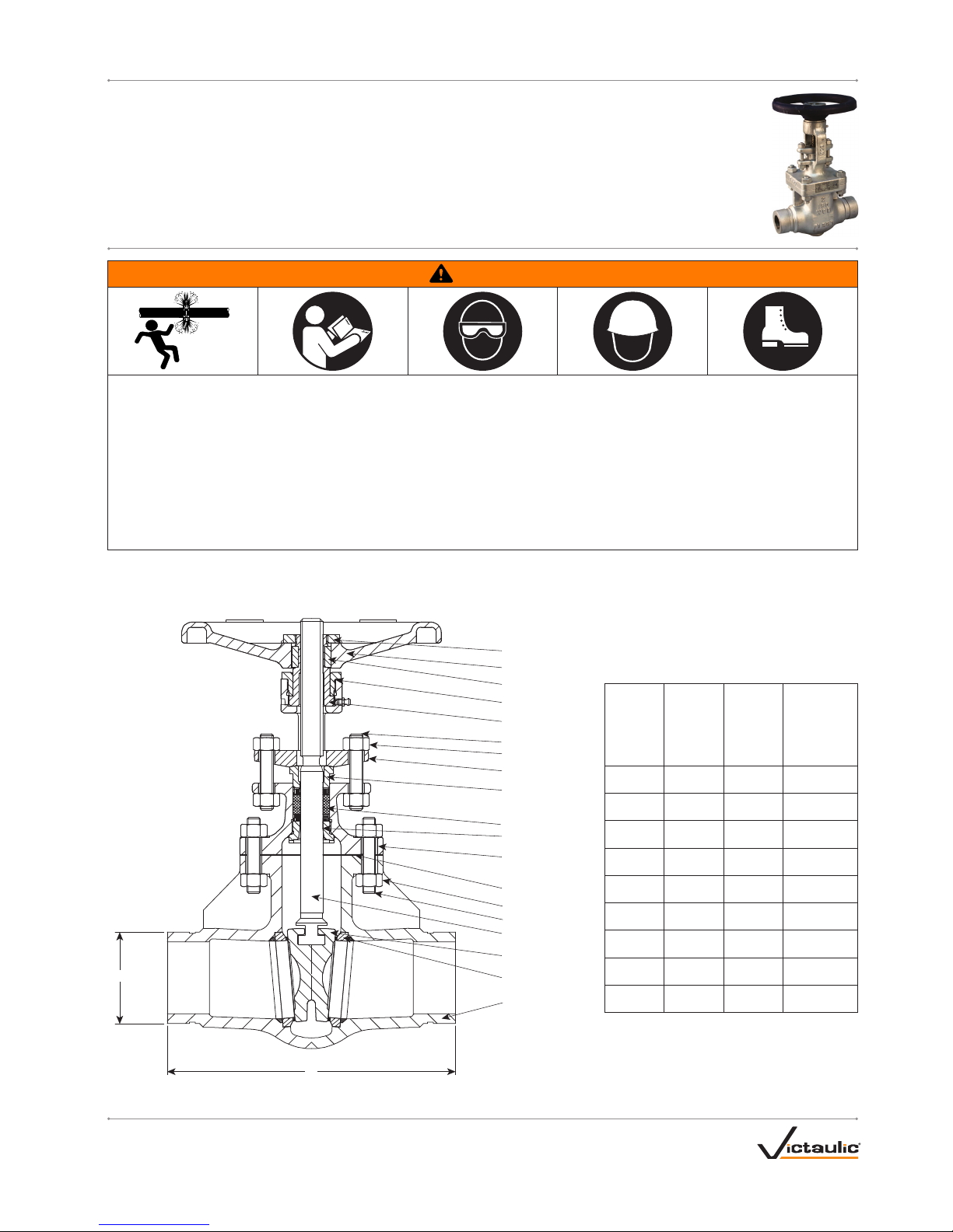
SECTION VIEW DRAWING, DIMENSIONS, AND WEIGHTS
Handwheel Nut
Handwheel
Key
Threaded Bushing
Stem Nut
Bolt
Nut
Gland Flange
Gland
Gland Packing
Back Seat Bushing
Bonnet
Nut
Bolt
Gasket
Stem
Flexible Wedge
Seat Ring
Valve Body
A
“OD”
Nominal
Size
inches
DN
Actual
Outside
Diameter
"OD"
inches
mm
"A"
inches
mm
Approximate
Weight Each
lbs
kg
2 2.375 8.54 31
DN50 60.3 217 14
2 ½
2.875 9.50 46
73.0 241 21
DN65
3.000 11.1 4 53
76.1 283 24
3 3.500 11.1 4 53
DN80 88 .9 283 24
4 4.500 12.01 77
DN10 0 114 .3 305 35
DN125
5.500 15.0 0 121
139. 7 381 55
6.500 15.8 7 14 8
165 .1 403 67
6 6.625 15.8 7 14 8
DN150 168 .3 403 67
8 8.625 16. 50 265
DN200 219.1 419 12 0
Page 2
I-871INSTALLATION INSTRUCTIONS
Victaulic® Series 871 Gate Valve
For complete contact information, visit victaulic.com
I-871 10176 REV A UPDATED 02/2017 Z000871000
VICTAULIC IS A REGISTERED TRADEMARK OF VICTAULIC COMPANY AND/OR ITS AFFILIATED ENTITIES IN THE
UNITED STATES AND/OR OTHER COUNTRIES. © 2017 VICTAULIC COMPANY. ALL RIGHTS RESERVED.
IMPORTANT INFORMATION
• The Series 871 is a flexible-wedge, metal-seated valve that is
designed for bidirectional shutoff service and is suitable for use in
saturated steam services. THIS VALVE IS NOT DESIGNED FOR
THROTTLING SERVICES.
• For complete valve ratings and applications, refer to Victaulic
publication 100.12, which can be downloaded at victaulic.com.
DO NOT exceed the performance capabilities listed in Victaulic
publication 100.12.
• Verify that there is adequate clearance around the valve for
operating and maintenance activities.
• The valve can be mounted in vertical and horizontal runs. For
horizontal pipe, the valve shall be installed with the stem in the
vertical "UP" position (handwheel pointing upward).
• Verify that proper pipe supports are in place to prevent strain on
the valve. The piping shall be laid out so that no thrust or bending
forces act on the valve body during operation.
• Verify that the piping is aligned and supported properly before
attempting to install the valve.
• The valve is supplied from the factory with a high-temperature
paint that may feel sticky to the initial touch. The paint is designed
to harden when exposed to higher temperatures.
• When painting a piping system, DO NOT apply paint to the stem
and bolts/nuts.
• Use lockout methods to prevent unauthorized operation of the
valve.
• DO NOT stand on or use the handwheel as a suppor t point.
• DO NOT over-torque the handwheel to force the valve into the
"CLOSED" position. Refer to the "Torque Limitations" table on this
page.
Handling
• The valve shall remain in the "CLOSED" position during handling.
• To prevent damage to the seats and sealing surfaces of the valve
body, the plastic shipping caps shall remain in place until the time
of installation.
• Refer to the weights listed on the opposite side of this page.
Verify that proper lifting equipment is available for handling larger,
heavier valve sizes. Lift the valve by placing straps around the
body. DO NOT lift or suspend the valve by the handwheel.
Storage
• Victaulic strongly recommends indoor storage of the valve. If
outdoor storage is required, the valve shall be stored in the
original shipping container and then covered completely with a
weatherproof tarp.
• The shipping caps shall remain in place to prevent debris from
entering the valve body during storage.
• The valve shall remain in the "CLOSED" position during storage.
• The valve shall be stored with the stem in the vertical "UP" position
(handwheel pointing upward).
INSTALLATION
WARNING
• The Series 871 Gate Valve shall be installed ONLY with Style
870 Rigid Couplings and pipe or fittings that are prepared to
Victaulic OGS-200 Specifications.
• DO NOT install the valve with any other coupling or with pipe/
fittings that are prepared to any other groove specification.
Failure to follow these instructions may cause joint failure,
resulting in death or serious personal injury and property damage.
1. Prior to installation, check the valve for any damage. DO NOT use
the valve if any damage is present.
2. Remove the plastic shipping caps from the valve body. To prevent
damage to the sealing surfaces of the valve body, DO NOT use any
sharp instruments to remove the shipping caps.
3. Verify that the valve is in the "CLOSED" position.
4. Install the valve by using two Victaulic Style 870 Rigid Couplings
and pipe or fittings that are prepared to Victaulic OGS-200
Specifications. Refer to the I- 870 installation instructions for
complete installation requirements. The I-870 is shipped with the
coupling and can be downloaded at victaulic.com.
5. Place the system into service af ter all installation requirements
have been met.
OPERATION
1. Operate the valve by turning the handwheel in the counter-
clockwise direction (top view) to the "OPEN" position, then by
turning the handwheel in the clockwise direction (top view) to the
"CLOSED" position. Repeat this process several times to verify
proper operation. NOTE: When the valve is in the fully "OPEN"
position, turn the handwheel a quarter turn in the clockwise
direction to prevent the stem/threads from locking up due to
thermal expansion.
Torque Limitations
Nominal
Size
inches/DN
Actual Outside
Diameter
inches/mm
Maximum Torque to Reach
Fully "OPEN" Position or
Fully "CLOSED" Position
ft-lbs/N•m
2 2.375 24
DN50 60.3 32
2 ½, DN65, 3/DN80
2.875, 3.000, 3.500 38
73.0, 76.1, 88.9 52
4 4. 500 65
DN10 0 114. 3 88
DN125
5.500 106
139. 7 144
6 6.500 & 6.625 106
DN150 165.1 & 168 . 3 14 4
8 8.625 180
DN200 219.1 244
INSPECTION
Inspect the valve on a frequency required by the building owner or their
representative.
1. Verify that there is no leakage from the gland. If necessary, tighten
the nuts at the gland flange evenly by alternating sides.
2. If the handwheel becomes loose, open the valve by turning the
handwheel one to two turns in the counterclockwise direction, then
tighten the handwheel nut.
 Loading...