

Page 1
HANG THESE INSTRUCTIONS ON THE
INSTALLED VALVE FOR FUTURE REFERENCE
WARNING
• Read and understand all instructions before attempting to install, remove, adjust, or perform maintenance on any Victaulic piping products.
• Depressurize and drain piping systems before attempting to install, remove, adjust, or perform maintenance on any Victaulic piping
products.
• Wear safety glasses, hardhat, and foot protection.
• Save this installation, operation, and maintenance manual for future reference.
Failure to follow instructions and warnings could cause system failure, resulting in death or serious personal injury and property damage.
I-867-42TINSTALLATION, OPERATION, AND MAINTENANCE MANUAL
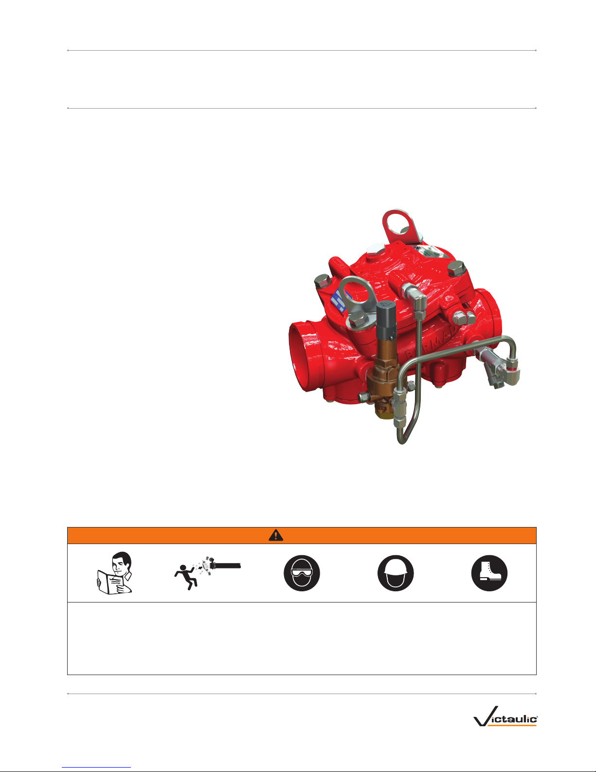
867-42T Pressure Reducing Valve
I- 867- 42T
REV_B
Page 2

Page 3

I-867-42T / Pressure Reducing Valve / Installation, Operation, and Maintenance Manual
TABLE OF CONTENTS
Hazard Identification ..................................4
Safety Instructions ................................... 4
Introduction ........................................4
Pressure and Flow Ratings ..............................5
Head Loss .........................................5
Installation .........................................6
Operation ..........................................7
Start Up..............................................8
Readjusting ...........................................8
Maintenance And Inspection Tests ........................9
Weekly Inspection ......................................9
Monthly Inspection And Test ..............................9
Troubleshooting......................................9
Difficulty In Performance ..............................9
I- 867- 42T_ 3
REV_B
Page 4

I-867-42T / Pressure Reducing Valve / Installation, Operation, and Maintenance Manual
HAZARD IDENTIFICATION
Definitions for identifying the various hazard levels are provided below.
This safety alert symbol indicates important safety messages.
When you see this symbol, be alert to the possibility of
personal injury. Carefully read and fully understand the
message that follows.
DANGER
• The use of the word “DANGER” identifies an immediate
hazard with a likelihood of death or serious personal injury
if instructions, including recommended precautions, are not
followed.
WARNING
• The use of the word “WARNING” identifies the presence
of hazards or unsafe practices that could result in death or
serious personal injury if instructions, including recommended
precautions, are not followed.
CAUTION
• The use of the word “CAUTION” identifies possible hazards or
unsafe practices that could result in personal injury and product
or property damage if instructions, including recommended
precautions, are not followed.
NOTICE
• The use of the word “NOTICE” identifies special instructions that
are important but not related to hazards.
SAFETY INSTRUCTIONS
WARNING
• An experienced, trained installer
must install this product in
accordance with all instructions.
These i nstructions contain important
information.
• Depressurize and drain the piping
system before attempting to install,
remove, adjust, or maintain any
Victaulic piping products.
Failure to follow these instructions
can cause product failure, resulting in
death or serious personal injury and
property damage.
1. Read and understand all instructions before proceeding with the
installation, operation, and maintenance of this valve. For proper
operation and approval, the 867-42T valve and accessories
must be installed in accordance with the specific instructions included
with the shipment.
2. Use only recommended accessories. Accessories and equipment
that are not approved for use with this valve may cause improper system
operation.
3. Wear safety glasses, hardhat, foot protection, and hearing
protection. Wear hearing protection if you are exposed to long periods of
noisy jobsite operations.
4. Prevent back injury. Large and pre-trimmed valves are heavy
and require more than one person (or mechanical lifting equipment)
to position and install the assembly. Always practice proper lifting
techniques.
5. Avoid using electrically powered tools in dangerous environments.
When using electrically powered tools for installation, ensure that the
area is moisture-free. Keep the work area well lit, and allow enough
space to accommodate proper installation of the valve, trim, and
accessories.
6. Watch for pinch points. Do not place fingers under the valve body
where they could be pinched by the weight of the valve. Use caution
around spring-loaded components.
7. Keep work areas clean. Cluttered areas, benches, and slippery floors
can create hazardous working conditions.
INTRODUCTION
NOTICE
• Drawings and/or pictures in this manual may be exaggerated for
cla rity.
• The valve, along with this operating and maintenance manual,
contains trademarks, copyrights, and/or patented features that
are the exclusive property of Victaulic.
The 867-42T is an elastomeric, line-pressure driven, pilot-operated
pressure control valve that is designed for fire protection systems.
The 867-42T reduces high upstream pressure to a precise, preset,
stable downstream pressure. The 867-42T is suitable for control of
fire pump discharge. It is also suitable for preventing over-pressure in
sprinklers, hose stations, and other discharge devices.
Valve sizes covered by this manual include 1.5 through 10 inches. Max
recommended pressure differential: 175 psi (12 bar) when normal inlet
operation pressure is below 330 psi/23 bar. Max recommended pressure
differential: 200 psi (14 bar) when normal inlet operation pressure is
above 330 psi/23 bar.
I- 867- 42T_ 4
REV_B
Page 5

I-867-42T / Pressure Reducing Valve / Installation, Operation, and Maintenance Manual
PRESSURE AND FLOW RATINGS
The 867-42T pressure reducing valve, sizes 1.5-, 2-, 2.5-, 3-, 4-, 6-, 8-, and 10-inch, are rated for the following pressure and flow capacities detailed
in Table 1.
NOTE: Maximum flows below are at a differential of 175 psi (12 bar). Contact Victaulic if your system has greater than 175 psi differential.
Table 1: Pressure Ratings and Flow Capacity
Valve Size
inches/mm
1.5
40
2
50
3
80
4
100
6
150
8
200
10
250
Max. inlet pressure
psi/bar
365 25365
25
365 25365
25
365
25
365 25365
25
Outlet pressure
setting range
psi/bar
30–175
2–12
30–175
2–12
30–175
2–12
30–175
2–12
30–175
2–12
30–175
2–12
30–175
2–12
Max. recommended flow
GPM / m³/h
106 24172
39
360 82640
145
1450
330
2570
580
4000
910
Min. recommended flow
GPM / m³/h
20
5
20
5
20
5
20
5
20
5
20
5
45
10
Pilot valve model
2-PB 2-PB 2-PB 2-PB 2-PB
2-UL/
2-PBL
2-UL/
2-PBL
Recommended relief valve
in/mm
¾
20
¾
20
1 ½
40
2
50
3
80
3
80
4
100
HEAD LOSS
The minimum ∆P across the valve is 5.8 psi (0.4 bar). In cases where the inlet pressure falls below or is equal to the intended outlet pressure, the
outlet pressure shall be determined according to Table 2: Frictional Resistance.
In the case of zero (static) flow through the valve, the maximum increase in the downstream (outlet) pressure above the set pressure of the valve will
not exceed 7.2 psi (0.5 bar).
Table 2: Frictional Resistance
Valve Size Full Open Equivalent Length of Pipe
Nominal Size
inches/DN
Actual Ouside Diameter
inches/mm
Flow Coefficient
C v / K
v
feet/meters
1 ½
DN40
1.900
48.3
79
68
7
2
2
DN50
2.375
60.3
92
80
16
5
2 ½
2.875
73.0
116
100
28
9
3
DN80
3.500
88.9
219
190
23
7
4
DN100
4.500
114.3
398
345
30
9
6
DN150
6.625
168.3
912
790
49
15
8
DN200
8.625
219.1
1160
1160
89
27
10
DN250
10.750
273.0
1662
1355
203
62
Note 1: Valve Equivalent L ength Value (Steel P ipe), for use in hydraulically c alculated syste m
I- 867- 42T_ 5
REV_B
Page 6
I-867-42T / Pressure Reducing Valve / Installation, Operation, and Maintenance Manual
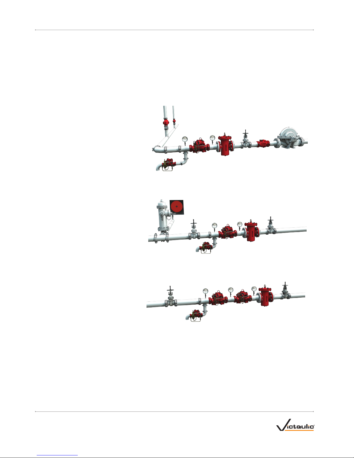
INSTALLATION
A typical installation of the 8 67-42T features a pilot valve for the automatic reduction of water pressure from a high upstream value to a preset lower
downstream value, regardless of fluctuating upstream pressure or flow. The actuator design ensures quick and smooth valve action.
Installed singly, the 867-42T provides a standard pressure-reducing system. Installed in parallel, two 867-42T valves provide high flow rates,
redundancy, and zero downtime for maintenance. Installed in series, two 867-42T valves provide a two-stage, high reduction in pressure and/or
added protection to a reduced-pressure zone.
Sprinkler System Pressure Reduction
• Reduces a high, unstable pressure supply
to a preset, stable system pressure.
• Sets the sprinkler pressure to suit the system design
• For pressure control of zones
Hose System Pressure Reduction
• Reduces a high/unstable pressure supply
to suit fire hose pressure
• Limits fire hose pressure to 100 psi/7 bar
to meet NFPA 14 regulations for maximum
allowable hose pressure supply.
Two-Stage Pressure Reduction
• High pressure reduction to a low, preset,
stable system pressure (when required pressure
reduction differential is more than 175 psi/12 bar)
• Backup pressure reducing valve in-line to a
master valve to secure pressure zone rating
at all times.
Figure 1 Installation Drawing
I-867-42T_6
REV_B
Page 7

I-867-42T / Pressure Reducing Valve / Installation, Operation, and Maintenance Manual
OPERATION
The 867-42T pressure control valve reduces water pressure
automatically from a high inlet pressure to a lower, pre-set outlet
pressure. The outlet set pressure can be adjusted with the pilot
valve adjusting screw (Figure 2, call out 5). The valve operates
under both flow and static conditions. The pressure-reducing pilot
valve (Figure 2, call out 4) senses changes in outlet pressure
(Figure 2, call out 6) and modulates the control valve to maintain
the pre-set outlet pressure.
When outlet pressure rises above the pre-set pressure, the pilot valve
throttles, enabling pressure to accumulate in the control chamber
(Figure 2, call out 1). This causes the control valve to close further and
reduce outlet pressure. When outlet pressure falls, the pilot valve opens
wider, releasing pressure from the control chamber. This causes the
control valve to open wider and increase outlet pressure. An integral
restrictor (Figure 2, call out 3A) controls the valve’s closing speed.
For valves 8 inches and larger, an adjustable needle valve (Figure 2,
call out 3B) is provided.
Figure 2 Operation Drawing
Valve Closed Valve Open (pressure relief)
4
5
6
2
3
A
1
Valve Closed Valve Open (pressure relief)
2
3B
6
4
5
1
Valves 6 inches
and smaller
Valves 8 inches
and larger
I- 867- 42T_ 7
REV_B
Page 8

I-867-42T / Pressure Reducing Valve / Installation, Operation, and Maintenance Manual
START UP
When performing this procedure, refer to Figure 2.
1. Open a hydrant, relief valve, drain valve, or other flow-consumer
downstream of the 867-42T pressure reducing valve, creating a
system demand.
2. Fully open upstream indicating valve.
3. Gradually open downstream indicating valve to fully open, allowing
flow through the 867-42T valve.
4. Wait for downstream pressure stability.
5. Slowly close the flow-consumer that was opened in step #1 above
to fully closed.
6. There should be no system flow; the downstream pressure should
be between the factory the pre-set pressure and up to 10%
different. Follow the readjusting procedure if needed to be changed.
READJUSTING
The pilot valve is factory pre-set according to the stated demands of the
customer.
The pre-set is clearly indicated on the pilot valve tag. If readjustment to
either the pressure or valve response is required, perform the following
steps.
1. When readjusting the outlet pressure, the inlet pressure should be
at least 20 psi (1.4 bar) higher than the set outlet pressure.
2. The flow rate during adjustment should be as close as possible to
the systems design flow rate. Where this is not possible, at least a
minimal flow is essential.
3. Free the tension between the adjusting screw on the pressure
reducing pilot valve (Figure 2, call out 4) and the fastening nut by
turning the fastening nut counterclockwise.
4. By alternately turning the adjusting screw on the pilot valve a
half turn and then reading the downstream pressure, gradually
adjust the pressure counterclockwise to decrease the downstream
pressure, or clockwise to increase the downstream pressure.
5. Repeat the start up procedure in the previous section.
CAUTION: If needle valve is furnished (optional), changes in
the adjustment of the needle valve will have impact on the valve
performance. The needle valve is factory set at one-half turn open to one
and one-half turn open. The maximum number of turns is 3 from fully
closed to fully open. More than 3 turns open might cause the valve to
perform at less than optimal functioning. Perform Start Up step 5 with
this in mind.
I-867-42T_8
REV_B
Page 9

I-867-42T / Pressure Reducing Valve / Installation, Operation, and Maintenance Manual
MAINTENANCE AND INSPECTION TESTS
NOTICE
• Any activities that require taking the valve out of service may
eliminate the fire protection provided.
• Consideration of a fire patrol should be given for the affected
areas.
• Before servicing or testing the system, notify the authority having
jurisdiction.
Prior to turning off any valves or activating any alarms, notify local
security guards and the central alarm station, if used, so that a false
alarm will not be signaled.
In any of the following inspections or testing procedures, if an abnormal
condition exists, see the troubleshooting section for possible cause and
corrective action.
The 867-42T valve is to be inspected, tested, and maintained in
accordance with this manual and with NFPA 25.
WEEKLY INSPECTION
1. The system should be inspected under flow conditions.
2. Check that the main valve, pilot system, accessories, tubing, and
fittings are all in good condition, are free of damage, and are not
leaking.
3. The fastening nut of the pilot valve adjusting screw (Figure 2, call
out 5) should be fastened tightly.
4. For circulation-type installations, verify that sufficient water is
flowing through the valve when the fire pump is operating at
shut-off pressure (churn) to prevent the pump from overheating.
5. Verify that the pressure upstream of the relief valve fittings in the
fire pump discharge piping does not exceed the pressure for which
the system components are rated.
MONTHLY INSPECTION AND TEST
1. Complete weekly inspection.
2. During the monthly fire pump flow test, verify that the pressure
relief valve is correctly set to relieve at the appropriate pressure and
to close below the pressure setting.
TROUBLESHOOTING
Problem Possible Cause Solution
Valve fails to regulate. Needle valve not properly adjusted. Factory set at ½ or 1½ open. Adjust.
Pulsates or hunts. Slowly adjust needle valve until pulsation stops.
Air trapped in main valve cover.
Loosen cover tube tting at the highest point, allow the air
to escape, and re-tighten.
Filter screen blocked.
Remove lter’s cap and screen to clean. Filter might be
insucient. See note below.
Valve fails to open. Insucient inlet pressure. Check/create inlet pressure.
Pilot is adjusted too high. Turn adjusting screw CCW on pilot.
Valve fails to seal inlet
pressure.
Filter screen blocked. Remove lter’s cap and screen to clean. Filter might be
insucient. See note below.
Debris trapped in main valve. Remove and inspect actuator assembly. Check seat. Check for
foreign bodies. Rinse at high ow rate.
Diaphragm in main valve is leaking.
Open the valve cover and inspect diaphragm. If damaged,
replace.
Diaphragm in pilot valve is leaking.
NOTE: Mark “F” – Large Filter
In cases where the filter screen frequently becomes blocked, install a filter with filtration capacity of at least 80 mesh / 250 µm.
DIFFICULTY IN PERFORMANCE
Where difficulty in performance is experienced, the manufacturer or an
authorized representative should be contacted to determine if any field
adjustment is to be made.
I- 867- 42T_ 9
REV_B
Page 10

I-867-42TINSTALLATION, OPERATION, AND MAINTENANCE MANUAL
867-42T Pressure Reducing Valve
For complete contact information, visit victaulic.com
I-867-42T 9680 REV B UPDATED 11/2016
VICTAULIC IS A REGISTERED TRADEMARK OR TRADEMARK OF VICTAULIC COMPANY AND/OR ITS AFFILIATED ENTITIES
IN THE UNITED STATES AND/OR OTHER COUNTRIES. © 2016 VICTAULIC COMPANY. ALL RIGHTS RESERVED.
 Loading...