

Victaulic 809N Installation Instructions Manual
I-809N
I-809NINSTALLATION INSTRUCTIONS
REV_ A
Style 809N High-Pressure Coupling for Ring Systems
IMPORTANT INFORMATION
WARNING
• Read and understand all instructions before attempting to install, remove, adjust, or maintain any Victaulic piping products.
• Depressurize and drain the piping system before attempting to install, remove, adjust, or maintain any Victaulic piping products.
• Wear required personal protective equipment during the welding process, and follow all jobsite regulations regarding welding safety.
• Wear safety glasses, hardhat, and foot protection during the coupling installation process.
• DO NOT attempt to install this product on pipe that is grooved (roll or cut) or that contains a weld bevel. Pipe ends shall be square cut.
• DO NOT attempt to install this product with rings supplied by other manufacturers.
Failure to follow these instructions could result in death or serious personal injury and property damage.
The Style 809N High-Pressure Coupling for Ring Systems is designed for installation on pipe that is prepared with rings supplied by Victaulic. Refer to
Victaulic publication 15.03 for allowable pipe materials and joint performance.
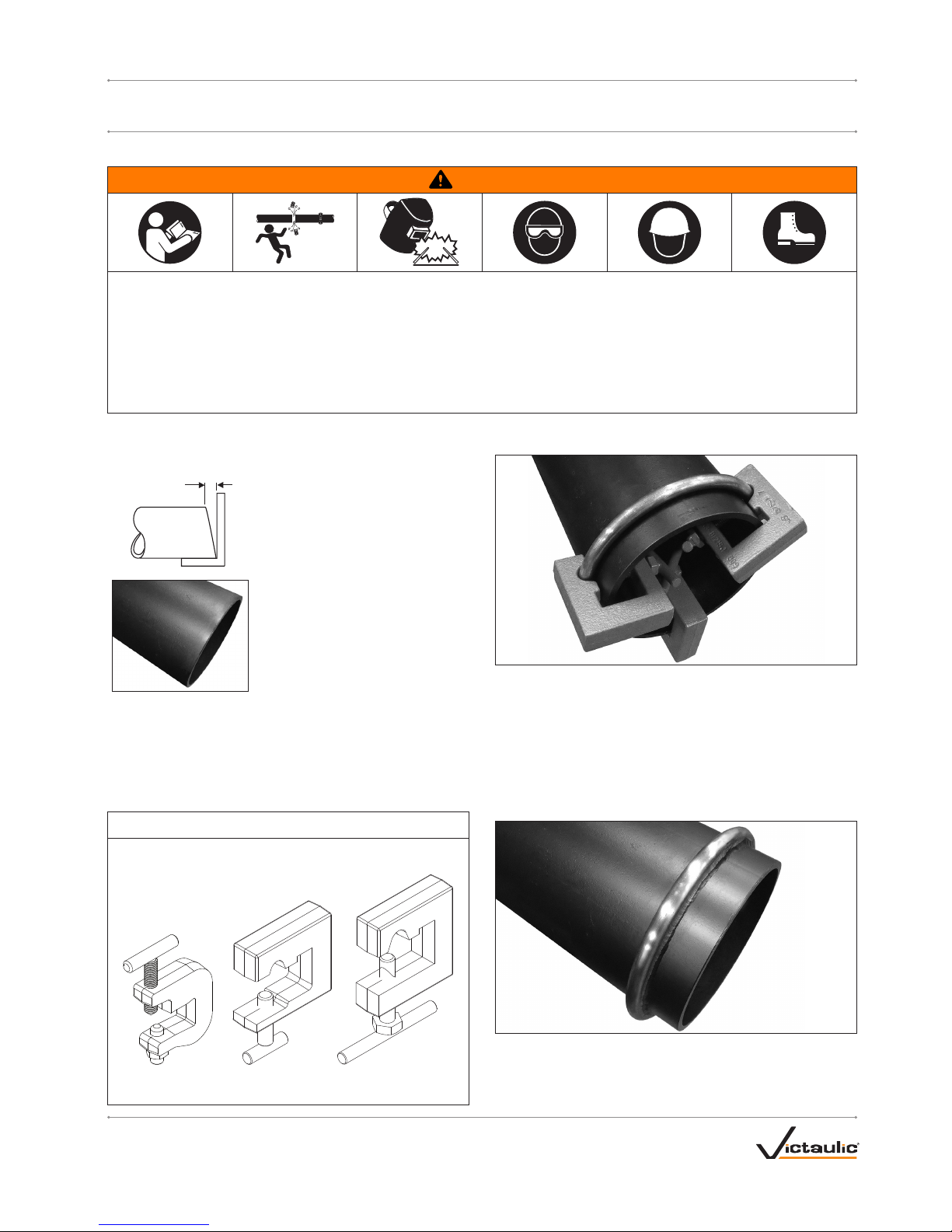
PIPE PREPARATION/RING ATTACHMENT
"S" Max.
1a. SQUARE CUT THE PIPE ENDS: The
maximum allowable tolerance from squarecut pipe ends (“S” dimension shown) is
⁄ inch/1.6 mm. This is measured from
the true square line.
1b. INSPECT PIPE ENDS PRIOR TO
RING ATTACHMENT: The outside
surface of the pipe ends (approximately
2 inches/51 mm back from the ends) shall
be smooth and free from indentations and
projections. All oil, grease, loose paint, dirt,
and cutting particles shall be removed.
2a. INSTALL RING ON PIPE: Spread the ring apart using appropriate
tooling at the ring opening (refer to the ring detail on page 2). Slide the
ring over the pipe end.
2b. POSITION RING: Remove the tooling and position the ring at the
required distance (refer to page 2 for the “B” dimension, which is the
required distance from the edge of the ring to the pipe end).
NOTICE
• Use Victaulic ring clamps to hold the rings at the appropriate
location on the pipe during tack welding.
Ring Clamp for
4-inch/114.3-mm Pipe
Ring Clamp for
6-inch/168.3-mm and
8-inch/219.1-mm Pipe
Ring Clamp for
10-inch/273.0-mm Pipe
2c. CLAMP RING IN POSITION: Hold the ring in position by applying
a ring clamp at three locations around the pipe circumference. DO NOT
cover the butt ends of the ring with a ring clamp.
2d. TACK WELD THE RING: Tack weld the ring to the pipe in enough
locations so that the ring does not shift out of position when the ring
clamps are removed.
2e. REMOVE RING CLAMPS AND COMPLETE WELD PROCEDURE:
Remove ring clamps. Weld around the entire circumference on both
sides of the ring. Refer to page 2 for complete weld requirements.
3a. INSPECT RING: The ring shall not contain any weld splatter or arc
strikes.
3b. INSPECT WELDS: Weld size and geometry shall meet the
requirements on page 2.
I-809N_2
REV_ A
I-809N / Style 809N High-Pressure Coupling for Ring Systems / Installation Instructions
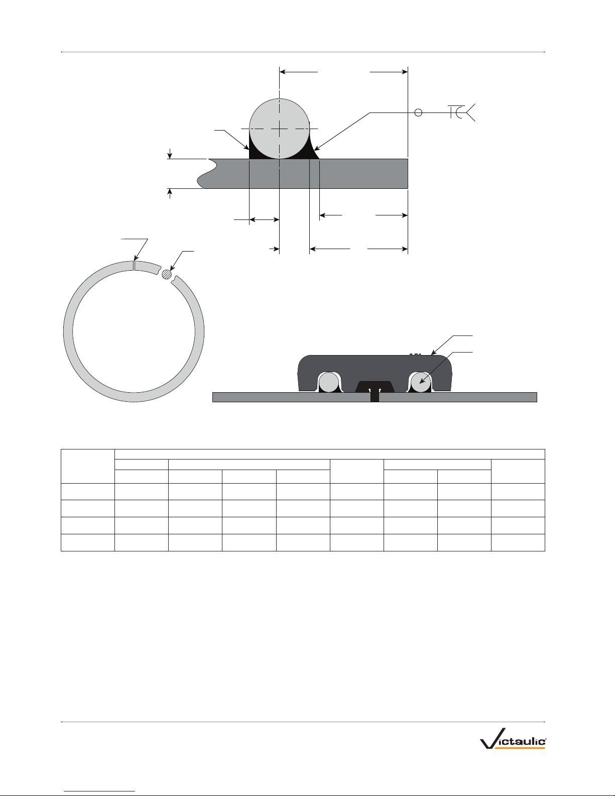
RING DETAIL
RING WELD DETAIL
MECHANICAL JOINT DETAIL
Style 809N Coupling
Ring
("Ø A")
SEE NOTE 4
"X" MIN
"B"
"T"
SEE NOTE 6
(”S”)
"E1"
("S")
"E2"
SEE NOTE 9
S(E1)
G
S(E2)
SEE NOTES 3 AND 8
Ring Opening
WELD SIZE TABLE
Nominal Pipe
Size inches /
Actual mm
Dimensions - inches/millimeters
Ring "B"
"S"
Weld Size
"X" Minimum("Ø A") Basic Maximum Minimum "E1" "E2"
4 ⁄ 1.0 0 1.03 0.97 ⁄ ⁄ ⁄ 0.91
114 .3 9.5 25.4 26.2 24.6 4.8 4.8 4.8 23.0
6 ½ 1. 22 1.2 5 1.19 ¼ ¼ ¼ 1.10
168 .3 12. 7 31. 0 31. 8 30.2 6 .4 6.4 6.4 27. 8
8 ⁄ 1.2 2 1. 25 1.19 ⁄ ⁄ ⁄ 1.10
219.1 15.9 31. 0 31.8 30.2 7. 9 7.9 7. 9 2 7.8
10 ¾ 1. 22 1. 25 1.19 ⁄ ⁄ ⁄ 1.10
273.0 19.1 31. 0 31.8 30.2 9.5 9.5 9. 5 2 7. 8
NOTES:
1. Victaulic ring to be supplied unpainted with a rust-inhibiting coating applied. Check rings to verify that all oil, grease, and dirt is
removed prior to welding.
2. Victaulic ring material: ASTM A108 Grade 1018, cold-rolled carbon steel
3. Weld metal: E70XX or greater
4. This area shall be free from indentations, projections, and weld splatter to ensure a leak-tight seal for the gasket. All oil, grease,
and dirt shall be removed.
5. Pipe material: Refer to Victaulic publication 15.03, which can be downloaded at victaulic.com
6. Pipe thickness: Refer to Victaulic publication 15.03, which can be downloaded at victaulic.com
7. Weld procedure by others
8. Take precautions during welding to keep heat buildup low. Excessive heat buildup can result in ring diameter shrinkage after
cooling to ambient temperature.
9. Final weld shall not extend past the edge of the ring. Excess weld material will compromise the joint.
 Loading...