

Page 1
WARNING
• Read and understand all instructions before attempting to install any Victaulic piping products.
• Depressurize and drain the piping system before attempting to install, remove, adjust, or perform maintenance on any Victaulic products.
• Wear safety glasses, hardhat, and foot protection when working with Victaulic piping products.
• Any activities that require taking the valve out of service may eliminate the fire protection provided by the system. Before removing the
valve from service, notify the authority having jurisdiction. Consideration of a fire patrol should be given for the affected areas.
Failure to follow these instructions could result in serious personal injury and/or property damage.
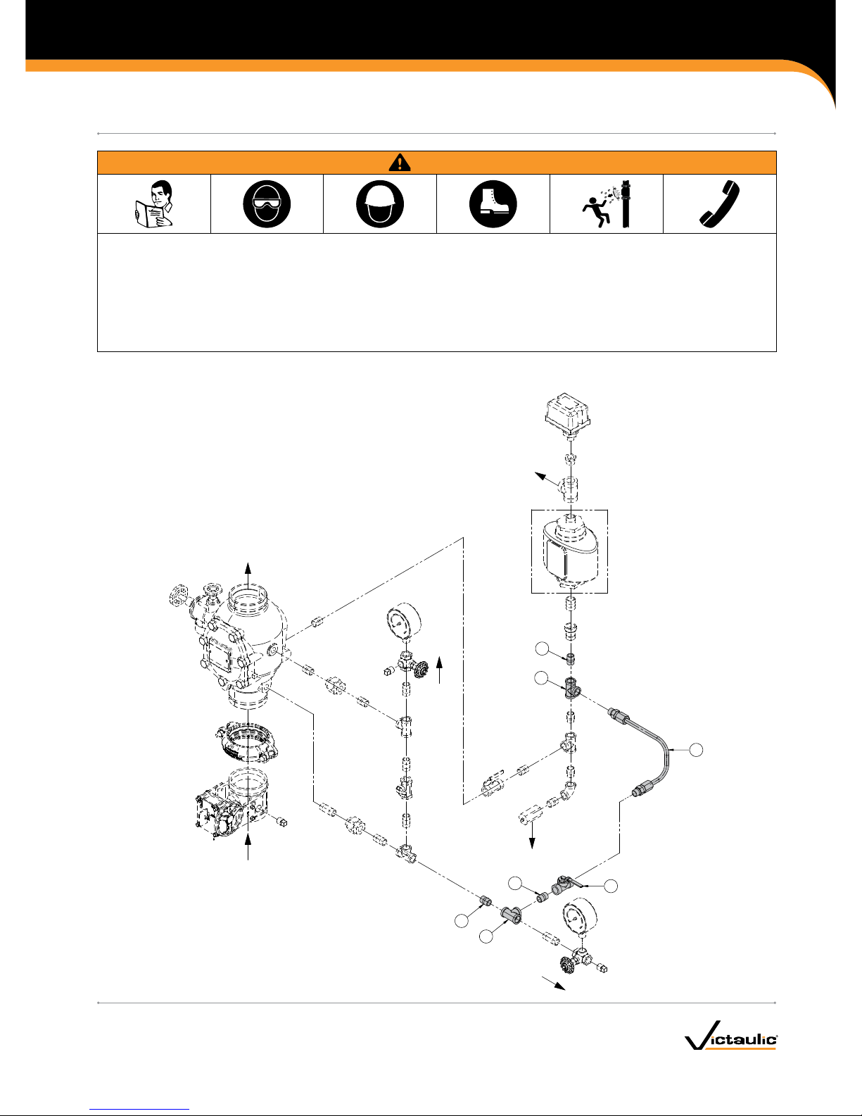
EXPLODED VIEW DRAWING - AUXILIARY WATER MOTOR ALARM TEST VALVE KIT
4
TO SYSTEM
WATER
SUPPLY
TO WATER
MOTOR ALARM
TO
DRAIN
NORMALLY
CLOSED
(LOCKABLE)
3
4
4
3
1
2
Bill of Materials
1 Auxiliary Water Motor Alarm Test Ball Valve
(Normally Closed - Lockable)
2 Flexible Stainless Steel Braided Hose
3 Female Tee
4 Close Nipple
I-751.VDS/KIT_1
Series 751 FireLock European Alarm Check Valve Stations
AUXILIARY WATER MOTOR ALARM TEST VALVE KIT
I-751.VDS/KITKIT INSTALLATION INSTRUCTIONS
www.victaulic.com
VICTAULIC IS A REGISTERED TRADEMARK OF VICTAULIC COMPANY. © 2009 VICTAULIC COMPANY. ALL RIGHTS RESERVED. PRINTED IN THE USA.
REV_A
Page 2
REMOVING THE SYSTEM FROM SERVICE
1. Notif y the authority having jurisdiction, remote station alarm
monitors, and those in the affected area that the system is being
taken out of service.
2. Close the water supply main control valve to take the system out of
service.
3. Open the system main drain valve, and allow the system to drain
completely. NOTE: It may be necessary to open the remote system
test valve (inspector’s test connection) and any auxiliary drains in
order to drain the system completely.
INSTALLATION OF THE AUXILIARY WATER MOTOR ALARM
TEST VALVE KIT
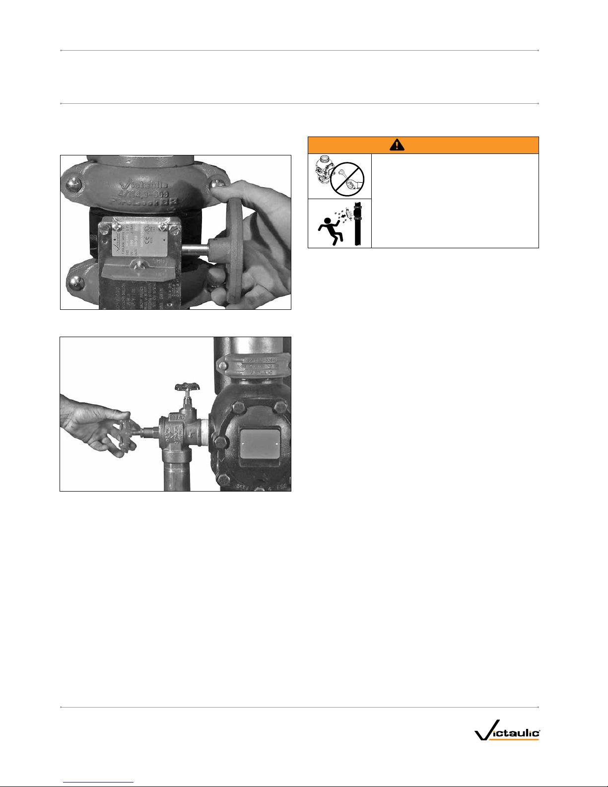
WARNING
• Make sure the valve is depressurized and
drained before attempting to remove any
trim from the valve.
Failure to follow this instruction could result
in serious personal injury and/or property
damage.
1. Make sure the valve is completely depressurized and drained.
2. Remove the trim at the locations designated in the exploded view
drawing on page 1.
3. Apply a small amount of pipe joint compound or Teflon* tape to
the external threads of all threaded pipe connections contained in
the kit. DO NOT get any tape, compound, or other foreign material
into the pipe connections.
4. Install the kit components, as shown in the exploded view drawing
on page 1.
5. Place the system back in service by following the “Placing
the System in Service” section of the I-751.VDS Installation,
Maintenance, and Testing Manual.
6. Check the connections for any leaks. If any leaks are present,
depressurize and drain the system and repair any leaks.
* Teflon is a registered trademark of the DuPont Company
I-751.VDS/KIT_2
Series 751 FireLock European Alarm Check Valve Stations
AUXILIARY WATER MOTOR ALARM TEST VALVE KIT
I-751.VDS/KIT
KIT INSTALLATION INSTRUCTIONS
www.victaulic.com
VICTAULIC IS A REGISTERED TRADEMARK OF VICTAULIC COMPANY. © 2009 VICTAULIC COMPANY. ALL RIGHTS RESERVED. PRINTED IN THE USA.
REV_A
Page 3

PERFORMING THE WATER MOTOR ALARM TEST
1. Notif y the authority having jurisdiction, remote station alarm
monitors, and anyone in the affected area that the water motor
alarm test will be performed.
2. Verify that the alarm line ball valve is open.
3. Open the auxiliary water motor alarm test ball valve.
3a. Confirm that mechanical and electrical alarms are activated and
that remote monitoring stations, if provided, receive an alarm
signal. NOTE: There may be a time delay if a Series 752 Retard
Chamber is installed.
4. Close the auxiliary water motor alarm test ball valve after proper
operation of all alarms is verified.
5. Confirm that all valves are in their normal operating positions (refer
to table below).
Valve Normal Op erating Positi on
System Test Valve Closed
System Main Drain Valve Closed
Water Supply Main Control Valve Open
Alarm Line Ball Valve Open (Lockable)
Auxiliary Water Motor Alarm Test Ball Valve Closed (Lockable)
WAT ER MOTOR
ALARM
SER IES 760
R
FM
APPROVED
VdS
To
System
Water
Supply
To
Drain
Alarm Line Ball
Valve (Normally
Open Lockable)
System Test Valve
(Normally Closed)
Water Supply Main
Control Valve
System Main Drain
Valve (Normally Closed)
Auxiliary Water Motor
Alarm Test Valve
(Normally Closed Lockable)
I-751.VDS/KIT_3
Series 751 FireLock European Alarm Check Valve Stations
AUXILIARY WATER MOTOR ALARM TEST VALVE KIT
I-751.VDS/KITKIT INSTALLATION INSTRUCTIONS
www.victaulic.com
VICTAULIC IS A REGISTERED TRADEMARK OF VICTAULIC COMPANY. © 2009 VICTAULIC COMPANY. ALL RIGHTS RESERVED. PRINTED IN THE USA.
REV_A
Page 4

Series 751 FireLock European Alarm Check Valve Stations
AUXILIARY WATER MOTOR ALARM TEST VALVE KIT
I-751.VDS/KITKIT INSTALLATION INSTRUCTIONS
I-751.VDS/KIT
For complete contact information, visit www.victaulic.com
I-751.VDS/KIT 5911 REV A UPDATED 10/2009 ZVDS751KIT
VICTAULIC IS A REGISTERED TRADEMARK OF VICTAULIC COMPANY. © 2009 VICTAULIC COMPANY. ALL RIGHTS RESERVED. PRINTED IN THE USA.
 Loading...