

Page 1
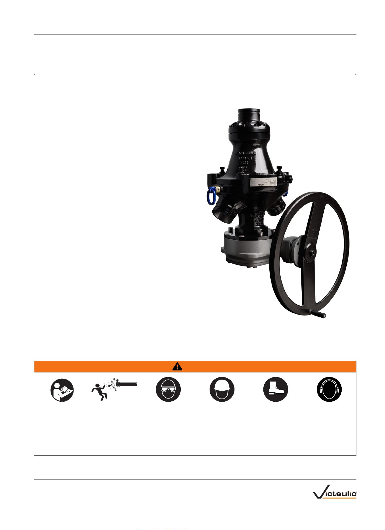
Series 725S Diverter Valve
I-725SINSTALLATION AND OPERATING INSTRUCTIONS
WARNING
• Read and understand all instructions before attempting to install any Victaulic products.
• Always verify that the piping system has been completely depressurized and drained immediately prior to installation, removal, adjustment,
or maintenance of any Victaulic products.
• Wear safety glasses, hardhat, foot protection, and hearing protection.
Failure to follow these instructions could result in death or serious personal injury and property damage.
REV_B
I-725 S
Page 2
I-725S / Series 725S Diverter Valve / Installation and Operating Instructions
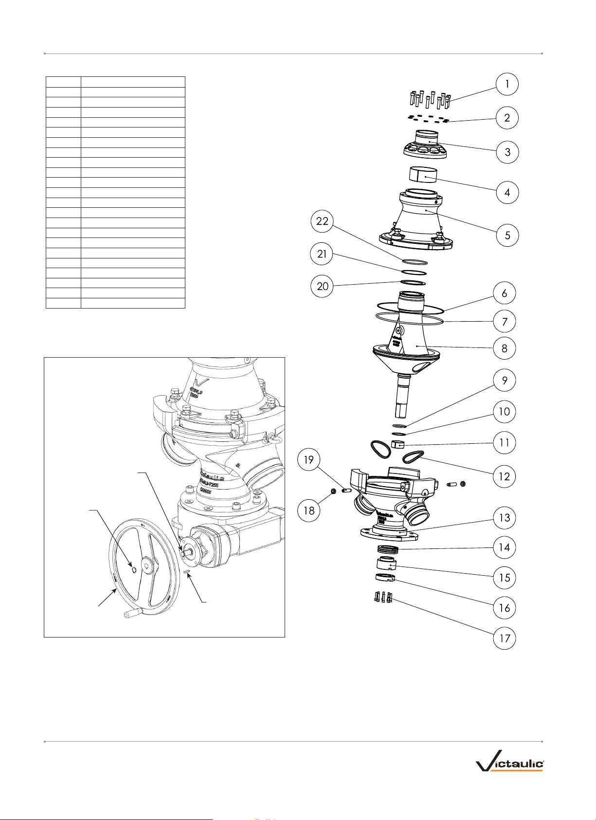
DIVERTER VALVE COMPONENTS
Item # Description
1 Hex Socket Head Cap Screw
2 Spring Lock Washer
3 Inlet Cap
4 Upper Shaft Bearing
5 Cover
6 O-Ring
7 Backup Ring
8 Plug
9 O-Ring
10 Backup Ring
11 Lower Shaft Bearing
12 Body Seal
13 Body
14 Thrust Bearing
15 Adjusting Nut
16 Counter Nut
17 Hex Socket Head Cap Screw
18 Hex Nut
19 Set Screw
20 Top S ea l
21 Backup Ring
22 O-Ring
ASSEMBLY OF THE HANDWHEEL
Gear Input Shaft
Circlip
Handwheel
Key
1. Place the key onto the gear input shaft.
2. Install the handwheel over the gear input shaft.
3. Attach circlip in front of the handwheel, onto the gear input shaft.
I-725 S_2
REV_B
Page 3

I-725S / Series 725S Diverter Valve / Installation and Operating Instructions
NOTICE
• Drawings and/or pictures in this manual may be exaggerated for clarity.
• The product, along with these installation and maintenance instructions, contains trademarks, copyrights, and/or patented features that are
the exclusive property of Victaulic.
INSTALLATION INFORMATION
Series 725S Diverter Valves are available with three different types of
Lifting
Lug
Lifting
Lug
Operator
ISO 5211
Mounting
Flange
pipe preparation, for use with three types of Victaulic products.
• Cut grooved pipe ends, for use with Victaulic EndSeal™ couplings
• Double grooved pipe ends, for use with Victaulic Style 80 8 couplings
• Pipe prepared with rings, for use with Victaulic Style 809 couplings
Series 725S Diverter Valves can be installed in horizontal or vertical
positions, or in any intermediate position that allows for access to the
actuator or gear operator.
Series 725S Diverter Valves and connecting piping must be supported
to prevent the joints from being subjected to bending loads, shear loads,
or any other external loads.
• Using both lifting lugs, support the valve to ensure balanced
loading. In addition, a cradle or cribbing can be used to provide
increased support.
• WELDING TO SERIES 725S DIVERTER VALVES AND
COUPLINGS IS NOT PERMITTED.
ACTUATOR SETUP
Always refer to the actuator manufacturer’s manual for complete setup
and operating requirements.
Actuators are designed to operate within the parameters specified in
the table below. Additional information will be required to determine
appropriate specifications for your system.
SERIES 725S HELPFUL INFORMATION
Operator/Actuator Performance
Size Manual (Gear Operator) Pneumatic Hydraulic Electric
Number of
Supply Air
Nominal
inches
DN
DN10 0 630 69 6.3 15 172 1.84
DN150 630 91 6.3 20 172 1.84
DN200 630 104 6.3 40 * 172 1.84
NOTE: For additional actuation requirements, contact Victaulic.
* for Australia only: 61 l/s
§
for Australia only: 192 RPM
†
electrical requirements vary based on voltage
Flow Position A
Flow Position B
4
6
8
to
80
80
109
Turns from
Hand Wheel
Dimensions
inches
mm
Rim Pull
lbf
N
Pressure
psi
bar
24.80 51 92 32
24.80 67 92 42
24.80 77 92 85
Flow
Rate
SFPM
l/s
RPM
109
100
90
§
Supply Fluid
Pressure
psi
bar
2500 30
2500 30
2500 30
Flow
Rate
gpm
l/s
RPM
2000 90
2000 90
2000 90
†
RPM
REV_B
I-725 S_3
Page 4

Series 725S Diverter Valve
I-725SINSTALLATION AND OPERATING INSTRUCTIONS
VALVE OPERATION
WARNING
• DO NOT actuate or operate the Series 725S Diverter Valve
with media in the system, or while the valve is pressurized. To
prevent permanent damage to internal valve components, the
system must be depressurized, flushed, and free of backfill
before attempting to index the valve.
Failure to follow these instructions may cause valve damage,
resulting in serious personal injury and property damage.
DIVERSION SERVICE
For a directional change of backfill flow to stopes, complete the
following steps.
1. Shut down backfill pump/gravity feed system.
2. Flush piping system with clean water to remove build up on pipes
and valve.
3. Once flushing is complete, rotate the diverter plug from outlet
“A” to outlet “B”. (Refer to the “Series 725S Helpful Information”
table for actuation input requirements. Also, refer to the actuation
manufacturer’s manual provided with the valve.)
Alternatively, follow the method shown in the “Flush Service”
section of these instructions.
4. At operator’s option, flush the system prior introducing backfill
to identify and clear flow path blockages as well as providing
confirmation the backfill will be transported to the desired location.
CAUTION
• The Series 725S Diverter Valve should only be used when the
diverting plug is fully aligned with either outlet port. The valve
should never be used in a partially open position, or with the
diverting plug rotated 90 degrees in an attempt to shut off flow.
Failure to follow these instructions will cause premature valve
wear and leakage, resulting in property damage and voiding any
Victaulic warranty.
5. Resume backfill operation.
FLUSH SERVICE
When using one outlet for backfill service and one outlet for flush water
dump to a sump collection area, complete the following steps.
1. Shut down backfill pump/gravity feed system.
2. Flush piping system with clean water to remove build up on pipes
and valve.
3. Operate the valve from backfill service direction to the opposing
port, allowing the flush water to enter a sump collection area.
(Refer to the “Series 725S Helpful Information” table for actuation
input requirements. Also, refer to the actuation manufacturer’s
manual provided with the valve.)
CAUTION
• The Series 725S Diverter Valve should only be used when the
diverting plug is fully aligned with either outlet port. The valve
should never be used in a partially open position, or with the
diverting plug rotated 90 degrees in an attempt to shut off flow.
Failure to follow these instructions will cause premature valve
wear and leakage, resulting in property damage and voiding any
Victaulic warranty.
4. Once flushing is complete, return valve to backfill service location
and resume backfill operation.
DUMP SERVICE
To evacuate backfill from the borehole and piping upstream of the valve
in the event of a system blockage downstream of the valve, complete
the following steps.
1. Shut down backfill pump/gravity feed system.
2. Operate the valve from the backfill service direction to the
opposing port, allowing upstream backfill to flow to a safe
disposal area. (Refer to the “Series 725S Helpful Information”
table for actuation input requirements. Also, refer to the actuation
manufacturer’s manual provided with the valve.)
3. Flush remaining backfill from the upstream borehole piping with
clean water to remove build up on pipes and valves.
To recondition the valve for service after a dump event, complete the
following steps.
4a. If rotating the diverter plug back to the backfill blockage side, only
do so when clean flush water remains in the valve. Do not attempt
to rotate the diverter back while dry. After downstream blockage
is cleared, rotate the diverter plug through several full cycles with
low pressure water inside the valve to clear any internal debris that
may have accumulated during the dump event.
CAUTION
• After using the Victaulic Series 725S Diverter Valve to dump
upstream backfill due to a downstream blockage, the diverter
plug may be rotated back to the original position only with clean
flush water remaining in the valve. Rotating the valve while dry
will result in damage to seals and excessive operating torque.
Failure to follow these instructions will cause premature valve
wear and leakage, resulting in property damage and voiding any
Victaulic warranty.
4b. If the backfill has solidified in the downstream piping, the
diverter valve must be visually inspected to verif y that there is no
solidified backfill in the outlet where the blockage occurred. This
will require removal of the coupling at the outlet port where the
blockage occurred, and may require removal of the entire valve
from the system. Any debris must be fully removed, and the valve
must be flushed with water prior to returning the valve to service.
5. Resume backfill operation only after the valve has been thoroughly
cleaned and inspected.
For complete contact information, visit victaulic.com
I-725S 11665 REV B UPDATED 05/2019 Z000725S00
VICTAULIC IS A REGISTERED TRADEMARK OF VICTAULIC COMPANY AND/OR ITS AFFILIATED ENTITIES IN THE UNITED STATES AND/OR OTHER COUNTRIES.
© 2019 VICTAULIC COMPANY. ALL RIGHTS RESERVED.
 Loading...