

Page 1
REBUILD KIT INSTRUCTIONS
5-Year Rebuild Kit Instructions for
FireLock NXT
SERIES 768 AND 769
™
Valves
I-NXT.RBKIT
WARNING
Failure to follow instructions and warnings can cause product
failure, resulting in serious personal injury and property damage.
• Read and understand all instructions before attempting
to install, remove, adjust, or maintain any Victaulic piping
products.
• Depressurize and drain the piping system before attempting
to install, remove, adjust, or maintain any Victaulic piping
products.
• Wear safety glasses, hardhat, and foot protection.
If you need additional copies of any literature, or if you
have any questions concerning the safe use of this product,
contact Victaulic, P.O. Box 31, Easton, PA 18044-0031, USA,
Telephone: 1-800 PICK VIC, e-mail: pickvic@victaulic.com.
www.victaulic.com
VICTAULIC IS A REGISTERED TRADEMARK OF VICTAULIC COMPANY. © 2010 VICTAULIC COMPANY. ALL RIGHTS RESERVED. PRINTED IN THE USA.
REV_A
WARNING
Page 2
5-Year Rebuild Kit Instructions for
FireLock NXT
SERIES 768 AND 769
™
Valves
I-NXT.RBKITREBUILD KIT INSTRUCTIONS
TABLE OF CONTENTS
Hazard Identification . . . . . . . . . . . . . . . . . . . . . . . . . . . . . . . . . . . . . . 1
Contents of Rebuild Kit . . . . . . . . . . . . . . . . . . . . . . . . . . . . . . . . . . . . 1
Removing the System from Service . . . . . . . . . . . . . . . . . . . . . . . . . . . 2
Instructions for Replacing Internal Components of the Valve
(Items 1 - 10 on Page 1) . . . . . . . . . . . . . . . . . . . . . . . . . . . . . . . . . 4
Instructions for Replacing the Diaphragm (Item 11 on Page 1). . . . . . . 9
HAZARD IDENTIFICATION
Definitions for identifying the various hazard levels are
provided below. When you see this symbol, be alert to the
possibility of personal injury. Carefully read and fully
u nderstand the message that follows.
WARNING
• The use of the word “WARNING” identifies the presence
of hazards or unsafe practices that could result in death or
serious personal injury if instructions, including recommended
precautions, are not followed.
CAUTION
• The use of the word “CAUTION” identifies possible hazards or
unsafe practices that could result in personal injury and product
or property damage if instructions, including recommended
precautions, are not followed.
NOTICE
• The use of the word “NOTICE” identifies special instructions
that are important but not related to hazards.
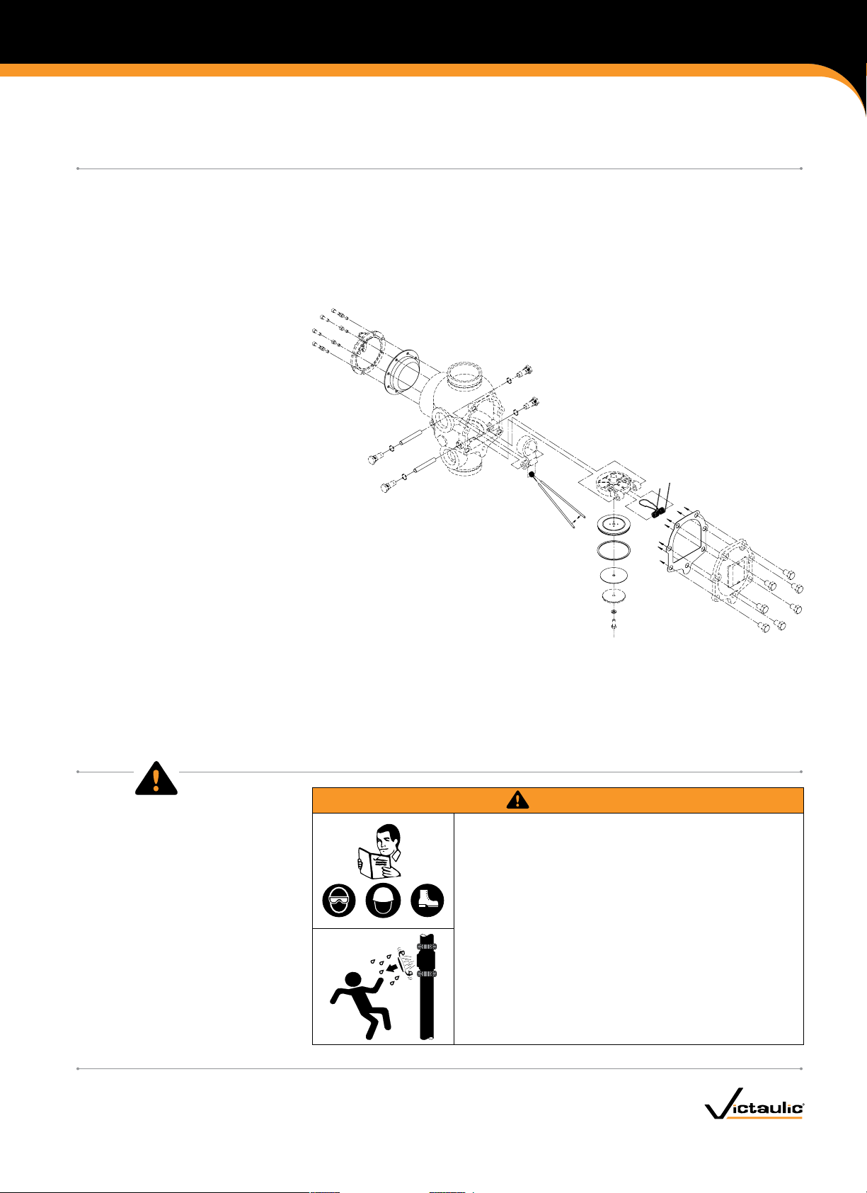
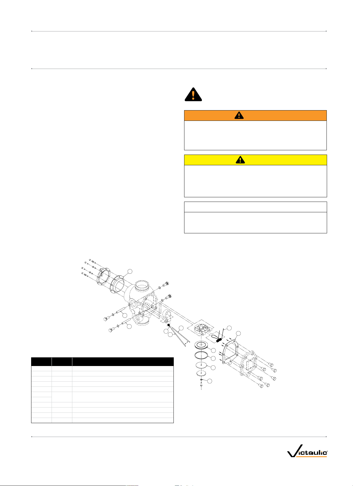
CONTENTS OF REBUILD KIT
11
6
5
Internal Components of the Valve
Item Qty. Description
1
2
3*
4
5
6
7
8
9
10
11
* Item #3 is not applicable for 1 ½ – 2-inch/48.3 – 60.3-mm valve sizes.
Clapper Seal
1
1
Seal Ring
Seal Washer
1
1
Bolt Seal
Clapper Shaft
1
Latch Shaf t
1
Clapper Spring
1
Latch Spring
1
Latch Spring Insertion Tool
2
Cover Plate Gasket
1
Diaphragm
1
9
8
9
4
7
10
1
2
3
www.victaulic.com
VICTAULIC IS A REGISTERED TRADEMARK OF VICTAULIC COMPANY. © 2010 VICTAULIC COMPANY. ALL RIGHTS RESERVED. PRINTED IN THE USA.
REV_A
I-NXT.RBKIT_1
Page 3
REBUILD KIT INSTRUCTIONS
5-Year Rebuild Kit Instructions for
FireLock NXT
SERIES 768 AND 769
REMOVING THE SYSTEM FROM SERVICE
™
Valves
WARNING
• Depressurize and drain the piping system
before attempting to remove the cover plate
from the valve.
Failure to follow this instruction could result
in serious personal injury and/or property
damage.
CAUTION
• Any activities that require taking the
valve out of service may eliminate the fire
protection provided.
• Before servicing or testing the system,
notify the authority having jurisdiction.
• Consideration of a fire patrol should be
given in the affected areas.
Failure to follow these instructions could
result in serious personal injury and/or
property damage.
I-NXT.RBKIT
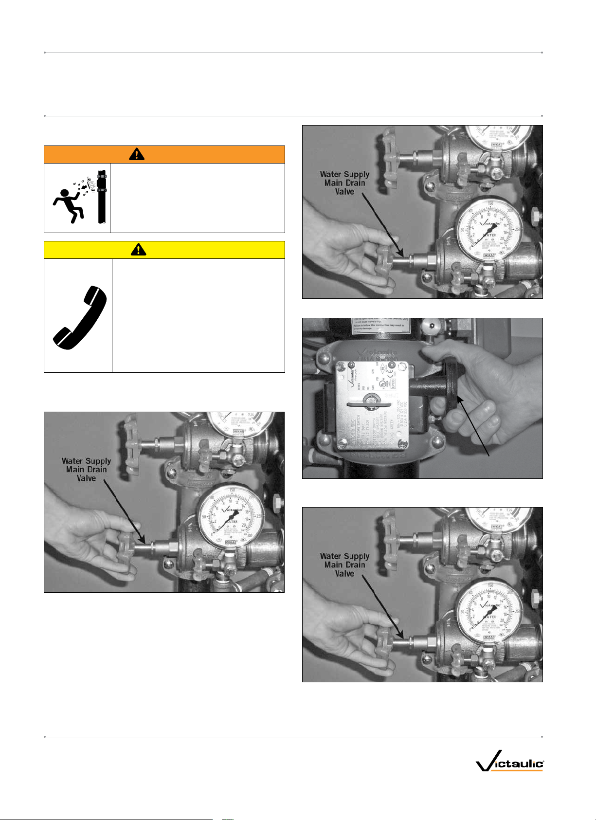
3. Close the water supply main drain valve.
1. Notify the authority having jurisdiction, remote station alarm
monitors, and those in the af fected area that the system is being
taken out of service.
2. Open the water supply main drain valve fully to flush the water
supply of any contaminants.
Water Supply Main
Control Valve
4. Close the water supply main control valve to take the system out of
service.
5. Open the water supply main drain valve.
6. Confirm that water is not flowing from the water supply main drain
valve.
www.victaulic.com
VICTAULIC IS A REGISTERED TRADEMARK OF VICTAULIC COMPANY. © 2010 VICTAULIC COMPANY. ALL RIGHTS RESERVED. PRINTED IN THE USA.
I-NXT.RBKIT_2
REV_A
Page 4
5-Year Rebuild Kit Instructions for
FireLock NXT
SERIES 768 AND 769
™
Valves
I-NXT.RBKITREBUILD KIT INSTRUCTIONS
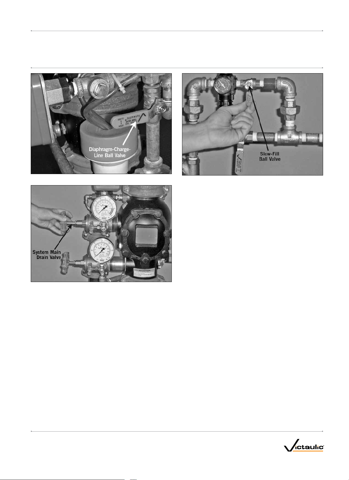
7. Close the diaphragm-charge-line ball valve.
8. Open the system main drain valve to drain any water that has
accumulated and to release system air pressure.
NOTE: If the system has operated, open the remote system test valve
(inspector’s test connection) and any auxiliary drain valves.
9. Close the slow-fill ball valve on the Air Maintenance Trim Assembly
(AMTA).
10. PUSH DOWN ON THE AUTO DRAIN SCREW TO REMOVE
PRESSURE IN THE DIAPHRAGM CHARGE LINE.
www.victaulic.com
VICTAULIC IS A REGISTERED TRADEMARK OF VICTAULIC COMPANY. © 2010 VICTAULIC COMPANY. ALL RIGHTS RESERVED. PRINTED IN THE USA.
REV_A
I-NXT.RBKIT_3
Page 5

REBUILD KIT INSTRUCTIONS
5-Year Rebuild Kit Instructions for
FireLock NXT
SERIES 768 AND 769
INSTRUCTIONS FOR REPLACING INTERNAL
COMPONENTS OF THE VALVE
(ITEMS 1 - 10 ON PAGE 1)
™
Valves
WARNING
• Make sure the valve is depressurized
and drained completely before the
cover plate bolts are removed.
The cover plate could blow off if the
cover plate bolts are removed while the
valve is pressurized, resulting in serious
personal injury and/or property damage.
I-NXT.RBKIT
4. Remove the clapper shaft bushings from the valve body.
1. After all pressure is released from the system, loosen the cover
plate bolts slowly. NOTE: DO NOT remove any cover plate bolts
until all cover plate bolts are loosened.
2. Remove all cover plate bolts, along with the cover plate and
cover plate gasket. Discard the old cover plate gasket. NOTE:
The 1 ½-inch/48.3-mm and 2-inch/60.3-mm valve sizes contain
washers under the heads of the cover plate bolts. Keep these
washers for re-installation.
3. Push the latch back (toward the diaphragm).
5. Remove the clapper shaft. NOTE: As the shaft is being removed,
the clapper spring will drop out of position. Discard the clapper
spring.
6. Remove the clapper from the valve body.
www.victaulic.com
VICTAULIC IS A REGISTERED TRADEMARK OF VICTAULIC COMPANY. © 2010 VICTAULIC COMPANY. ALL RIGHTS RESERVED. PRINTED IN THE USA.
I-NXT.RBKIT_4
REV_A
Page 6

5-Year Rebuild Kit Instructions for
FireLock NXT
SERIES 768 AND 769
7. Remove the latch-shaft retaining plugs from the valve body.
™
Valves
I-NXT.RBKITREBUILD KIT INSTRUCTIONS
WARNING
• DO NOT allow the latch to drop onto the valve-body seat ring.
Failure to follow this instruction will damage the valve-body seat
ring and cause improper valve operation, resulting in serious
personal injury and/or property damage.
8. Remove the latch shaft. NOTE: As the latch shaft is being
removed, the latch and latch spring will drop out of position. BE
PREPARED TO SUPPORT THE LATCH AND LATCH SPRING
DURING REMOVAL OF THE LATCH SHAFT. DO NOT ALLOW
THE LATCH TO DROP ONTO THE VALVE-BODY SEAT RING.
Discard the latch shaft and latch spring. Save the latch for
re-installation.
This Side Must
Face Toward
Outside of Valve
9. Insert the new latch shaft (supplied with the kit) through the
valve body and into the first arm of the shaft. MAKE SURE
THE RECESSED SIDE OF THE LATCH FACES TOWARD THE
OUTSIDE OF THE VALVE BODY, AS SHOWN ABOVE.
This Side Must
Face Toward
Diaphragm
WARNING
• Make sure the latch is re-installed in the correct orientation.
Failure to re-install the latch in the correct orientation could
cause improper valve operation, resulting in serious personal
injury and/or property damage.
www.victaulic.com
VICTAULIC IS A REGISTERED TRADEMARK OF VICTAULIC COMPANY. © 2010 VICTAULIC COMPANY. ALL RIGHTS RESERVED. PRINTED IN THE USA.
REV_A
10. Place a spring insert tool (supplied with the kit) onto each arm of
the new latch spring (supplied with the kit). Using the spring insert
tool to close the latch spring arms together slightly, install the latch
spring onto the latch shaft, as shown above.
11. Continue to pass the latch shaft through the other arm of the latch
and valve body.
I-NXT.RBKIT_5
Page 7

REBUILD KIT INSTRUCTIONS
5-Year Rebuild Kit Instructions for
FireLock NXT
SERIES 768 AND 769
12. REMOVE THE SPRING INSERT TOOLS FROM THE ARMS OF
THE LATCH SPRING.
™
Valves
I-NXT.RBKIT
15. Insert the clapper shaft halfway into the valve body.
16. Install the clapper spring onto the clapper shaft. Make sure the
loop of the clapper spring is facing toward the clapper, as shown
above.
17. Finish inserting the clapper shaft through the clapper arm and
valve body.
13. Apply a thin coat of Victaulic lubricant or silicone lubricant to the
o-ring on each latch-shaft retaining plug. Install the latch-shaft
retaining plugs into the valve body.
13a. Tighten the latch-shaft retaining plugs until metal-to-metal contact
occurs with the valve body.
18. Apply a thin coat of Victaulic lubricant or silicone lubricant to the
o-ring on each clapper shaft bushing. Install the clapper shaft
bushings into the valve body until hand-tight.
19. Tighten the clapper shaft bushings until metal-to-metal contact
occurs with the valve body.
14. Place the new clapper assembly onto the valve-body seat ring.
Make sure the holes in the clapper arms align with the holes in the
valve body.
www.victaulic.com
VICTAULIC IS A REGISTERED TRADEMARK OF VICTAULIC COMPANY. © 2010 VICTAULIC COMPANY. ALL RIGHTS RESERVED. PRINTED IN THE USA.
I-NXT.RBKIT_6
REV_A
Page 8

5-Year Rebuild Kit Instructions for
FireLock NXT
SERIES 768 AND 769
™
Valves
I-NXT.RBKITREBUILD KIT INSTRUCTIONS
20. Check the clapper for freedom of movement.
21. Rotate the clapper out of the valve body. Remove the seal
assembly bolt/bolt seal from the clapper seal, as shown above.
Save the seal assembly bolt for re-installation. Discard the bolt
seal.
23. Pry the edge of the old seal washer from inside the clapper seal.
Remove and discard the seal washer.
24. Pry the old clapper seal, along with the seal ring, out of the
clapper. Discard the clapper seal and seal ring.
25. Install the new clapper seal assembly (supplied with the kit) into
the clapper carefully. Make sure the seal ring snaps into the
22. Remove the seal-retaining ring. Save the seal-retaining ring for
re-installation.
www.victaulic.com
VICTAULIC IS A REGISTERED TRADEMARK OF VICTAULIC COMPANY. © 2010 VICTAULIC COMPANY. ALL RIGHTS RESERVED. PRINTED IN THE USA.
REV_A
clapper completely.
I-NXT.RBKIT_7
Page 9

5-Year Rebuild Kit Instructions for
FireLock NXT
SERIES 768 AND 769
26. Install the new bolt seal (supplied with the kit) onto the sealassembly bolt.
™
Valves
I-NXT.RBKITREBUILD KIT INSTRUCTIONS
REQUIRED SEAL-ASSEMBLY BOLT/BOLT SEAL TORQUES
Nominal Size
inches
1 ½
2
2 ½
76.1 mm
3
4
165.1 mm
6
8
Size Torque
Actual
Outside D iameter
inches
mm
1.900 40
48.3 5
2.375 40
60.3 5
2.875 90
73.0 10
3.000 90
76.1 10
3.500 90
88.9 10
4.500 110
114.3 12
6.500 160
165.1 18
6.625 160
168.3 18
8.625 160
219.1 18
inch-lbs
N•m
27. Place the seal-retaining ring onto the seal washer of the clapper
seal. Install the seal-assembly bolt/bolt seal through the sealretaining ring and clapper.
29. Align the holes of the new cover plate gasket (provided with the
kit) with the holes in the cover plate.
28. Tighten the seal-assembly bolt/bolt seal to the torque value listed
in the table on this page to ensure a proper seal.
30. Insert one cover plate bolt through the cover plate and cover plate
gasket to ease alignment. NOTE: For 1 ½-inch/48.3-mm and
2-inch/60.3-mm valve sizes, a washer must be re-installed under
the head of each cover plate bolt.
www.victaulic.com
VICTAULIC IS A REGISTERED TRADEMARK OF VICTAULIC COMPANY. © 2010 VICTAULIC COMPANY. ALL RIGHTS RESERVED. PRINTED IN THE USA.
I-NXT.RBKIT_8
REV_A
Page 10

5-Year Rebuild Kit Instructions for
FireLock NXT
SERIES 768 AND 769
™
Valves
I-NXT.RBKITREBUILD KIT INSTRUCTIONS
CAUTION
• DO NOT over-tighten the cover plate bolts.
Failure to follow this instruction could cause damage to the
cover plate gasket, resulting in valve leakage.
31. Align the cover plate/cover plate gasket to the valve. Make sure the
clapper spring’s arms are rotated to their installed position. Tighten
all cover plate bolts into the cover plate/valve body.
32. Torque all cover plate bolts in an even, crossing pattern. Refer
to the “Required Cover Plate Bolt Torques” table below for the
required torque values. DO NOT over-tighten the cover plate bolts.
INSTRUCTIONS FOR REPLACING THE
DIAPHRAGM (ITEM 11 ON PAGE 1)
WARNING
• Make sure the valve is depressurized and
drained before attempting to remove any trim
from the valve.
Failure to depressurize and drain the valve before
removing any trim from the valve could cause
serious personal injury and/or property damage.
If the system is in service, follow the “Removing the System from
Service” section.
1. Break the unions that connect the trim to the diaphragm cover.
Refer to the applicable trim drawing for details.
Required Cover Plate Bolt Torques
Size Torque
Nominal Size
inches
1 ½
2
2 ½
76.1 mm
3
4
165.1 mm
6
8
Outside D iameter
Actual
inches
mm
1.900 30
48.3 41
2.375 30
60.3 41
2.875 60
73.0 81
3.000 60
76.1 81
3.500 60
88.9 81
4.500 100
114.3 136
6.500 115
165.1 156
6.625 115
168.3 156
8.625 100
219.1 136
ft-lbs
N•m
2. Remove the cap screws from the diaphragm cover, and pull the
diaphragm cover/trim off the valve.
3. Remove the old diaphragm from the valve body. Discard the
diaphragm.
www.victaulic.com
VICTAULIC IS A REGISTERED TRADEMARK OF VICTAULIC COMPANY. © 2010 VICTAULIC COMPANY. ALL RIGHTS RESERVED. PRINTED IN THE USA.
REV_A
I-NXT.RBKIT_9
Page 11

5-Year Rebuild Kit Instructions for
FireLock NXT
SERIES 768 AND 769
4. Clean the back of the valve body to remove any debris that may
interfere with proper diaphragm seating.
™
Valves
I-NXT.RBKITREBUILD KIT INSTRUCTIONS
5. Install the new diaphragm (provided with the kit) by aligning the
holes in the diaphragm with the holes in the valve body. Be careful
not to damage the diaphragm during installation.
4a. Clean the inside of the diaphragm cover to remove any foreign
material.
6. Align the holes of the diaphragm cover with the holes in the
CAUTION
• Use caution when installing a new diaphragm into the valve
body.
Failure to follow this instruction could cause damage to the
diaphragm, resulting in improper valve operation and valve
leakage.
For complete contact information, visit w ww.victaulic.com
I-NXT.RBKIT 6071 REV A UPDATED 03/2010 ZNXT5RBKIT
VICTAULIC IS A REGISTERED TRADEMARK OF VICTAULIC COMPANY. © 2010 VICTAULIC COMPANY. ALL RIGHTS RESERVED. PRINTED IN THE USA.
I-NXT.RBKIT
diaphragm/valve body. Tighten all cap screws into the diaphragm
cover/valve body.
7. Re-attach the trim at the unions that were loosened in step 1.
Refer to the applicable trim drawing for details. MAKE SURE
ALL UNIONS THAT WERE LOOSENED TO PERMIT ACCESS
TO THE DIAPHRAGM COVER ARE RE-TIGHTENED BEFORE
ATTEMPTING TO PLACE THE SYSTEM BACK IN SERVICE.
8. Place the system back in service by following the “Placing
the System in Service” section in the applicable installation,
maintenance, and testing manual for the valve.
 Loading...