

Page 1
Victaulic® Grooved End Fittings
07.01
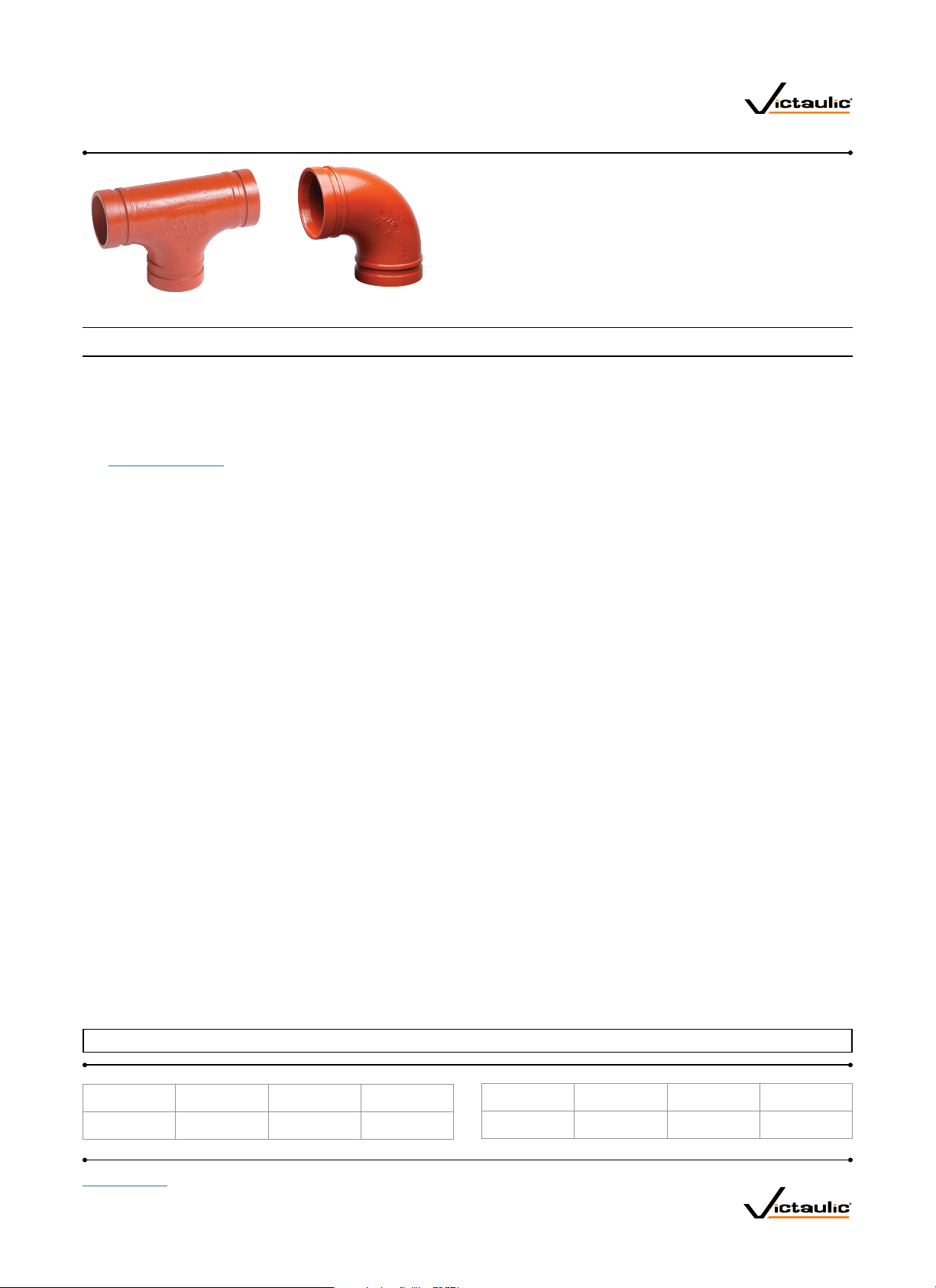
No. 20 Tee No. 10 Elbow
1.0 PRODUCT DESCRIPTION
Available Sizes
• ¾ – 60"/DN20 – DN1500
Maximum Working Pressure
• Pressure ratings for Victaulic standard fittings conform to the ratings of Victaulic Style 177N couplings (refer to
publication 06.24 for more information).
Application
• Connects pipe, provides change in direction and adapts sizes or components
• Supplied with Victaulic OGS grooves
• Exclusively for use with Victaulic couplings, valves, accessories and pipe which feature ends formed with the
Victaulic OGS groove profile
Pipe Materials
• Carbon steel or stainless steel
NOTE
• These fittings are not intended for use with Victaulic plain end couplings. Intended for use only in grooved piping systems. When connecting wafer or lug type
butter fly valves directly to Victaulic fittings using St yle 741 or Style 743 flange adapters, be sure to check disc clearance dimensions with I.D. dimension of
fitting.
ALWAYS REFER TO ANY NOTIFICATIONS AT THE END OF THIS DOCUMENT REGARDING PRODUCT INSTALLATION, MAINTENANCE OR SUPPORT.
System No. Location
Submitted By Date
Spec Section Paragraph
Approved Date
victaulic.com
07.01 1449 R ev AF Updated 08 / 2017 © 2017 Victaulic Company. All rights reserved.
1
Page 2

victaulic.com
2.0 CERTIFICATION/LISTINGS
NOTES
• When supplied as “hot dip galvanized” the following fittings are UL Classified in accordance with ANSI/NSF 61 and for use on cold + 86º F/+30ºC potable water
service and ANSI/NSF 372: No. 10 90 º Elbow, No. 11 45º Elbow, No. 12 22 ½º Elbow, No. 13 11 ¼º Elbow, No. 100 90º Long Radius Elbow, No. 110 45º Long
Radius Elbow, No. 20 Tee, No. 25 Tee with Grooved Branch, No. 30 45º Lateral, No. 60 Cap, No. 50 Concentric Reducers, No. 51 Eccentric Reducers.
• The following Victaulic fittings are VdS approved: No.10 90º Elbow, No.11 45º Elbow, No.20 Tee and No.60 Cap.
• The following Victaulic fittings are LPCB approved: No.10 90º Elbow, No.11 45º Elbow, No.12 22 ½ Elbow, No.13 11 ¼º Elbow, No.30 45º L ateral, No.30-R
Reducing Lateral, No.100 Long Radius Elbow, No.110 Long Radius Elbow, No.20 Tee, No.35 Cross, No.60 Cap, No.25 Reducing Tee, No.33 True Wye, No.50
Concentric Reducer, No.51 Eccentric Reducer and No.29M Tee with Threaded Branch.
• The following Victaulic fittings are FM approved: No.10 90º Elbow, No.11 45º Elbow, No.12 22 ½ Elbow, No.13 11 ¼º Elbow, No.30 45º L ateral, No.100 Long
Radius Elbow, No.20 Tee, No.35 Cross, No.60 C ap, No.25 Reducing Tee and No.50 Concentric Reducer.
3.0 SPECIFICATIONS - MATERIAL
Fitting: (specify choice)
Standard: Ductile iron conforming to ASTM A536, Grade 65-45-12.
Optional: Segmentally welded steel as shown under nipples
Nipples: (specify choice)
¾ – 4"/DN20 – DN100: Carbon steel, Schedule 40, conforming to ASTM A53, Type F
5 – 6"/DN125 – DN150: Carbon steel, Schedule 40, conforming to ASTM A53, Type E or S, Gr. B
8 – 12"/DN200 – DN300: Carbon steel, Schedule 30 or 40, conforming to ASTM A53, Type E or S, Gr. B
Flanged Adapter Nipples: (specify choice)
Class 125 Flange: Cast iron conforming to ANSI B16.1
Class 150 Flange: Carbon steel conforming to ANSI B16.5, raised or flat face
Class 300 Flange: Carbon steel conforming to ANSI B16.5, raised or flat face
Fitting Coating: (specify choice)
Standard: Orange enamel
Optional: Hot dip galvanized and others. Some fittings supplied electroplated as standard – see product
specifications
Flanged Adapter Nipple Coating: (specify choice)
Standard: None (Unfinished)
Optional: Orange enamel, hot dip galvanized and others
07.01 1449 R ev AF Updated 08 / 2017 © 2017 Victaulic Company. All rights reserved.
victaulic.com
3
Page 3

victaulic.com
4.15 DIMENSIONS
Concentric/Eccentric Reducer
No. 50 Concentric
No. 51 Eccentric
E
to E
No. 50 No. 51
Size
Nominal E to E
inches
DN
x
x
x
x
x
x
x
¾
DN20
1
DN25
¾
DN20
1
DN25
1¼
DN32
¾
DN20
1
DN25
1¼
DN32
1½
DN40
¾
DN20
1
DN25
1¼
DN32
1½
DN40
2
DN50
¾
DN20
1
DN25
1¼
DN32
1½
DN40
2
DN50
2½
DN65
3
DN80
1
DN25
1¼
DN32
1½
DN40
2
DN50
2½
3
DN80
3½
DN90
4
DN100
E to E
Fabricated Steel
No. 50 Concentric
Reducer
Approx.
Weight
(Each) E to E
inches
mm
+
+
+
2.50
64
2.50
64
2.50
64
2.50
64
2.50
64
2.50
64
+
2.50
64
3.50
89
2.50
64
2.50
64
+
2.50
64
2.50
64
2.50
64
2.50
64
2.50
64
2.50
64
2.50
64
3.00
76
lb
kg
1.9
0.9
1.9
0.9
1.4
0.6
0.8
0.4
1.0
0.5
0.9
0.3
0.7
0.3
1.2
0.5
1.0
0.5
1.3
0.6
1.1
0.5
3.3
1.5
3.6
1.6
3.9
1.8
1.5
0.7
1.3
0.6
1.4
0.6
5.1
2.3
1.6
0.7
1.8
0.8
2.1
1.0
2.0
0.9
3.0
1.4
E to E
No. 50
E to E
Fabricated Steel
No. 51
No . 51
Eccentric Reducer
inches
mm
— —
— —
— —
8.50 (sw)
216
— —
9.00 (sw)
229
9.00 (sw)
229
9.00 (sw)
229
3.50
89
+
9.50
241
3.50
89
9.50 (sw)
241
3.50
89
+
9.50 (sw)
241
+
9.50 (sw)
241
3.50
89
3.50
89
— —
9.50 (sw)
241
13.00 (sw)
330
Approx.
Weight
(Each)
lb
kg
4.5
2.0
2.0
0.9
2.3
1.0
4.6
2.1
1.1
0.5
3.3
1.5
3.5
1.6
1.4
0.6
3.7
1.7
4.3
2.0
4.5
2.0
4.8
2.2
4.8
2.2
5.1
2.3
6.0
2.7
7.0
3.2
7.0
3.2
6.5
2.9
E
to E
No. 50 No. 51
Size
Nominal E to E
inches
DN
1¼
DN32
1½
DN40
2
DN50
2½
3
DN80
3½
DN90
5
6
DN150
8
DN200
2
x
DN50
2½
3
DN80
4
DN100
1
x
DN25
1½
DN40
2
DN50
2 ½ 4.00
3
DN80
4
DN100
5 4.00
2½ 16.00
x
3
DN80
4
DN100
5
6
DN150
E to E
Fabricated Steel
No. 50 Concentric
Reducer
Approx.
Weight
(Each) E to E
inches
mm
+
3.00 (sw)
76
3.00
76
3.00
76
3.00
76
3.00
76
11.00 (sw)
279
4.00
102
4.00
102
3.50
89
4.00
102
+
4.00
102
102
4.00
102
4.00
102
102
406
5.00
127
5.00
127
5.00
127
5.00
127
lb
kg
4.6
2.1
2.6
1.2
2.4
1.1
2.7
1.2
3.2
1.4
2.9
1.3
9.0
4.1
4.3
2.0
5.5
2.5
4.3
1.9
5.0
2.3
5.5
2.5
6.6
3.0
6.4
2.9
6.4
2.9
6.5
2.9
6.4
2.9
7.9
3.6
9.3
4.2
10.4
4.8
11.6
5.2
11.9
5.4
E to E
No. 50
E to E
Fabricated Steel
No. 51
No . 51
Eccentric Reducer
inches
mm
— —
10.00 (sw)
254
4.00
102
4.00
102
4.00
102
10.00 (sw)
254
11.00 (sw)
279
11.00 (sw)
279
11.00 (sw)
279
5.00
127
11.50 (sw)
292
+ +
11.50 (sw)
292
11.50 (sw)
292
5.50
140
5.50
140
5.50
140
12.00 (sw)
305
12.00 (sw)
305
12.00 (sw)
305
12.00 (sw)
305
6.00
152
Approx.
Weight
(Each)
lb
kg
8.1
3.7
3.3
1.5
3.4
1.5
3.5
1.6
8.0
3.6
5.2
2.4
10.8
4.9
11.1
5.0
12.0
5.4
14.5
6.6
14.5
6.6
14.2
6.4
15.0
6.8
17.0
7.7
17.0
7.7
26.1
11.8
22.0
10.0
23.0
10.4
23.0
10.4
24.0
10.9
07.01 1449 R ev AF Updated 08 / 2017 © 2017 Victaulic Company. All rights reserved.
victaulic.com
21
Page 4

victaulic.com
4.15 DIMENSIONS (Continued)
Concentric/Eccentric Reducer
No. 50 Concentric
No. 51 Eccentric
E
to E
No. 50 No. 51
Size
E to E
Fabricated Steel
No. 50
No. 50 Concentric
Reducer
E to E
Fabricated Steel
No. 51
No . 51
Eccentric Reducer
Approx.
Weight
Nominal E to E
inches
DN
10
x
DN250
DN100
DN150
DN200
12
x
DN300
DN100
DN150
DN200
10
DN250
2
14
x
DN350
DN150
DN200
10
DN250
12
DN300
2
16
x
DN400
DN200
10
DN250
12
DN300
14
DN350
2
18
DN450
10
x
DN250
12
DN300
14
DN350
16
DN400
2
For 14"/DN350 and larger roll grooved systems, Victaulic of fers the
Advanced Groove System (AGS). For pricing and availability of cut groove
fittings in this size, contact your nearest Victaulic sales representative.
inches
mm
4
6.00
152
5
6
+
6.00
152
8
6.00
152
4
6
+
7.00
178
8
7.00
178
7.00
178
6
13.00
330
8
13.00
330
13.00
330
13.00
330
8
14.00
356
14.00
356
14.00
356
14.00
356
15.00
381
15.00
381
15.00
381
15.00
381
(Each) E to E
lb
kg
19.7
8.9
33.0
15.0
20.0
9.1
22.0
10.0
44.0
20.0
24.6
11.2
52.0
23.6
39.0
17.7
65.0
29.5
65.0
29.5
66.0
29.9
68.0
30.8
73.0
33.1
73.0
33.1
73.0
33.1
73.0
33.1
91.0
41.3
91.0
41.3
91.0
41.3
91.0
41.3
inches
mm
13.00 (sw)
330
+
13.00 (sw)
330
7.00
178
14.00 (sw)
356
14.00 (sw)
356
14.00 (sw)
356
14.00 (sw)
356
13.00
330
13.00
330
13.00
330
13.00
330
14.00
355
14.00
355
14.00
355
14.00
355
15.00
381
15.00
381
15.00
381
15.00
381
E to E
Approx.
Weight
(Each)
kg
32.0
14.5
34.6
15.7
36.9
16.7
21.6
9.8
48.0
21.8
50.0
22.7
53.5
24.3
57.0
25.9
60.0
27.2
60.0
27.2
65.0
29.5
66.0
29.9
73.0
33.1
73.0
33.1
73.0
33.1
73.0
33.1
91.0
41.3
91.0
41.3
91.0
41.3
91.0
41.3
lb
E
to E
No. 50 No. 51
Size
Nominal E to E
inches
DN
2
20
DN500
10
x
DN250
12
DN300
14
DN350
16
DN400
18
DN450
2
24
DN600
10
x
DN250
12
DN300
14
DN350
16
DN400
18
DN450
20
DN500
14 – 60
E to E
Fabricated Steel
No. 50 Concentric
Reducer
Approx.
Weight
(Each) E to E
inches
mm
20.00
508
20.00
508
20.00
508
20.00
508
20.00
508
20.00
508
20.00
508
20.00
508
20.00
508
20.00
508
20.00
508
lb
kg
110.0
49.9
120.0
54.4
149.0
67.9
120.0
54.4
136.0
61.7
142.0
64.4
150.0
68.0
162.0
73.5
162.0
73.5
162.0
73.5
151.0
68.5
E to E
No. 50
Eccentric Reducer
inches
mm
20.00
508
20.00
508
20.00
508
20.00
508
20.00
508
20.00
508
20.00
508
20.00
508
20.00
508
20.00
508
20.00
508
E to E
Fabricated Steel
No. 51
No . 51
Approx.
Weight
(Each)
lb
kg
177.0
80.3
120.0
54.4
149.0
67.9
120.0
54.4
136.0
61.7
142.0
64.4
150.0
68.0
162.0
73.5
162.0
73.5
162.0
73.5
190.0
86.2
For AGS fitting information, see publication 20.05
DN350 – DN1500
2
For 14"/DN350 and larger roll grooved systems, Victaulic of fers the
Advanced Groove System (AGS). For pricing and availability of cut groove
fittings in this size, contact your nearest Victaulic sales representative.
(s) = Carbon Steel Direct Roll Groove (OGS)
(sw) = Carbon Steel Segmentally Welded
+ Contact Victaulic for details.
NOTES
• Available with male threaded small end No. 52.
• Cast fitting available for JIS size. Contact Victaulic for details.
• Steel eccentric reducers available through 30”/DN750, contact Victaulic
for dimensions.
• All fittings are ductile iron unless otherwise noted with an (sw) or (s).
07.01 1449 R ev AF Updated 08 / 2017 © 2017 Victaulic Company. All rights reserved.
victaulic.com
22
 Loading...