

Vicruns VD120-2S-2.2GB, VD120-2T-1.5GB, VD120-2T-0.4GB, VD120-2T-0.7GB, VD120-2T-2.2GB Series Manual
...
Preface
Thank you for purchasing VD120 Series Inverters!
Unpacking and Inspection:
Every inverter has been inspected rigorously before shipping.
Please confirm carefully when unpacking the packing carton:
● Check if any damage signs of the product and its package.
● Check if the model and inverter rated values on the nameplate are the same as stated on your order
and user manual.
● The box contains the inverter, manufacturer certificate, user manual.
If the product is damaged during transportation, or there is any omission or damage, please contact
our company or your local supplier immediately.


Contents
Chapter 1 Safety and Precautions ............ ............ ............ ............ .... - 1 -
1.1 Safety Precautions...... ............ ............ ...................... .......... - 1 -
Chapter 2 Product Information .. ...................... ............ ............ ....... - 3 -
2.1 Designation Rules ...... ............ ............ ...................... .......... - 3 -
2.2 Nameplate...... ............ ...................... ............ ............ ..... - 3 -
2.3 Inverter Series ............ ............ ............ ............ ................. - 3 -
2.4 Product Appearances and Installation Dimension .................... ............ .... - 4 -
2.5 Recommended Brake Resistor Selection Table ........ ............ ............ ...... - 7 -
2.6 Warranty Introduction.............. ...................... ............ ............ - 7 -
Chapter 3 Mechanical and Electrical Installation ........ ............ .................... - 8 -
3.1 Standard Wiring Diagram .. ............ ............ ...................... ........ - 8 -
3.2 Main Circuit Terminals ...................... .................................. ... - 8 -
3.3 Control Circuit Terminal .... ............ ............ ...................... ........ - 9 -
Chapter 4 Operation and Display .................... ............ ............ ........ - 12 -
4.1 Introduction to Operation and Display Interface...... ............ ............ ....... - 12 -
Chapter 5 Function Parameter Table ................ ...................... ........... - 14 -
Chapter 6 Parameter Description .... ............ ...................... ............ .. - 64 -
F0 Basic Function.. ............ ............ ............ ............ ............... - 64 -
F1 Start/Stop Control Group .... ............ ............ ............ ................ - 71 -
F2 Motor 1 Parameter ...... ............ ............ .......... ............ ......... - 77 -
F3 Motor 1 Vector Control Parameter ........ ............ ............ ............ .... - 79 -
F4 Motor 1 V/F Control Parameter .............. ............ ............ ............ . - 82 -
F5 Input Terminal Group ............ ............ ............ .......................- 86 -
F6 Output Terminal Function Group............ ............ ...................... .... - 98 -
F7 Keyboard and Display Function Group ............ ............ ............ ....... - 103 -
F8 Protection Parameters ............................ ............ ............ ..... - 107 -
F9 Fault Record and Setting Parameter Group .. ............ ...................... ... - 110 -
FA Process PID Parameter Group .......................... ............ ............ - 114 -
Fb Enhance Function Group.. ...................... ............ ............ ....... - 118 -
Fd MODBUS Communication Parameter Group ........ ...................... ........ - 132 -
FF User Parameters Group.................... ............ ............ ............ - 133 -
FP Factory Parameter Group .. ............ ............ ...................... ...... - 135 -
A0 Motor 1 Torque Control Parameter Group...................... ............ ....... - 135 -
AI Optimize Control Parameter Group .................. ............ ............ ..... - 138 -
b0 User Customize Function Code............ ............ ............ ............ .. - 141 -
b1 Virtual IO Parameter Group ...................... ............ ............ ....... - 142 -
b2 AI Curve Setting Parameter Group .............................. ............ ..... - 146 -
b3 AIAO Correction Parameter Group .............................. ............ ..... - 148 -
U0 Basic Monitoring Parameters Group .................. ............ ............ ... - 149 -
Chapter 7 EMC Guide ........................ ............ ............ ............ - 151 -
7.1 Definition ................................ ............ ............ ............ - 151 -
7.2 EMC Standard Introduction ........ ............ ............ ............ ......... - 151 -
7.3 EMC Guide .............................. ............ ............ ............ - 151 -
Chapter 8 Fault Shooting and Solutions .................. ............ ............ ... - 153 -
8.1 Fault Alarm and Countermeasures .................. ............ ............ .... - 153 -
8.2 Common Faults and Solutions .................... ............ .................. - 157 -

Chapter 9 Communication Protocol .................. ............ ............ ....... - 158 -
9.1 About Protocol .......... ............ ............ ............ ............ ..... - 158 -
9.2 Application Methods........ ...................... ............ ............ ..... - 158 -
9.3 Bus Structure ........ ............ ............ ............ .................... - 158 -
9.4 Protocol Description............ ............ ............ ...................... . - 158 -
9.5 Communication Frame Structure ........................ ............ ............ - 158 -
9.6 Command Code and Communication Data Description ................ ............. - 159 -
Fd MODBUS Communication .................................. ............ ........ - 167 -
VD120 Series Inverter User Manual
Safety and Precautions
Chapter 1 Safety and Precautions
1.1 Safety Precautions
1.1.1 At Wiring
● Wiring must be performed only by qualified personnel under instructions described in this
manual. Failure to comply may result in unexpected accidents.
● A circuit breaker must be used to isolate the power supply and inverter. Failure to comply may
result in a fire.
● Ensure that the power supply is cut off before wiring. Failure to comply may result in electric
shock.
● Connect inverter to ground properly by standard. Failure to comply may result in electric shock.
● Do not connect the input power with output terminals U, V, W, confirm the mark on terminal
before connection to avoid wrong wiring. Failure to comply can damage the inverter!
● Never connect the braking resistor between the DC bus terminals P+ and P-. Failure to comply
may result in a fire.
● The wire size of main circuit should conformed to standard, the wiring should comply with EMC
and local safety standard. Failure to comply may result in accidents.
● Use shielded cable for input output control circuit of analog and rapid speed pulse signal, and
ensure the shielding layer is reliably grounded.
1.1.2 Before Power-on:
● Check that the following requirements are met:
● The voltage class of the power supply is consistent with the rated voltage class of the AC drive.
● The input terminals (R, S, T) and output terminals (U, V, W) are properly connected.
● No short-circuit exists in the peripheral circuit.
● The wiring is secured.
● The external units of inverter and wires are configured under the manual instructed, all matched
circuit and wiring are correctly connected.
● Failure to comply will result in damage to inverter!
1.1.3 After Power-on
● Do not open the cover after inverter power-on to prevent electric shock.
● Do not touch or operate the inverter with wet hands. Failure to comply will result in electric shock.
● Do not touch any terminal of inverter after power-on, or drag connection cable. Failure to comply
will result in equipment damage or electric shock.
● Do not try to check or change the manufacturer parameter. Failure to comply may result in
malfunction or damage to inverter!
● Make sure the mechanical equipment is ready to start before inverter run with loading, make sure
related staff is in safety zone. Failure to comply will result in damage or personal hurt!
● Please pay attention to hiding accident which may result in personal hurt or property damage
while motor is run, if it is necessary to identify the motor parameter.
- 1 -
Safety and Precautions VD120 Series Inverter User Manual
1.1.4 During Operation
● Do not touch the cooling fan or braking resistor etc, otherwise may cause personal injury!
● Do not do inspection while inverter run, except for professional technician, otherwise may cause
inverter damaged or personal injury.
● Do not move inverter or the installed cabinet while it is run, keep external objects falling into the
device. Failure to comply will result in damage.
● Start/Stop inverter via terminal function or other control method, try not to start inverter via directly
power-on control method. Do not use contactor on inverter output terminal to control motor starting
or stop.
1.1.5 During Maintenance
● Do not repair and maintain the equipment if power is connected. Otherwise there will be danger
of electric shock!
● If the LED is still on light on control panel, it is Disabled to disassemble the body in order to avoid
electric shock.
● The inverter shall be repaired and maintained only by the qualified person who has received
professional training. Otherwise, it may cause personal injury or equipment damage.
● For all the standard equipped or optional accessories, must be dismounted or mounted while the
inverter power is disconnected.
- 2 -
VD120 Series Inverter User Manual Product Information
KW)
Chapter 2 Product Information
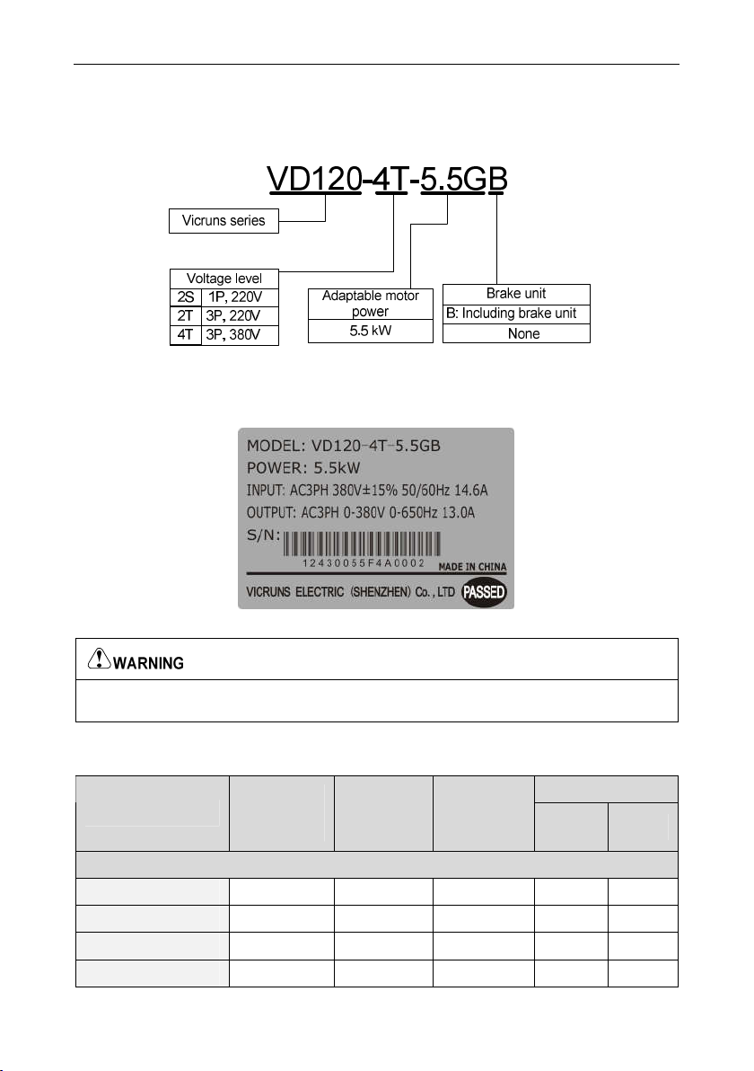
2.1 Designation Rules
Fig 2.1-1 Designation Rules
2.2 Nameplate
Fig 2.2-1 Namepate
● The bar code on inverter nameplate is the only code to recognize its identity, so the bar code is
the most important basis for the after sales service.
2.3 Inverter Series
Table 2-1 Product specifications and technical data
Model No.
Single-phase power supply: 220V,50/60Hz Range:-15%~20%
VD120-2S-0.4GB 1.0 5.4 2.3 0.4 0.5
VD120-2S-0.7GB 2.0 9.8 4.8 0.7 1
VD120-2S-1.5GB 3.0 14.0 7.0 1.5 2
VD120-2S-2.2GB 4.0 23.0 9.6 2.2 3
Power
Capacity
(KVA)
Rated Input
Current
(A)
Rated Output
Current
(A)
Adaptable Motor
(
(HP)
- 3 -
Product Information VD120 Series Inverter User Manual
KW)
A
B
Model No.
Three-phase power supply: 220V,50/60Hz Range: -15%~20%
VD120-2T-0.4GB 1.5 4.0 2.3 0.4 0.5
VD120-2T-0.7GB 3.0 6.0 4.8 0.8 1
VD120-2T-1.5GB 4.0 5.8 7.0 1.5 2
VD120-2T-2.2GB 5.9 10.5 9.6 2.2 3
VD120-2T-4.0GB 8.9 14.6 13.0 3.7 5
Three-phase power supply: 380V,50/60Hz Range: -15%~20%
VD120-4T-0.4GB 1.0 1.9 1.5 0.4 0.5
VD120-4T-0.7GB 1.5 4.0 2.5 0.8 1
VD120-4T-1.1GB 2.0 4.5 3.3 1.1 1.4
VD120-4T-1.5GB 3.0 5.0 3.8 1.5 2
VD120-4T-2.2GB 4.0 5.8 5.1 2.2 3
VD120-4T-3.0GB 5.5 9.2 8.0 3.0 4
VD120-4T-4.0GB 6.5 11.0 9.6 4.0 5.5
VD120-4T-5.5GB 8.9 14.6 13.0 5.5 7.5
VD120-4T-7.5GB 11.0 20.5 17.0 7.5 10
Power
Capacity
(KVA)
Rated Input
Current
(A)
Rated Output
Current
(A)
Adaptable Motor
(
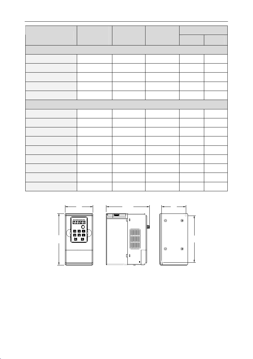
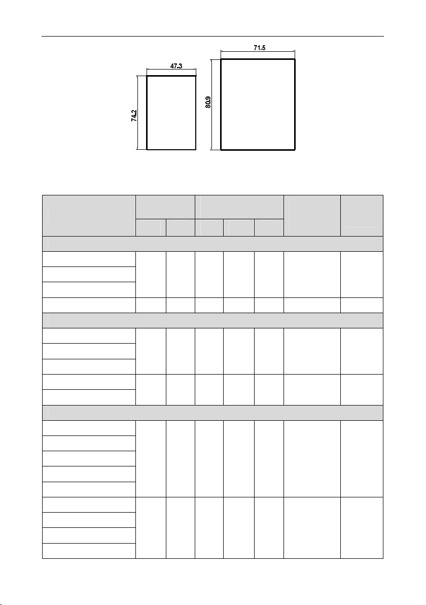
2.4 Product Appearances and Installation Dimension
W D
(HP)
H
Adaptive mode (wall mounting type, three phase 380V: 0.4kW-2.2kW /Single phase, three phase
220V: 0.4kW-1.5kW)
- 4 -

VD120 Series Inverter User Manual Product Information
W
A
B
H
D
Adaptive mode(wall mounting type, three phase 380V: 3kW-7.5kW/three phase 220V:
2.2kW~4.0kW/single phase 220V:2.2kW)
Fig 2.4-1 Schematic diagram of product appearance and installation dimensions
74
76.4
17.4 20.6
Schematic diagram of keyboard size
Schematic diagram of tray size
Fig 2.4-2 External lead keyboard and tray size (mm)
- 5 -
Product Information VD120 Series Inverter User Manual
Keyboard mounting hole size Keyboard mounting hole size
when without external lead when without external lead
Table 2-2 Physical Dimensions and Installation Hole(mm)
Mounting
Model
Single phase: 220V, 50/60Hz Range: -15%~20%
VD120-2S-0.4GB
VD120-2S-0.7GB
VD120-2S-1.5GB
VD120-2S-2.2GB 107.6 201 215 120 146
Three phase: 220V, 50/60Hz Range: -15%~20%
VD120-2T-0.4GB
VD120-2T-0.7GB
VD120-2T-1.5GB
VD120-2T-2.2GB
VD120-2T-4.0GB
Three phase: 380V, 50/60Hz Range:-15%~20%
VD120-4T-0.4GB
VD120-4T-0.7GB
VD120-4T-1.1GB
VD120-4T-1.5GB
VD120-4T-2.2GB
VD120-4T-3.0GB
VD120-4T-4.0GB
VD120-4T-5.5GB
VD120-4T-7.5GB
Hole (mm)
A B H W D
73 141 155 84 130
73 141 155 84 130
107.6 201 215 120 146
73 141 155 84 130
107.6 201 215 120 146
Physical Dimensions
(mm)
Dieameter of
Mounting
Hole (mm)
Weight
(kg)
4.5 1.4
4.5 2.4
4.5 1.4
4.5 2.4
4.5 1.4
4.5 2.4
- 6 -
VD120 Series Inverter User Manual Product Information
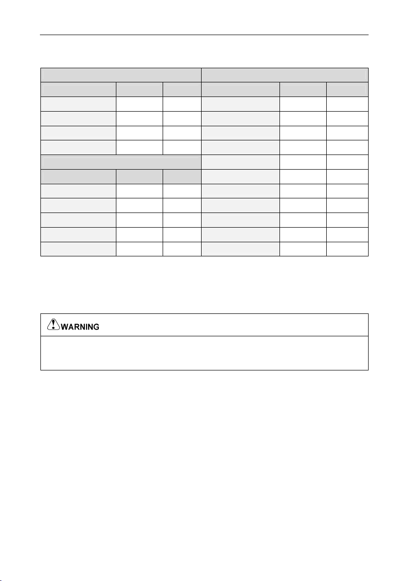
2.5 Recommended Brake Resistor Selection Table
Table 2-3 Recommended brake resistor selection table
Single phase, 220V Three phase, 380V
Model Resistor Power Model Resistor Power
VD120-2S-0.4GB ≥200Ω 80W VD120-4T-0.4GB ≥300Ω 150W
VD120-2S-0.7GB ≥150Ω 80W VD120-4T-0.7GB ≥300Ω 150W
VD120-2S-1.5GB ≥100Ω 100W VD120-4T-1.1GB ≥250Ω 150W
VD120-2S-2.2GB ≥70Ω 100W VD120-4T-1.5GB ≥220Ω 150W
Three phase, 220V VD120-4T-2.2GB 200Ω 300W
Model Resistor Power VD120-4T-3.0GB ≥150Ω 300W
VD120-2T-0.4GB ≥150Ω 150W VD120-4T-4.0GB ≥130Ω 300W
VD120-2T-0.7GB ≥110Ω 150W VD120-4T-5.5GB ≥90Ω 400W
VD120-2T-1.5GB ≥100Ω 250W VD120-4T-7.5GB ≥65Ω 500W
VD120-2T-2.2GB ≥65Ω 300W - - -
VD120-2T-4.0GB ≥45Ω 400W - - -
2.6 Warranty Introduction
For inverter manufactured by our factory, since the date of manufacture, under normal condition
application, if inverter failed or damaged within warranty period, the manufacturer response for repair.
If inverter is without in warranty period, user response for reasonable repair charge.
● Free warranty only refers to the frequency converter
● Please keep the machine outer packing boxes and other packaging materials, to facilitate future
inverter relocation or repair and other logistics transportation
2.6.1 In the warranty period, the following reasons lead to the failure of the inverter and
damage, the user must bear part of the maintenance costs.
① The machine failure caused by the user does not use the user manual or beyond the standard
specifications range use;
② The machine failure caused by the user repair and modify;
③ The machine failure caused by the user custody, maintenance improper.
④ Damage caused when the inverter is used for abnormal function;
⑤ The machine failure due to fires, floods, salt corrosion, corrosive gases, earthquake, storm,
lightning, abnormal voltage or other non resistance caused by damage to the machine.
2.6.2 Relevant service charges will be calculated in accordance with the manufacturer's
unified standard, if there is a contract, it is handled according to the relevant provisions of the
contract.
- 7 -
Mechanical and Electrical Installation VD120 Series Inverter User Manual
Chapter 3 Mechanical and Electrical Installation
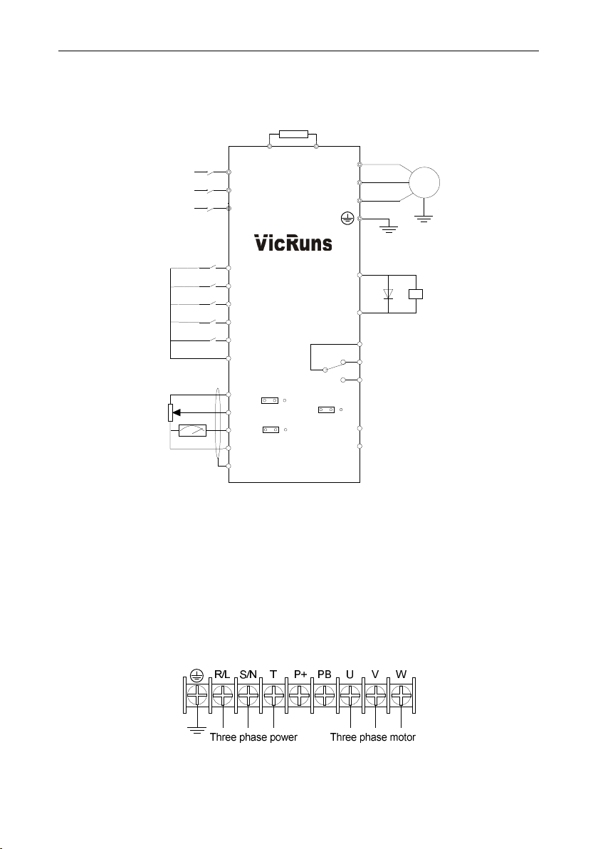
3.1 Standard Wiring Diagram
Brake unit
AI
AO
P+
DO1
+24V
T/A
T/B
T/C
485
R
RS-485+
RS-485-
U
V
W
Relay T output
RS-485
M
DO1 output
Comunication port
Input power
DI terminal
AI terminal
QF
L1/R
L2/S
L3/T
FWD/Stop
REV/Stop
Jog
Coast to stop
Fault reset
VR:1K~10K
R/L
S/N
T
DI1
DI2
DI3
DI4
DI5
GND
10V
AI1
AO1
GND
PB
V A
V A
PE
Fig 3.1-1 Schematic diagram of inverter standard wiring
Precautions are as follows:
1) Terminal ◎refers to Main circuit terminal, terminal ○ refers to control circuit terminal;
2) B which is followed the product model represents standard models built-in brake unit;
3) Braking resistor’s selection is based on the user demand. refer to Table 2-4;
4) Signal lines and power line must be separated alignments, if you want to control cables and power
cable cross, let them cross by 90 degree angle. It is best to choose shielded twisted-pair cabling for
analogue signal, the selection of power cable is shield three-core cable(The specification should
enlarge a class as much as the ordinary electric cables), or follow the inverter user manual.
3.2 Main Circuit Terminals
Three phase 380V: 0.4kW-2.2kW/Three phase, Signal phase 220V: 0.4kW-1.5kW
- 8 -
VD120 Series Inverter User Manual Mechanical and Electrical Installation
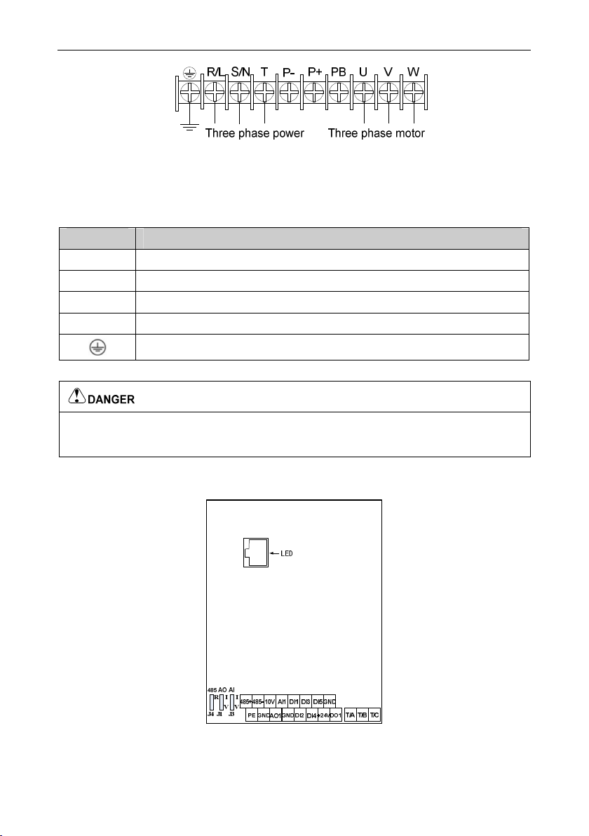
Three phase 380V: 3kW-7.5kW/Three phase 220V: 2.2kW~4.0kW/Signal phase 220V: 2.2kW
Fig 3.2-1 Schematic diagram of main circuit wiring
3.2.1 Function Instruction of Main Circuit Terminals
Table 3-1 Function Instruction of main circuit terminals
Terminals Function Instruction
R/L, S/N, T Power input terminals, external the ac power of grid rated voltage
U, V, W Output terminal of 3phase power supply, external connection of AC 3phase motor
P+, PB External connection of braking resistor terminal
P+, P- Voltage positive and negative terminals on DC side
Grounding terminal
● The voltage class of VD120 series inverter 3phase power has two grades: 220V, 380V, before
connecting power, please make sure the power class on inverter nameplate is the same with the
accessing power. Otherwise do not connect.
3.3 Control Circuit Terminal
3.3.1 Schematic diagram of control board layout
Fig 3.3-1 Schematic diagram of control board layout
- 9 -

Mechanical and Electrical Installation VD120 Series Inverter User Manual
3.3.2 Function Description of Control Circuit Terminal
Table 3-1 Function description of control circuit terminal
Type
Power Supply
Communication 485+-485-
Analog Input AI1-GND
Digital Input
Analog Output AO1-GND
Digital Output DO1
Terminal
Sign
10V-GND
+24V-GND
DI1-GND
DI2-GND
DI3-GND
DI4-GND
DI5-GND
Terminal
10V power
24V power
RS-485
communicati
on terminals
Analog input
terminal 1
Digital input
terminal 1
Digital input
terminal 2
Digital input
terminal 3
Digital input
terminal 4
Digital input
terminal 5
Analog
terminal 1
Digital output
Name
supply
supply
output
1
Function
1. Provide 10V power supply for
external-units.
2. It is generally used as the external
potentiometer power. The potentiometer
resistance range is 1kΩ~10KΩ.
3. Maximum output current 10mA.
4. Provide +24V power supply for external
units, only used as the working power
supply of digital output terminals.
5. The maximum output current 100mA.
6. Don’t use this power as an external
power supply.
Standard RS-485 communication terminal,
should use twisted pair cable
Support 0V~10V voltage or 0/4Ma~20mA
current input, selected by AI jumpers, default
to 0V~10V voltage input.
Multi-function digital input, the function set by
F5-01~F5-05.
Support 0V~10V voltage or 0/4mA~20mA
current output, selected by jumper J3, default
to 0V~10V voltage output
1. Optical coupling isolation, dual polarity
open collector output;
2. Pull-up voltage range: 5V~24V(pull-up
resistance range: 0.48kΩ~10kΩ);
3. Output current range: 2mA~50mA.
- 10 -

VD120 Series Inverter User Manual Mechanical and Electrical Installation
Relay T1
T1/A-T1/B
Relay Output
T1/A-T1/C
Shield Ground PE
Shield cable
normally
closed
terminal
Relay T1
normally
open
terminal
ground
terminal
Contact driving capacity:
AC250V, 3A; DC30V, 5A
1. Used to control cable shield grounding,
when the interference is big on site or
control cable is too long, the PE should
be well grounded to reduce EMC affect.
2. PE terminal is not allowed to connect with
power N line, otherwise will damaged the
inverter.
- 11 -

Operation and Display VD120 Series Inverter User Manual
Chapter 4 Operation and Display
4.1 Introduction to Operation and Display Interface
With the operation panel, it can perform such operations on the inverter as function parameter
modification, inverter working status monitoring and inverter run control (startup and stop).
Refer to Fig 4-1 for the physical appearance and functional zone of the operation panel:
Hz
A
-
MENU
ESC
ENTER
DATA
STOP
RESET
V
+
L/R
FWD/REVRUN
LED DIGITAL PANEL
JOG
REV
RUN
Fig 4.1-1 Operation panel schematic
4.1.1 Keyboard Button Description
Buttons Name Function Description
Programming key
Enter key
Enter or escape from the first level menu and remove the
parameters quickly
Enter the menu step-by-step
Confirm parameters
UP key Increase data or function code progressively
DOWN key Decrease data or function code progressively
Move right to select the displaying parameters circularly in
Right-shift key
stopping and running mode.
Select the parameters modifying digit during the parameter
modification
- 12 -
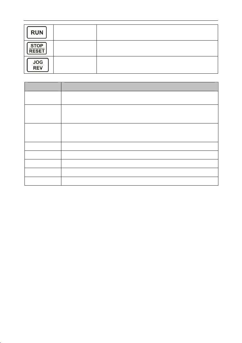
VD120 Series Inverter User Manual Operation and Display
Run key
Stop/Reset key
Quick key The function of this key is confirmed by function code FA-01
4.1.2 Description of Function LED Indictor
Name Description
RUN
FWD/REV
L/R
Hz The unit of frequency(Hz)
A The unit of current(A)
V The unit of voltage(V)
RPM The unit of rotation speed(RPM)
% Unit:%
When it is off, it indicates the inverter is in stop status; when it is on, it indicates
the rotation status; light flashes that inverter in automatic running.
It is the LED indictor for forward/reverse rotation. When it is on, it indicates the
inverter is in forward rotation status; when it is off, it indicates the inverter is in
reverse rotation
When it’s off, it indicates the keypad operation control status; when it’s on, it
indicates the terminal operation control status; when it’s flicker, it indicates the
remote operation control status
This key is used to operate on the inverter in key operation
mode
This key is used to stop in running state and it is limited by
function code F7-01
- 13 -

Function Parameter Table VD120 Series Inverter User Manual
Chapter 5 Function Parameter Table
The symbols in the function table are described as follows:
○——It indicates that the parameter setup value can be modified when the inverter is in run state;
◎——It indicates that the parameter setup value cannot be modified when the inverter is in the run
state;
●——It indicates that the numerical value of the parameter is the actually measured value, which
cannot be modified;
☆——It indicates this parameter is “Factory default parameter” and can be set only by the
manufacturer.
F0 Basic Parameter Group
Function
Code
F0-00
F0-01
F0-02
F0-03
F0-04
Parameter
Name
Motor Control
Mode
Running
Command
Source
Selection
Main Frequency
Source A
Selection
Main Frequency
A Gain
Auxiliary
Frequency
Source B
Selection
Setting Range
0: V/F control
1: SVC
0: Control panel command source
(L/R OFF)
1: Terminal command source
(L/R ON)
2:Communication command
source (L/R flashes)
0: Digital setting (F0-09,
UP/DOWN can be modified, no
memory when power failure)
1: Digital setting (F0-09,
UP/DOWN can be modified,
memory when power failure)
2: AI1
3: Reserved
4: Reserved
5: PULSE setting
6: MS reference
7: Simple PLC
8: PID
9: Communication setting
10: Keypad potentiometer
0.000~10.000 1.000
Same as F0-02 (Main Frequency
Source A Selection)
Default Value
- 14 -
Factory
0
0
10
0
Property
◎
○
◎
○
◎

VD120 Series Inverter User Manual Function Parameter Table
Unit’s digit: frequency source
selection
0: Main frequency source A
1: Main auxiliary operation result
(operational relationship is
determined by ten bits)
2: Main frequency source A switching
Frequency
F0-05
F0-06
F0-07
F0-08
F0-09
F0-10 Max Frequency 50.00Hz~600.00Hz 50.00Hz
F0-11
F0-12
Source
Superposition
Selection
Auxiliary
Frequency
Source B
Range
Reference
Selection when
Superimposed
Auxiliary
Frequency
Source B
Range when
Superimposed
Auxiliary
Frequency
Source B
Offset
Frequency
when
Superimposed
Digital Setting
Frequency
Frequency
Upper Limit
Source
Frequency
Upper Limit
with auxiliary frequency source B
3: Main frequency source A switching
with main and auxiliary operation
result
Ten’s digit: frequency source main
and auxiliary operation relationship
0: Main + auxiliary
1: Main – auxiliary
2: Max value of the two
3: Min value of the two
1: Relative to the max frequency
2: Relative to frequency source A
0%~150% 100%
0.00Hz~max frequency F0-10 0.00Hz
0.00Hz~max frequency (F0-10) 50.00Hz
0: F0-12 setting
1: AI1
2: Reserved
3: Reserved
4: PULSE setting
5: Communication setting
Frequency lower limit F0-14~max
frequency F0-10
0x00
0
0
50.00Hz
○
○
○
○
○
◎
◎
○
- 15 -

Function Parameter Table VD120 Series Inverter User Manual
Frequency
F0-13
F0-14
F0-15
F0-16
F0-17
F0-18
F0-19
F0-20
F0-21
F0-22
Upper Limit
Offset
Frequency
Lower Limit
Frequency
Command
Resolution
Frequency
Command
UP/DOWN
Reference in
Running
Digital Setting
Frequency
Memory
Selection when
Stop
Acceleration
Time 1
Deceleration
Time 1
Acceleration /
Deceleration
Time Unit
Acceleration
and
Deceleration
Time
Reference
Frequency
Command
Source Bound
Frequency
Source
0.00Hz~max frequency F0-10 0.00Hz
0.00Hz~frequency upper limit F0-12 0.00Hz
2: 0.01Hz 2
0: Running frequency
1: Set frequency
0: No memory
1: Memory
0.00s~65000s
0.00s~65000s
0: 1s
1: 0.1s
2: 0.01s
0: Max frequency (F0-10)
1: Setting frequency
2: 100Hz
Unit’s digit: Operation panel
command binding frequency source
selection
0: No binding
1: Digital setting frequency
2: AI1
3: Reserved
4: Reserved
5: PULSE setting
6: MS reference
7: Simple PLC
8: PID
9: Communication setting
Ten’s digit: terminal command
binding frequency source selection
Hundred’s digit: communication
0
0
Model
dependent
Model
dependent
1
0
0x0000
○
○
●
◎
○
○
○
◎
◎
○
- 16 -

VD120 Series Inverter User Manual Function Parameter Table
command binding frequency source
selection
Thousand’s digit: Automatic
operation command binding
frequency source selection
F0-23
F1 Start/Stop Control Group
Communicatio
n Protocol
Selection
0: Modbus 0
●
Function
Code
F1-00 Start Mode
F1-01
F1-02
F1-03
F1-04
F1-05
F1-06
F1-07
F1-08 Stop Mode
F1-09
Parameter
Name
Starting
Frequency
Startup
Frequency
Holding Time
Starting DC
Braking
Current/
Pre-excitation
Current
Starting DC
Braking Time /
Pre-excitation
Time
Speed
Tracking Mode
Speed
Tracking
Speed
Speed
Tracking
Current
Initial
Frequency of
Stop DC
Braking
Setting Range
0: Direct start
1: Speed tracking restart
2: Pre excitation start (AC
asynchronous )
0.00Hz~10.00Hz 0.50Hz
0.00s~100.0s 0.0s
0%~100% 0%
0.0s~100.0s 0.0s
0: Starting from the stop frequency
1: Starting from zero speed
2: Starting from the maximum
frequency
1~100 20
100%~150% 125%
0: Decelerate to stop
1: Coast to stop
0.00Hz~max frequency 0.00Hz
Default Value
Factory
0
0
0
Property
○
○
◎
◎
◎
◎
○
◎
○
○
- 17 -

Function Parameter Table VD120 Series Inverter User Manual
Waiting Time of
F1-10
F1-11
F1-12
F1-13
F1-14
F1-15
F1-16
F1-17
F1-18
F1-19 Run Direction
Stop DC
Braking
Stop DC
Braking
Current
Stop DC
Braking Time
Stop
Frequency
Stop
Frequency
Holding Time
Restart
Selection Upon
Power Failure
Waiting Time of
Restart Upon
Power Failure
Operation
Mode of Set
Frequency is
Lower than the
Frequency
Lower Limit
Start Selection
of Set
Frequency is
Lower than the
Start
Frequency
0.0s~100.0s 0.0s
0%~100% 0%
0.0s~100.0s 0.0s
0.00Hz~max frequency 0.50Hz
0.0s~60.0s 0.0s
0: Enabled
1: Disabled
0.0s~60.0s 0.0s
0: Running with frequency lower limit
1: Stop
2: Zero speed running
0: Don’t start
1: Zero speed running
0: Same direction
1: Opposite direction
0
0
1
0
○
○
○
○
○
○
○
○
◎
○
F1-20
F1-21
F1-22
F1-23
Reverse
Control Enable
FWD/REV
Rotation
Dead-zone
Time
Dynamic
Braking Enable
Braking Usage
Rate
0: Allow reverse
1: Prohibit reverse
0.0s~3000.0s 0.0s
0: Disabled
1: Enabled
0%~100% 100%
- 18 -
0
0
○
○
○
○

VD120 Series Inverter User Manual Function Parameter Table
0: The whole is valid
Over-excitation
F1-24
F1-25
F1-26
F1-27
F1-28
F1-29
F2 Motor Parameter
Function
Code
F2-00
Effective
Range
Over-excitation
Gain
Over-excitation
Filter
Coefficients
Acceleration/D
eceleration
Mode
Time Ratio of S
Curve Start
Segment
Time Ratio of S
Curve End
Segment
Parameter
Name
Motor Type
Selection
1: Only overpressure stall enable
effectively
2: Only deceleration process
effectively
3: The whole is invalid
0~200 100
0~10 3
0: Straight-line
acceleration/deceleration
1: S curve acceleration/deceleration
A
2: S curve acceleration/deceleration
B
0.0%~(100.0%-F1-29) 30.0%
0.0%~(100.0%-F1-28) 30.0%
Setting Range
0: Ordinary asynchronous motor
1: Frequency conversion
asynchronous motor
1
0
Factory
Default Value
0
◎
○
○
◎
◎
◎
Property
◎
F2-01
F2-02
F2-03
F2-04
F2-05
F2-06
Rated Motor
Power
Rated Motor
Voltage
Rated Motor
Current
Rated Motor
Frequency
Rated Motor
Rotation Speed
Asynchronous
Motor Stator
Resistance
0.1kW~11.0kW
1V~1000V
0.01A~100.00A
0.01Hz~max frequency
1RPM~65535RPM
0.001Ω~65.535Ω
- 19 -
Model
dependent
Model
dependent
Model
dependent
Model
dependent
Model
dependent
Tune
parameter
◎
◎
◎
◎
◎
◎

Function Parameter Table VD120 Series Inverter User Manual
Asynchronous
F2-07
F2-08
F2-09
F2-10
F2-26 Tune Selection
F3 Motor Vector Control Parameter
Function
Code
F3-00
F3-01
F3-02
F3-03
F3-04
F3-05
F3-06
F3-07
Motor Rotor
Resistance
Asynchronous
Motor Leakage
Inductive
Reactance
Asynchronous
Motor Mutual
Inductive
Reactance
Asynchronous
Motor No-load
Current
Parameter
Name
Speed Loop
Proportional
Gain 1
Speed Loop
Integral Time 1
Switch
Frequency 1
Speed Loop
Proportional
Gain 2
Speed Loop
Integral Time 2
Switch
Frequency 2
Vector Control
Slip Gain
Speed Loop
Filter Time
Constant
0.001Ω~65.535Ω
0.01mH ~655.35mH
0.1mH~6553.5mH
0.01A~F2-03
0: No operation
1: Asynchronous motor static tuning
2: Asynchronous motor complete
tuning
Setting Range
01~100 30
0.01s~10.00s 0.50s
0.00Hz~F3-05 5.00Hz
1~100 20
0.01s~10.00s 1.00s
F3-02~max frequency 10.00Hz
20%~200% 100%
0.000s~0.100s 0.000s
Tune
parameter
Tune
parameter
Tune
parameter
Tune
parameter
0
Factory
Default Value
◎
◎
◎
◎
◎
Property
○
○
○
○
○
○
○
○
- 20 -

VD120 Series Inverter User Manual Function Parameter Table
0: Encode F3-10 setting
1: AI1
2: AI2
3: AI3
4: PULSE setting
5: Communication setting
6: MIN (AI1, AI2)
7: MAX (AI1, AI2)
The full scale of options 1~7
corresponding to the F3-10
0%~200.0% 150.0%
0: Encode F3-12setting
1: AI1
2: AI2
3: AI3
4: PULSE setting
5: Communication setting
6: MIN (AI1, AI2)
7: MAX (AI1, AI2)
The full scale of options 1~7
corresponding to the F3-12
0%~200.0% 150.0%
0~60000 2000
0 ~60000 1300
0~60000 2000
0~60000 1300
0: Disabled
1: Enabled
0
0
0
○
○
○
○
○
○
○
○
○
F3-09
F3-10
F3-11
F3-12
F3-13
F3-14
F3-15
F3-16
F3-17
Motor Torque
Upper Limit
Source
Digital Setting
for Motor
Torque Upper
Limit
Brake Torque
Upper Limit
Source
Digital Setting
for Brake
Torque Upper
Limit
Excitation
Adjustment
Proportional
Gain
Excitation
Adjustment
Integral Gain
Torque
Adjustment
Proportional
Gain
Torque
Adjustment
Integral Gain
Speed Loop
Integral
Separation
Enable
- 21 -

Function Parameter Table VD120 Series Inverter User Manual
Max Weak
F3-20
F3-21
F3-22
F3-23
F3-24
F3-25
F3-26
F3-27
F4 Motor V/F Control Parameter
Magnetic
Current
Weak Magnetic
Automatic Gain
Adjustment
Weak Magnetic
Integral
Multiples
Torque Boost
Coefficient
Torque Boost
Cutoff
Frequency
Exciting
Current
Compensation
Gain
Torque Current
Compensation
Gain
Torque
Response Gain
1%~300% 50%
10%~500% 100%
2~10 2
0.0%~60.0% 10.0%
0.00Hz~max frequency 20.00Hz
0~500 0
0~500 0
1~1000 10
◎
○
○
○
◎
○
○
○
Function
Code
F4-00
F4-01
F4-02
F4-03
Parameter
Name
V/F Curve
Setting
Torque Boost
Mode Selection
Manual Torque
Boost
Manual Torque
Boost Cutoff
Frequency
Setting Range
0: Straight line V/F
1: Multipoint V/F
2: Square V/F
3: 1.2#power V/F
4: 1.4#power V/F
5: 1.6#power V/F
6: 1.8#power V/F
7: V/F complete separation mode
8: V/F half separation mode
0: Automatic torque boost
1: Manual torque boost
0.0%~30.0%
0.00Hz~max frequency 50.00Hz
Default Value
dependent
- 22 -
Factory
0
0
Model
Property
◎
◎
○
◎

VD120 Series Inverter User Manual Function Parameter Table
MS V/F
F4-04
F4-05
F4-06
F4-07
Frequency
Point 1
MS V/F
Voltage Point 1
MS VF
Frequency
Point 2
MS V/F
Voltage Point 2
0.00Hz~F4-06 0.00Hz
0.0%~100.0% 0.0%
F4-04~F4-08 0.00Hz
0.0%~100.0% 0.0%
◎
◎
◎
◎
F4-08
F4-09
F4-10
F4-12
F4-14
F4-15
F4-16
F4-17
MS V/F
Frequency
Point 3
MS V/F
Voltage Point 3
V/F Slip
Compensation
Gain
V/F Oscillation
Suppression
Gain
The Separation
of V/F Voltage
Source
V/F Separation
Voltage Digital
Setting
V/F Separation
Voltage Rise
Time
V/F Separation
Voltage Fall
Time
F4-06~Rated motor frequency
(F2-04)
0.0%~100.0% 0.0%
0.0%~200.0% 20.0%
0~100
0: Digital setting (F4-15)
1: AI1
2: Reserved
3: Reserved
4: PULSE setting
5: MS instruction
6: Simple PLC
7: PID
8: Communication given
Remark: 100% corresponding rated
motor voltage
0V~rated motor voltage 0V
0.0s~1000.0s
Remark: Indication the time that 0V
rise to rated motor voltage
0.0s~1000.0s
Remark: Indication the time that
rated motor voltage drop to 0V
0.00Hz
Model
dependent
0
5.0s
5.0s
◎
◎
◎
○
○
○
○
○
- 23 -

Function Parameter Table VD120 Series Inverter User Manual
F5 Input Terminal
Function
Code
F5-00
F5-01
F5-02
F5-03
F5-04
F5-05
Parameter
Name
Terminal
Command
Mode
DI1 Terminal
Function
Selection
DI2 Terminal
Function
Selection
DI3 Terminal
Function
Selection
DI4 Terminal
Function
Selection
DI5 Terminal
Function /
HDI1 Pulse
Input Function
Selection
(Optional)
Setting Range
0: Two-line mode 1
1: Two-line mode 2
2: Three-line mode 1
3: Three-line mode 2
4: Alternate control
5: Back and forth control
0: No function
1: Forward running (FWD)
2: Reverse running (REV)
3: Three-line mode run control
4: Forward Jog (FJOG)
5: Reverse Jog (RJOG)
6: Coast to stop
7: Run pause
8: Fault reset (RESET)
9: External fault normally open input
10: External fault normally closed
input
11: Terminal UP
12: Terminal DOWN
13: UP/DOWN setting clear (terminal,
keyboard)
14: Switching frequency source
15: Frequency source A switching
with preset frequency
16: Frequency source B switching
with preset frequency
17: MS reference terminal 1
18: MS reference terminal 2
19: MS reference terminal 3
20: MS reference terminal 4
21: Acceleration and deceleration
time selection terminal 1
22: Acceleration and deceleration
time selection terminal 2
23: PULSE frequency input
(Only effective for HDI1)
24: Control command switch terminal
1
25: Control command switch terminal
2
Factory
Default Value
0
1
2
4
6
8
Property
◎
◎
◎
◎
◎
◎
- 24 -

VD120 Series Inverter User Manual Function Parameter Table
26: Immediate DC braking
27: Deceleration DC braking
28: External stop terminal 1 (Only
effective for keypad control)
29: External stop terminal 2
(According to the deceleration time 4)
30: Emergency stop
31: PID pause
32: PID integral pause
33: Reverse PID action direction
34: PID parameter switching
35: PLC pause
36: PLC state reset
37: Swing frequency pause
38: Swing frequency reset
39: Switching between speed control
and torque control
40: Torque control prohibit
41: Acceleration and deceleration
prohibit
42: Reverse prohibit
43: Frequency modification prohibit
44: Counter input
45 Counter reset
46: Length count input
47: Length reset
48: Motor selection terminal
49: Reserved
50: User defined failure 1
51: User defined failure 2
52: Cleared the running time
53: Switching between two-line and
three-line mode (Switch is invalid in
running)
54~59: Reserved
Unit’s digit: DI1
0: High level effective
1: Low level effective
F5-10
F5-12 DI Filter Time 0.000s~1.000s 0.010s
DI1 Terminal
Mode Selection
1 Effectively
Ten’s digit: DI2, same as above
Hundred’s digit: DI3, same as above
Thousand’s digit: DI4, same as
above
Ten thousand’s digit: DI5, same as
above
0x00000
◎
○
- 25 -

Function Parameter Table VD120 Series Inverter User Manual
F5-13
F5-14
F5-15
F5-16
F5-17
F5-18
F5-19
F5-20
F5-21
F5-22
F5-23
F5-24
F5-25
F5-26 AI 1 Filter Time 0.00s~10.00s 0.10s
DI1 Close
Delay Time
DI2 Close
Delay Time
DI3 Close
Delay Time
DI1 Open
Delay Time
DI2 Open
Delay Time
DI3 Open
Delay Time
Terminal
UP/DOWN
change rate
AI Curve
Selection
AI is Lower
than Min Input
Setting
Selection
AI Curve 1 Min
Input
Corresponding
Setting of AI
Curve 1 Min
Input
AI Curve 1 Max
Input
Corresponding
Setting of AI
Curve 1 Max
Input
0.0s~3600.0s 0.0s
0.0s~3600.0s 0.0s
0.0s~3600.0s 0.0s
0.0s~3600.0s 0.0s
0.0s~3600.0s 0.0s
0.0s~3600.0s 0.0s
0.001Hz/s~65.535Hz/s 1.000Hz/s
AI1 curve selection
1: Curve 1
(2 point, see F5-22~F5-26)
2: Curve 2
(2 point, see F5-27~F5-31)
3: Curve 3
(2 point, see F5-32~F5-36)
4: Curve 4
(4 point, see b2~00-b2-07)
5: Curve 5
(4 point, see b2-08~b2-15)
AI1 is lower than min input setting
selection
0: Corresponding to the min input
setting
1: 0.0%
-10V~F5-24 0.00V
-100.0%~+100.0% 0.0%
F5-22~+10.00V 10.00V
-100.0%~+100.0% 100.0%
1
0
◎
◎
◎
◎
◎
◎
○
○
○
○
○
○
○
○
- 26 -
 Loading...