

Page 1
USER GUIDE | UG:111
VI Brick® AC Front End
Evaluation Board
November 2012
Contents Page
Features 1
Introduction 1
Set Up 3
Bill of Materials 5
Recommended 6
Hardware
Thermals 6
Ordering Info 6
Features
n Oscilloscope probe jack for output voltage and ripple measurements
n Simple to use
n Ring lug, screw terminal, and solder connection options
n Replaceable fuse (5 A, 216 Littelfuse recommended)
IMPORTANT NOTICE:
Please read this user guide before operating evaluation board.
Introduction
The VI Brick® AC Front End Evaluation Board oers a convenient means to evaluate
the performance of Vicor’s VI Brick AC Front End module and has been optimized for
user convenience. Refer to the table below for operating conditions and limits.
This product contains an input line filter. It is important to remember the response
of the AC line filter is dependent upon the wiring connected to the evaluation board.
Care should be exercised to minimize stray source impedances in order to fully
exercise the features of the converter.
UG:111 vicorpower.com Applications Engineering: 800 927.9474 Page 1
Page 2

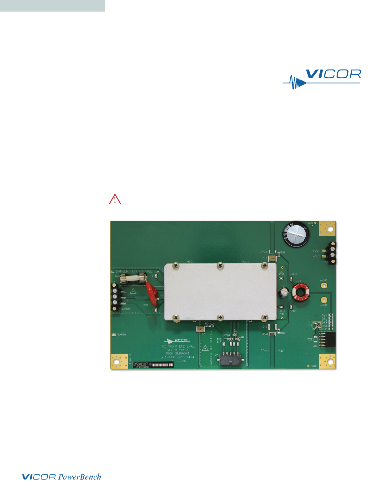
Figure 1
VI Brick® AC Front End
Evaluation Board layout and
dimensional drawing,
component side.
Evaluation Board Basic Specifications and Operating Limits
Please use the following table for operating limits:
Table 1
Operating Limits
Description Specification Notes
Input Range 85 – 264 Vac Universal input
Output voltage 48 Vdc Partially Regulated, SELV
Output Power 330 W Over entire input range
Operating temperature -40 to 85°C
and Z01
Output capacitance 6,000 to 12,000μF 63V rating
Note: VI Brick AC Front End Module operating temperature will depend on its Product Grade as
specified in the datasheet.
Limited by hold-up capacitor
Please refer to Figure 1 for locations of the input and output connections as viewed
from the component side. Wires may be soldered directly to the pads instead of ring
lugs if desired to minimize circuit impedances.
UG:111 vicorpower.com Applications Engineering: 800 927.9474 Page 2
Page 3

DANGER! HIGH VOLTAGE! DANGER! HOT SURFACE!
The VI Brick® AC Front End Evaluation Board contains exposed hazardous voltages.
These voltages are within the area marked by the hashed line on the board.
The VI Brick AC Front End Evaluation Board may be operated at surface temperatures
which may pose a thermal hazard to the operator. Because of the thermal and voltage
hazards, be careful not to touch any exposed surface unless the power is disconnected
and the evaluation board has been given sucient time to cool. The evaluation board
is not intended for use in end item equipment.
Set Up
The Customer Evaluation Board should be set up as follows:
Note: Care should be taken to avoid reversing polarities if connecting to the opposite (solder) side of
the board.
AC Input Connections (J01) DANGER! HIGH VOLTAGE!
J01, the screw terminal connector, is for connection of AC input to the AC-DC
converter evaluation board. The interconnect leads should be appropriate for the
current and voltage supplied to the board.
For single phase power, connect LINE to the pin marked L, NEUTRAL to the pin
marked N and earth ground to the pin marked EARTH. Corresponding wires in an IEC
cable are brown, blue, and yellow with a green stripe.
The board can be used with three phase power. Connect LINE1 to L and LINE2 to N.
Earth ground should still be connected to the EARTH terminal of J1.
Table 2
Output Connector Ratings
+OUT, –OUT
There are several connections available on the VI Brick AC Front End Evaluation
Board. Table 1 lists the available connectors and their current rating. Do not exceed
the rating of the connector or the module.
Connector
J02 10 A Hold-up capacitor
J03
boards
Ring Lugs 100 A General Purpose
Rating
12 A (3 A/contact)
Mating PRM and BCM eval
Recommended
Connection
Output bulk (electrolytic) capacitance must be attached across the output of the VI
Brick AC Front End Evaluation Board. It is recommended that the hold-up capacitor is
to be applied between H12 and H10 or H14 and H10. RTV adhesive should be used if
laying the capacitor on its side. Refer to table 1 from previous page for the
appropriate range of output capacitance.
UG:111 vicorpower.com Applications Engineering: 800 927.9474 Page 3
Page 4

The load should be connected to +OUT and –OUT terminals of the evaluation board
with short leads of suitable gauge to carry the output current and minimize losses.
A sucient number of terminal connections should be used to ensure that no
terminal sees more than its maximum rated current. The evaluation board can be
connected directly to the application for which the module is intended. However
the interconnect impedances between the evaluation board and the application
can greatly aect the transient response. For applications where transient response
is critical, the user should consider mounting the VI Brick® AC Front End module
directly to the target application PCB. Test points TP12 (–OUT) and TP07 (+OUT) can
be used to monitor the output and are located on the PCB adjacent to the output
terminals of the AC Front End module.
Earth Connections
There are several earth connections available on the board. Earth must be connected
via a low impedance connection in order for the internal line filter to function. These
earth connections also provide a safety ground for the baseplate of the module.
Earth may optionally be connected to either of the VI Brick AC Front End outputs in
order to provide a positive or negative voltage rail with respect to earth.
Output Voltage Measurement Jack (J12)
This connector is provided to make accurate measurements of the output ripple
voltage of the VI Brick AC Front End. Many types of scope probes may be directly
connected to this point if the probe is equipped with a removable plastic sheath.
To avoid creating ground loops when making measurements of the output or input
voltage, these measurements should be made separately.
Figure 2
VI BRICK AC Front End
Output capacitor (C29) can be
added to reduce switching frequency
voltage ripple at the probe.
(Click on drawing to view larger.)
UG:111 vicorpower.com Applications Engineering: 800 927.9474 Page 4
Page 5

Table 3
Bill of Materials
Ref. Description Digi-Key Digi-Key Future Future
Desc. Manufacturer Part # Manufacturer Part #
CAP X7R 2200pF
C01
10% 250V 2220
CAPY X7R 4700pF
C12
10% 250V 2220
C13
C29
C30
C31
C32
C33
C34
C35
C36
C37
C38
C39
F01
SMD, 5x20
H03 & CAP ALEL 6800uF
H07 20% 63V 25X50
J01
BLK SMD
J02
BLK SMD
CONN 10POS
J03 90DEG THRUHOLE
FEMALE 0.1SPC
CONN 5POS
J05 SINGLE ROW Molex WM1893-ND TE Connectivity 1445057-5
RIGHT ANGLE
JP02
5% 2010
JP03 NOT APPLIED NOT APPLIED NOT APPLIED NOT APPLIED NOT APPLIED
L01
10% 5mA 0805 150K-ND
L05
600uH 30% 10A
PS01 Model Specific Vicor Model Specific Vicor Model Specific
R01
1/8W 1% 0805
R09
1/4W 1% 1206
R10 NOT APPLIED NOT APPLIED NOT APPLIED NOT APPLIED NOT APPLIED
VAR MOV, 300V
Z01 10KA 20mm Littelfuse
DIA RADIAL
NOT APPLIED NOT APPLIED NOT APPLIED NOT APPLIED NOT APPLIED
CAP X7R .1uF
10% 25V 0805
CAP ALUM 100UF
63V 20% RADIAL
FUSE HOLDER,
CON 3CKT TERM
CON 2 CKT TERM
RES 0 OHM 3/4W
IND 15.0uH Bourns Inc. CV201210- No Stock No Stock
IND COM MODE
RES 6.81 OHM
RES 2.2 OHM
Murata 490-3480-2-ND Murata GA355QR7GF222KW01L
Murata 490-3482-2-ND Murata GA355DR7GF472KW01L
Murata 490-1673-2-ND Murata GRM21BR71E104KA01L
Nichicon UVY1J101MPD-ND Nichicon UVY1J101MPD
Wickmann F4546-ND Schurter 31.8225
Kemet 493-1135-ND Nichicon UVZ1J682MRD
No Stock No Stock Weco 140-A-126-SMD/03
No Stock No Stock Weco 140-A-126-SMD/02
Sullins
Electronics
Vishay Dale 541-0.0WTR-ND Vishay Dale CRCW20100000Z0EF
Vishay Dale 541-6.81CCTRND Vishay Dale CRCW08056R81FKEA
Vishay Dale 541-2.20FFTRND Vishay Dale CRCW12062R20FKEA
S5519-ND
Stocked by Vicor, part#: 37052-601
TMOV20RP30
0EL2T7-ND
Sullins
Electronics
Littelfuse TMOV20RP300E
PPTC052LJBN-RC
UG:111 vicorpower.com Applications Engineering: 800 927.9474 Page 5
Page 6

Input Current Measurement
A current probe can be passed around either input lead connected to the VI Brick® AC
Front End Evaluation Board. Note that an input capacitor on the evaluation board is
downstream of this measurement point.
Enable (EN) DANGER! HIGH VOLTAGE!
The EN pin can be used to disable the VI Brick AC Front End module. Connecting EN
to the IN-PFM pin will disable the module. This will also clear any latching output OVP
fault if one has occurred. Note that the EN pin is referenced to the primary (hazardous
voltage) side of the converter. Warning: The EN Pin, or the –IN PFM Pin must not be
connected to line or output of the VI Brick AC Front End.
Efficiency Measurement
As the VI Brick AC Front End module can deliver and consume large currents, the eect
of the PCB must be considered when making an eciency measurement. Be certain to
accurately measure the voltage using test points TP08 (LINE1) , TP14 (LINE2/NEUTRAL),
TP18 (–OUT), and TP01 (+OUT). Using these test points will more closely represent the
eciency of the VI Brick AC Front End module.
Hardware
The hardware kit provided with the evaluation board includes the following:
n (3) #10-32 screws n (6) #10-32 lock washer
(for +OUT, -OUT, and Earth terminals) (for +OUT, -OUT, and Earth terminals)
n (3) #10-32 hex nut n (1) 6800 uF hold-up capacitor
(for +OUT, -OUT, and Earth terminals) (can be applied between H03 and
H07, H12 and H10, or H14 and H10)
Ring lugs are also recommended for making output connections.
Thermals
For most lab environments a fan blowing across the evaluation board is recommended.
See VI Brick Thermal Management Application Note at:
www.vicorpower.com/documents/application_notes/AN200_VIBrickTherm.pdf
or contact Vicor Applications Engineering for assistance (800) 927-9474.
Ordering Information
The evaluation board is specified by replacing the “–00” sux with “–CB” on the
VI Brick AC Front End model number.
The Power Behind Performance
Rev 1.4 12/2013 vicorpower.com Applications Engineering: 800 927.9474 Page 6
 Loading...