

Page 1
USER GUIDE | UG:301
PI31xx-xx-EVAL1 Cool-Power® ZVS Isolated
DC-DC Converter Evaluation Board
Chris Swartz
Principal Applications Engineer
May 2013
Contents Page
Introduction 1
Product Description 2
Board Connections 2
Thermal Considerations 3
Max I/O Ratings 5
Schematic
BOMs 6
Test Setup 11
PCB Artwork 12
Mechanical Outline 14
Ordering Information 14
Introduction
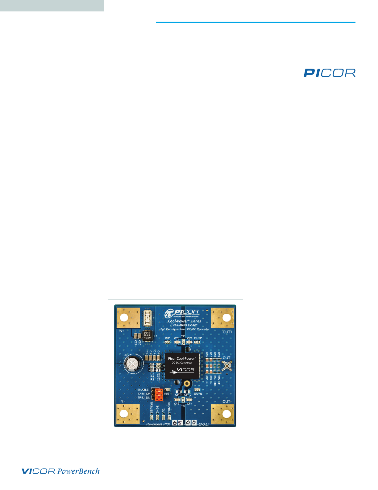
The PI31xx-xx-EVAL1 evaluation board allows the user to test the basic operating
principles of the PI31xx series of high density DC-DC power converters and experience
the performance and value of this solution compared to alternate conventional
solutions. Each evaluation board is populated with the components that could be used
in a final design. It is not designed or intended to be used in end product applications.
Please read this document prior to the connection of test equipment and refer to the
product datasheet for device specifications, descriptions and characteristics. Remember
to follow good lab safety practices and use safety glasses at all times.
The PI31xx-xx-EVAL1 is configured to support one single input and one single output.
Each board oers pin strap options for trimming the output voltage up and down,
turning the converter on and o and adding EMI system “Y” capacitors. Additional
parts are included to compensate for line impedance associated with long leads from
the bench power supply to the converter. Additional component footprints are made
available to allow the user to test dierent design configurations that may be required
to meet their end needs. Kelvin type test points are included to allow for easy and
convenient connections of testing instruments for evaluation of eciency, line/load
regulation and transient response. A low impedance oscilloscope connection using a
Johnson jack is included for ripple measurement and evaluation of the output voltage
during transient events. Each demo board is equipped with a heatsink to allow high
power operation with a small amount of air flow and to allow operation of the board
over various temperature extremes.
Figure 1.
PI31xx-xx-EVAL1
Evaluation Board
UG:301 vicorpower.com Applications Engineering: 800 927.9474 Page 1
Page 2

Cool-Power® PI31xx Series Product Description
The PI31xx operates over a wide range input, delivering 50 W or 60 W output power
depending on the individual model number. The PI31xx Series is available in a space
saving surface mountable 0.87” x 0.65” x 0.265” Power –System –in – a – Package (PSiP),
achieving ~50% space reduction versus alternative solutions.
The switching frequency of 900kHz allows for small input and output filter components
which further reduces the total size and cost of the overall system solution. The output
voltage is sensed and fed back to the internal controller using a proprietary isolated
magnetic feedback scheme which allows for high bandwidth and good common mode
noise immunity.
The PI31xx Series requires no external feedback compensation and oers a total
solution with a minimum number of external components. A rich feature set is
oered, including + 10%, -20% output voltage trim capability (depending on the model
number), remote enable, over-voltage protection, adjustable so-start, over-current
protection with auto-restart to protect against both short circuit and overload and over
and under input voltage lockout. A unique temperature monitor and protection circuit
is included that provides an analog voltage proportional to the internal die temperature,
as well as over temperature shutdown, restart and over temperature fault alarm signal.
Board Connections
1. Connect Test Equipment
a. Connect the input DC power supply to the target board as shown in Figure 6.
The negative terminal should be wired to –IN and the positive terminal should
connect to the positive terminal of the DMM wired as a DC Ammeter. Be sure
that the proper sized wires are used to allow minimum voltage drop for a
maximum input current of up to 4 A. Use ring lugs mated to the included
fasteners on the evaluation board. If your input power supply has remote sense
capability, it can be wired to the INN and INP test points if desired. Connect the
positive terminal of the DMM to the +IN lug on the evaluation board.
b. Connect the primary side DMM (for measuring the input voltage) to INN and
INP respectively.
c. Connect the oscilloscope as shown in Figure 6 if you are planning to measure
both primary and secondary signals at the same time. If you do not have an
isolated dierential amplifier, it is important to note that simultaneous
measurement of both primary and secondary referenced signals using an
oscilloscope with a grounded chassis is not recommended, as it will short circuit
the primary to secondary isolation barrier. Floating the oscilloscope is also not
recommended due to the large capacitance introduced by this long standing
practice. The best practice is to use an isolated dierential amplifier or use an
oscilloscope with isolated channels. That is, the input returns are isolated from
each other and earth ground.
d. Connect the output DC DMM to the test points OUTN and OUTP. These test
points are done in a Kelvin type manner so that they have no high current
flowing in them.
e. Connect the DC Load to the output lugs OUT+ and OUT-. It is critical for this
connection to be low inductance.
UG:301 vicorpower.com Applications Engineering: 800 927.9474 Page 2
Page 3
2. Default Pin Strap Configuration
a. Ensure the pin straps are in the following default locations before proceeding:
nENABLE = Not Used (enabled)
nTRIM_UP = Not Used
nTRIM_DN = Not Used
nOPT1 = Not Used
nOPT2 = Not Used
3. Pin Strap Functions
a. ENABLE – adding a strap on this pin will cause the converter to shut down.
b. TRIM_UP – Adding a strap in this location will adjust the output voltage
up by 10%.
c. TRIM_DN – Adding a strap in this location will adjust the output voltage down
by 10%. Only one strap can be connected at a time. If both trim straps are out,
the output voltage should be set to the model’s nominal output.
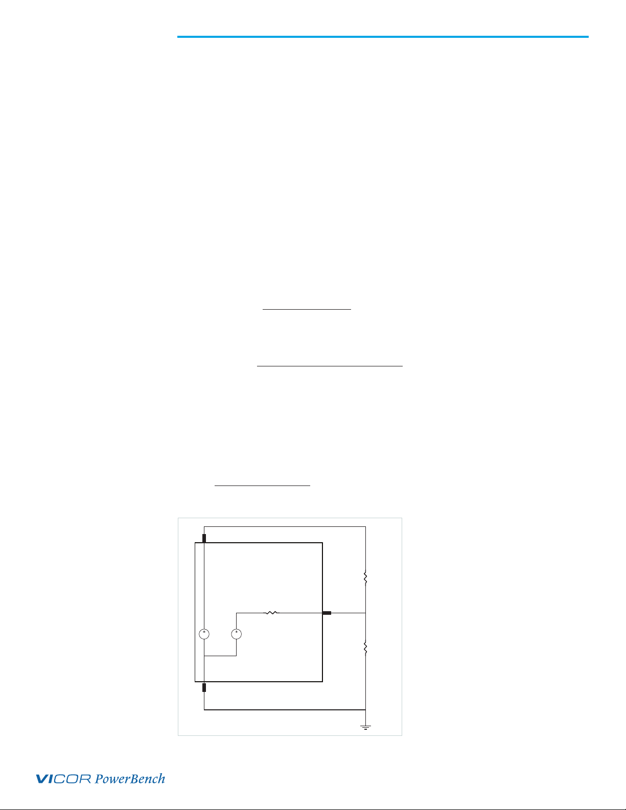
4. Trimming And Soft Start
a. For those customers who wish to trim to another voltage by changing the preset
trim resistors to another value, the trim equation shown in Figure 2 can be used:
Figure 2.
PI31xx Trim Equation
Figure 3.
PI31xx Soft Start Equation
Figure 4.
PI31xx Trimming Equivalent
Circuit
R
INT
+ V
)
nom
nom
V
(
–Vout
[
ref
desired
•
V
)
−6
+ V • V
ERO
) +
nom
V
desired
desired
ref
]
REF
R
= (–V
low
R
high
Where: R1 = Rlow R3 = Rhigh VERO = 4.9 and Vref can be found in the appropriate
model datasheet.
Figure 3 shows an equation for so start configuration where C7 = C
C
REF
desired
= (–RSS) •
T
ssdesired
=
ENABLE
•
)
– 230 • 10
23000
–Vout
(
–Vout
(
PI31xx
Rhigh
VERO
10k
RSS
Vref
TRIM/SS
•
Rlow
•
SGND
•
UG:301 vicorpower.com Applications Engineering: 800 927.9474 Page 3
Page 4

Table 1.
PI31xx-xx-EVAL1
Input-Output Pin Description
Thermal Considerations
The PI31xx-xx-EVAL1 is supplied with optional heat sinks. At present, Picor oers four
dierent heat sink options to accommodate the customers space and cooling needs.
Heatsinks are available in two sizes, one with 6.3mm fins and the other with 11mm fins.
Each of those heatsinks can be ordered with a specific air flow direction in mind, both
cross flow and longitudinal are supported. Please refer to the product website
www.vicorpower.com for more information.
Pin
Name
IN+ Input/Lug Primary side positive input voltage terminal.
IN- Input/Lug Primary side negative input voltage terminal.
OUT+ Output/Lug Isolated secondary DC output voltage positive terminal.
OUT- Output/Lug Isolated secondary DC output voltage negative terminal.
TM Test/Pin Temperature measurement output pin with respect to SGND. 3V=300°K 10mV/°K
SGND Test/Pin Signal ground, primary side referenced.
TRIM/SS Test/Pin
respect to SGND.
ENABLE Test/Pin Allows for monitoring of the ENABLE signal with respect to SGND.
INN Test/Pin
test point.
INP Test/Pin
test point.
YN Output/Pad
system ground.
YP Output/Pad
system ground.
OUTP Test/Pin
test point.
OUTN Test/Pin
test point.
OUT Test/PIn PCB test jack for low noise measurement of the output voltage.
Type Description
Monitor pin for the soft start voltage and trim voltage reference with
Kelvin sense connection for input supply (-) and input voltage measurement
Kelvin sense connection for input supply (+) and input voltage measurement
Optional test pad for connection of optional “YN” capacitor to external
Optional test pad for connection of optional “YP” capacitor to external
Kelvin sense connection for output voltage (+) and output voltage measurement
Kelvin sense connection for output voltage (-) and output voltage measurement
Table 2.
PI31xx-xx-EVAL1
Evaluation Board
Pin Strap and Jumper
Description
Name Description
ENABLE If strap is installed, unit is turned off. If strap is removed, unit will be enabled.
TRIM_UP If strap is installed, PI3105 trims output voltage up 10%
TRIM_DN If strap is installed, PI3105 trims output voltage down 10%
OPT1 Allows optional connection of heat sink assembly to secondary return (-IN)
OPT2 Allows optional connection of heat sink assembly to secondary return (-OUT)
UG:301 vicorpower.com Applications Engineering: 800 927.9474 Page 4
Page 5

Table 3.
PI31xx-xx-EVAL1
Evaluation Board
Maximum I/O Ratings
Name Max Voltage Max Current
IN+ 100 V 20 A
IN- 100 V 20 A
OUT+ 20 V 20 A
OUT- 20 V 20 A
TRIM_DN 10 V 100 mA
OPT1 10 V 100 mA
OPT2 10 V 100 mA
OUT 10 V 100 mA
INP 10 V 100 mA
INN 10 V 100 mA
ENABLE 10 V 100 mA
TRIM/SS 10 V 100 mA
SGND 10 V 100 mA
TM 10 V 100 mA
OUTP 20 V 100 mA
OUTN 20 V 100 mA
UG:301 vicorpower.com Applications Engineering: 800 927.9474 Page 5
Page 6

Figure 5.
Schematic Diagram
OUTP
–OUT
OUT–
OUTN
OPT2
YN
OUT+
OUT
Scope
C17 C18 C19
C16
C13 C14 C15
C9 C10 C11 C12
C8
YP
CY2
+OUT
YP
HS
YN
PI31xx
CY1
4.7nF 4.7nF
TM
TRIM/SS
ENABLE
R2
100 K
C6 C7
390 pF DNP
C5
+
C3
C2
C20C21
R3
301 K
TRIM_UP
C4
R4
100
ENA
R1
TRIM_DN
C1
SGND
90.9 K
+IN
TM
INPSGND
L1
CY3 CY4
4.7nF 4.7nF
HS
–IN
OPT1
INN
ENABLE TRIM/SS
F1
IN+
IN–
UG:301 vicorpower.com Applications Engineering: 800 927.9474 Page 6
Page 7

Table 4.
PI3101-00-EVAL1
Evaluation Board BOM
Item
Qty Ref Design Part # Value U/M Description
1. 1 U1 PI3101-00-HVIZ NA EA Picor PI3101-00 High Density PSiP
2. 12 C8-C19
3. 6
4. 4 CY1-CY4
5. 1 L1 FP3-4R7-R 4.7u H Coilcraft Inductor
6. 1 C6
7. 1 C5 EEU-FC2A470 47u F Panasonic Electrolytic Capacitor 100V
8. 1 R1 MCR10EZPF9092 90.9k Ohm Rohm Resistor 0805 1% or equiv
9. 1 R3 MCR10EZPF3013 301k Ohm Rohm Resistor 0805 1% or equiv
10. 1 R2 MCR10EZPF1003 100k Ohm Rohm Resistor 0805 1% or equiv
11. 1 R4 MCR10EZPF1000 100 Ohm Rohm Resistor 0805 1% or equiv
12. 1 F1 0154003DR 3 A Littlefuse Fuseblock 3A SMT
13. 8 5015KCT-ND N/A N/A Digi-Key SMT PC Test Point
14. 1 OUT 131503100 N/A N/A Tektronix Test Jack Assembly
15. 6
C1-C4, C20-
C21
ENABLE,
TRIM UP,
TRIM_DN
GRM-
21BR71A106KE5
GRM-
31CR72A105KE1
GRM-
31BR73A472K
08055C391K-
AT2A
TSW-148-07-F-S N/A N/A J,Header 0.1"
10u F Murata X7R Ceramic Capacitor 10 V or equiv.
1u F Murata X7R Ceramic Capacitor 100V or equiv.
4700p F Murata X7R Ceramic Capacitor 1kV or equiv..
390p F Kemet X7R Ceramic Capacitor 50V 0805
Table 5.
PI3105-00-EVAL1
Evaluation Board BOM
Item
Qty Ref Design Part # Value U/M Description
1. 1 U1 PI3105-00-HVIZ NA EA Picor PI3105-00 High Density PSiP
2. 6 C8-C19
3. 6
4. 4 CY1-CY4
5. 1 L1 FP3-R47-R 470n H Coilcraft Inductor
6. 1 C6
7. 1 C5 EEU-FC2A470 47u F Panasonic Electrolytic Capacitor 100V
8. 1 R1 MCR10EZPF9092 90.9k Ohm Rohm Resistor 0805 1% or equiv
9. 1 R3 MCR10EZPF3013 301k Ohm Rohm Resistor 0805 1% or equiv
10. 1 R2 MCR10EZPF1003 100k Ohm Rohm Resistor 0805 1% or equiv
11. 1 R4 MCR10EZPF1000 100 Ohm Rohm Resistor 0805 1% or equiv
12. 1 F1 0154003DR 3 A Littlefuse Fuseblock 3A SMT
13. 8 5015KCT-ND N/A N/A Digi-Key SMT PC Test Point
14. 1 OUT 131503100 N/A N/A Tektronix Test Jack Assembly
15. 6
C1-C4, C20-
C21
ENABLE,
TRIM UP,
TRIM_DN
GRM-
21BR71A475KE5
GRM-
31CR72A105KE1
GRM-
31BR73A472K
08055C391K-
AT2A
TSW-148-07-F-S N/A N/A J,Header 0.1"
4.7u F Murata X7R Ceramic Capacitor 16V or equiv.
1u F Murata X7R Ceramic Capacitor 100V or equiv.
4700p F Murata X7R Ceramic Capacitor 1kV or equiv..
390p
F Kemet X7R Ceramic Capacitor 50V 0805
UG:301 vicorpower.com Applications Engineering: 800 927.9474 Page 7
Page 8

Table 6.
PI3106-00-EVAL1
Evaluation Board BOM
Item
Qty Ref Design Part # Value U/M Description
1. 1 U1 PI3106-00-HVMZ NA EA Picor PI3106-00 High Density PSiP
2. 6 C8-C19
3. 6
4. 4 CY1-CY4
5. 1 L1 FP3-R47-R 470n H Coilcraft Inductor
6. 1 C6
7. 1 C5 EEU-FC1J101L 100u F Panasonic Electrolytic Capacitor 63V
8. 1 R1 MCR10EZPF9092 90.9k Ohm Rohm Resistor 0805 1% or equiv
9. 1 R3 MCR10EZPF3013 301k Ohm Rohm Resistor 0805 1% or equiv
10. 1 R2 MCR10EZPF1003 100k Ohm Rohm Resistor 0805 1% or equiv
11. 1 R4 MCR10EZPF1000 100 Ohm Rohm Resistor 0805 1% or equiv
12. 1 F1 0154008DR 8 A Littlefuse Fuseblock 8A SMT
13. 8 5015KCT-ND N/A N/A Digi-Key SMT PC Test Point
14. 1 OUT 131503100 N/A N/A Tektronix Test Jack Assembly
15. 6
C1-C4, C20-
C21
ENABLE,
TRIM UP,
TRIM_DN
GRM21BR71E-
225KA73L
GRM31CR71H-
475KA12K
GRM-
31BR73A472K
08055C391K-
AT2A
TSW-148-07-F-S N/A N/A J,Header 0.1"
2.2u F
4.7u F Murata X7R Ceramic Capacitor 50V or equiv.
4700p F Murata X7R Ceramic Capacitor 1kV or equiv..
390p
Murata X7R Ceramic Capacitor 25V or equiv.
F Kemet X7R Ceramic Capacitor 50V 0805
Table 7.
PI3106-01-EVAL1
Evaluation Board BOM
Item
Qty Ref Design Part # Value U/M Description
1. 1 U1 PI3106-01-HVIZ NA EA Picor PI3106-01 High Density PSiP
2. 6 C8-C19
3. 6
4. 4 CY1-CY4
5. 1 L1 FP3-R47-R 470n H Coilcraft Inductor
6. 1 C6
7. 1 C5 EEU-FC1J101L 100u F Panasonic Electrolytic Capacitor 63V
8. 1 R1 MCR10EZPF9092 90.9k Ohm Rohm Resistor 0805 1% or equiv
9. 1 R3 MCR10EZPF3013 301k Ohm Rohm Resistor 0805 1% or equiv
10. 1 R2 MCR10EZPF1003 100k Ohm Rohm Resistor 0805 1% or equiv
11. 1 R4 MCR10EZPF1000 100 Ohm Rohm Resistor 0805 1% or equiv
12. 1 F1 0154008DR 8 A Littlefuse Fuseblock 8A SMT
13. 8 5015KCT-ND N/A N/A Digi-Key SMT PC Test Point
14. 1 OUT 131503100 N/A N/A Tektronix Test Jack Assembly
15. 6
C1-C4, C20-
C21
ENABLE,
TRIM UP,
TRIM_DN
GRM21BR71E-
225KA73L
GRM31CR71H-
475KA12K
GRM-
31BR73A472K
08055C391K-
AT2A
TSW-148-07-F-S N/A N/A J,Header 0.1"
2.2u F Murata X7R Ceramic Capacitor 25V or equiv.
4.7u F Murata X7R Ceramic Capacitor 50V or equiv.
4700p F Murata X7R Ceramic Capacitor 1kV or equiv..
390p
F Kemet X7R Ceramic Capacitor 50V 0805
UG:301 vicorpower.com Applications Engineering: 800 927.9474 Page 8
Page 9

Table 8.
PI3109-00-EVAL1
Evaluation Board BOM
Item
Qty Ref Design Part # Value U/M Description
1. 1 U1 PI3109-00-HVMZ NA EA Picor PI3109-00 High Density PSiP
2. 6 C8-C19
3. 6
4. 4 CY1-CY4
5. 1 L1 FP3-R47-R 470n H Coilcraft Inductor
6. 1 C6
7. 1 C5 EEU-FC1J101L 100u F Panasonic Electrolytic Capacitor 63V
8. 1 R1 MCR10EZPF9092 90.9k Ohm Rohm Resistor 0805 1% or equiv
9. 1 R3 MCR10EZPF3013 301k Ohm Rohm Resistor 0805 1% or equiv
10. 1 R2 MCR10EZPF1003 100k Ohm Rohm Resistor 0805 1% or equiv
11. 1 R4 MCR10EZPF1000 100 Ohm Rohm Resistor 0805 1% or equiv
12. 1 F1 0154008DR 8 A Littlefuse Fuseblock 8A SMT
13. 8 5015KCT-ND N/A N/A Digi-Key SMT PC Test Point
14. 1 OUT 131503100 N/A N/A Tektronix Test Jack Assembly
15. 6
C1-C4, C20-
C21
ENABLE,
TRIM UP,
TRIM_DN
GRM21BR71A-
106KE5
GRM31CR71H-
475KA12K
GRM-
31BR73A472K
08055C391K-
AT2A
TSW-148-07-F-S N/A N/A J,Header 0.1"
10u F Murata X7R Ceramic Capacitor 10V or equiv.
4.7u F Murata X7R Ceramic Capacitor 50V or equiv.
4700p F Murata X7R Ceramic Capacitor 1kV or equiv..
390p
F Kemet X7R Ceramic Capacitor 50V 0805
Table 9.
PI3109-01-EVAL1
Evaluation Board BOM
Item
Qty Ref Design Part # Value U/M Description
1. 1 U1 PI3109-01-HVIZ NA EA Picor PI3109-01 High Density PSiP
2. 6 C8-C19
3. 6
4. 4 CY1-CY4
5. 1 L1 FP3-R47-R 470n H Coilcraft Inductor
6. 1 C6
7. 1 C5 EEU-FC1J101L 100u F Panasonic Electrolytic Capacitor 63V
8. 1 R1 MCR10EZPF9092 90.9k Ohm Rohm Resistor 0805 1% or equiv
9. 1 R3 MCR10EZPF3013 301k Ohm Rohm Resistor 0805 1% or equiv
10. 1 R2 MCR10EZPF1003 100k Ohm Rohm Resistor 0805 1% or equiv
11. 1 R4 MCR10EZPF1000 100 Ohm Rohm Resistor 0805 1% or equiv
12. 1 F1 0154008DR 8 A Littlefuse Fuseblock 8A SMT
13. 8 5015KCT-ND N/A N/A Digi-Key SMT PC Test Point
14. 1 OUT 131503100 N/A N/A Tektronix Test Jack Assembly
15. 6
C1-C4, C20-
C21
ENABLE,
TRIM UP,
TRIM_DN
GRM21BR71A-
106KE5
GRM31CR71H-
475KA12K
GRM-
31BR73A472K
08055C391K-
AT2A
TSW-148-07-F-S N/A N/A J,Header 0.1"
2.2u F
4.7u F Murata X7R Ceramic Capacitor 50V or equiv.
4700p F Murata X7R Ceramic Capacitor 1kV or equiv..
390p
Murata X7R Ceramic Capacitor 25V or equiv.
F Kemet X7R Ceramic Capacitor 50V 0805
UG:301 vicorpower.com Applications Engineering: 800 927.9474 Page 9
Page 10

Table 10.
PI3110-01-EVAL1
Evaluation Board BOM
Item
Qty Ref Design Part # Value U/M Description
1. 1 U1 PI3110-01-HVIZ NA EA Picor PI3110-01 High Density PSiP
2. 6 C8-C19
3. 6
4. 4 CY1-CY4
5. 1 L1 FP3-4R7-R 4.7n H Coilcraft Inductor
6. 1 C6
7. 1 C5 EEU-FC2A470 47u F Panasonic Electrolytic Capacitor 100V
8. 1 R1 MCR10EZPF9092 90.9k Ohm Rohm Resistor 0805 1% or equiv
9. 1 R3 MCR10EZPF3013 301k Ohm Rohm Resistor 0805 1% or equiv
10. 1 R2 MCR10EZPF1003 100k Ohm Rohm Resistor 0805 1% or equiv
11. 1 R4 MCR10EZPF1000 100 Ohm Rohm Resistor 0805 1% or equiv
12. 1 F1 0154003DR 3 A Littlefuse Fuseblock 3A SMT
13. 8 5015KCT-ND N/A N/A Digi-Key SMT PC Test Point
14. 1 OUT 131503100 N/A N/A Tektronix Test Jack Assembly
15. 6
C1-C4, C20-
C21
ENABLE,
TRIM UP,
TRIM_DN
GRM21BR71E-
225KA73L
GRM31CR71H-
475KA12K
GRM-
31BR73A472K
08055C391K-
AT2A
TSW-148-07-F-S N/A N/A J,Header 0.1"
2.2u F Murata X7R Ceramic Capacitor 25V or equiv.
4.7u F Murata X7R Ceramic Capacitor 50V or equiv.
4700p F Murata X7R Ceramic Capacitor 1kV or equiv..
390p
F Kemet X7R Ceramic Capacitor 50V 0805
Table 11.
PI3111-00-EVAL1
Evaluation Board BOM
Item
Qty Ref Design Part # Value U/M Description
1. 1 U1 PI3111-00-HVMZ NA EA Picor PI3111-00 High Density PSiP
2. 6 C8-C19
3. 6
4. 4 CY1-CY4
5. 1 L1 FP3-4R7-R 4.7n H Coilcraft Inductor
6. 1 C6
7. 1 C5 EEU-FC1J101L 100u F Panasonic Electrolytic Capacitor 63V
8. 1 R1 MCR10EZPF9092 90.9k Ohm Rohm Resistor 0805 1% or equiv
9. 1 R3 MCR10EZPF3013 301k Ohm Rohm Resistor 0805 1% or equiv
10. 1 R2 MCR10EZPF1003 100k Ohm Rohm Resistor 0805 1% or equiv
11. 1 R4 MCR10EZPF1000 100 Ohm Rohm Resistor 0805 1% or equiv
12. 1 F1 0154003DR 3 A Littlefuse Fuseblock 3A SMT
13. 8 5015KCT-ND N/A N/A Digi-Key SMT PC Test Point
14. 1 OUT 131503100 N/A N/A Tektronix Test Jack Assembly
15. 6
C1-C4, C20-
C21
ENABLE,
TRIM UP,
TRIM_DN
GRM21BR71E-
225KA73L
GRM31CR71H-
475KA12K
GRM-
31BR73A472K
08055C391K-
AT2A
TSW-148-07-F-S N/A N/A J,Header 0.1"
2.2u F Murata X7R Ceramic Capacitor 25V or equiv.
4.7u F Murata X7R Ceramic Capacitor 50V or equiv.
4700p F Murata X7R Ceramic Capacitor 1kV or equiv.
390p
F Kemet X7R Ceramic Capacitor 50V 0805
UG:301 vicorpower.com Applications Engineering: 800 927.9474 Page 10
Page 11

Table 12.
PI31xx-xx-EVAL1
Packing List
Figure 6.
PI31xx-xx-EVAL1 Test Setup
Item
Qty Part # U/M Description
1. 1 PI31xx-xx-EVAL1 EA Evaluation PCB Assembly
2. 1 32786 EA 6.3mm Heatsink Assembly
3. 1
4. 1 33855 EA Heatsink Grounding Clip
5. 4 32434 EA Heatsink Pushpins
6. 4 N/A EA Screw, 6-32
7. 4 N/A EA Nut, 6-32
32784
EA 11mm Heatsink Assembly
OSCILLOSCOPE DC-20MHZ BW
DC
AMMETER 0-5A
+
+
PS1
0-100V DC
5A
-
DMM
+
-
-
CH1
ISOLATED DIFF.
AMPLIFIER
+
CH2
-
+ IN
DC
ELECT.
LOAD
0-30A
MIN
- IN
-
DMM
UG:301 vicorpower.com Applications Engineering: 800 927.9474 Page 11
+
Page 12

Figure 7.
Top Layer
Artwork 3 Oz Copper
Figure 8.
Midlayer 1
Artwork 2 Oz Copper
Top Layer
Figure 9.
Midlayer 2
Artwork 2 Oz. Copper
Midlayer 1
Midlayer 2
UG:301 vicorpower.com Applications Engineering: 800 927.9474 Page 12
Page 13

Figure 10.
Midlayer 3
Artwork 2 Oz. Copper
Figure 11.
Midlayer 4
Artwork 2 Oz. Copper
Midlayer 3
Figure 12.
Bottom Layer
Artwork 3 Oz. Copper
Midlayer 4
Bottom Layer
UG:301 vicorpower.com Applications Engineering: 800 927.9474 Page 13
Page 14

Figure 13.
Mechanical Drawing
3.100”
3.100” 2.430”
0.335”
0.250”
0.335”
0.150”
IN+
C5
C21
C22
ENABLE
TRIM_UP
TRIM_DN
2.600”
Cool-Power® Series
F1
Evaluation Board
High Density Isolated DC-DC Converter
C1C2C3
R1
R4R3R2
TRIM/SS
L1
C4
C6
C7
SGND
TM
INP
INN
CY1 CY2
OPT1 OPT2
ENABLE
CY3 CY4
PI31 - EVAL1
0.250”
0.750”
0.150”
C17
C18
OUT+
C19
YP
OUTP
C16
OUT
C12
C13
C14
C15
C8C9C10
C11
OUTN
1.55”
OUT–IN–
YN
0.750”
Ordering Information
The PI31xx Customer Evaluation Boards are specified by adding the sux “-EVAL1” to
the base PI31xx-xx model number.
Go to http://www.vicorpower.com/cms/home/company/contact-us for
ordering information.
Rev 1.0 6/13 vicorpower.com Applications Engineering: 800 927.9474 Page 14
 Loading...