

Page 1
Picor Corporation • picorpower.com
PI2161-EVAL1 User Guide Rev. 1.0 Page 1 of 8
PI2161-EVAL1 60V/12A High Side High Voltage Load Disconnect Switch
Evaluation Board User Guide
Content Page
Introduction ........................................................... 1
Product Description ................................................ 2
Schematic. .............................................................. 2
Bill of Materials ...................................................... 3
Test Procedure: ...................................................... 4
Recommended Material ......................................... 4
PCB layout .............................................................. 7
Mechanical drawing. .............................................. 7
PI2161-EVAL1
Series
Series
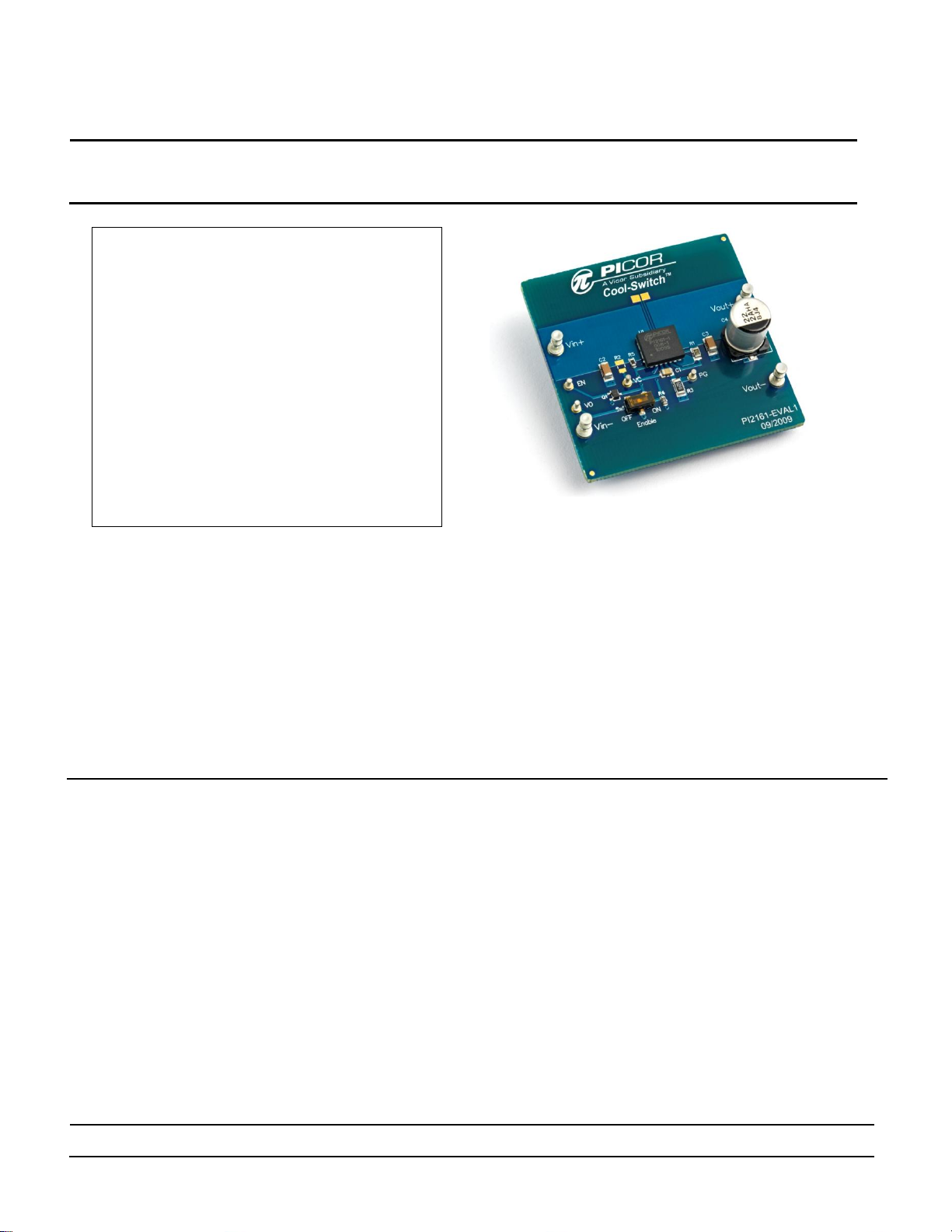
PI2161-EVAL1 Evaluation Board featuring
the Cool-Switch PI2161 Full-Function Load
Disconnect Switch.
The PI2161-EVAL1 Evaluation Board is intended to
acquaint the user with the benefits and features of the
PI2161 full function Load Disconnect
Switch solution. It is not designed to be installed in enduse equipment.
Please read this document before setting up the
PI2161-EVAL1 Evaluation Board and refer to the
PI2161 product datasheet for device specifications,
functional description and characteristics.
Introduction
The PI2161-EVAL1 allows the user to test the basic
principles and operational characteristics of a Load Switch
function, while also experiencing the benefits and value of
the PI2161 solution. The PI2161-EVAL1 evaluation board is
configured to be installed between the input power source
and the load. PI2161 is capable of up to 12A, and is
suitable for a bus voltage up to 48V.
The PI2161-EVAL1 evaluation board is designed with an
optimized PCB layout and component placement to
represent a realistic high density final design for an
embedded Load Switch solution for 48V BUS applications
requiring up to 12A. This evaluation board is intended as
an easy and simple way to test the electrical and thermal
During operation, the power devices and surrounding
structures can be operated safely at high temperatures.
Remove power and use caution when connecting
and disconnecting test probes and interface lines to
avoid inadvertent short circuits and contact with hot
surfaces.
When testing electronic products always use
approved safety glasses. Follow good laboratory
practice and procedures.
performance of the PI2161 Full-Function Load Switch
solution.
Both dynamic and steady state testing of the PI2161 can be
completed on the PI2161-EVAL1 evaluation board, in
addition to using the key features of the product. Dynamic
testing can be completed under a variety of system level
fault conditions to check for response time to faults.
This document provides basic instructions for initial startup and configuration of the evaluation board. Further
information on the functionality of the PI2161 can be
found in the PI2161 product datasheet.
Page 2
Picor Corporation • picorpower.com
PI2161-EVAL1 User Guide Rev. 1.0 Page 2 of 8
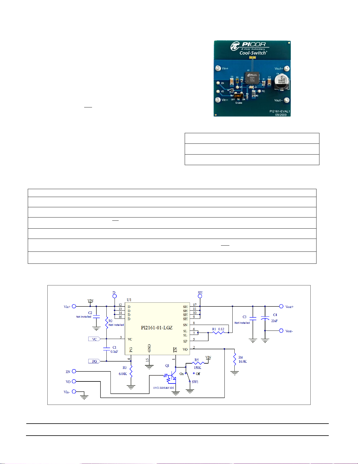
Figure 1: PI2161-EVAL1 Evaluation Board (1.8” x 1.8”)
Terminals Absolute Maximum Rating
Vin+
60V/12Adc
Vout+
60V/12Adc
EN, VO
-0.3V to 17.3V / 10mA
Terminal
Description
Vin+
Power source Input: or bus input designed to accommodate up to 12A continuous current.
Vin-
Input Ground: Connect to the power source low side.
EN
Enable input: Inverse of , set SW1 to Off position when EN input is used
Vout+
Output: Connect to the load high side.
VO
PI2161 Load Status pin: When the internal MOSFET gate is enabled
Vout-
Output Ground: Connect to the load low side.
Figure 2: PI2161-EVAL1 Evaluation Board schematic.
PI2161 Product Description
The Cool-Switch® PI2161 is a complete full-function Load
Disconnect Switch solution for medium voltage
applications with a high-speed electronic circuit breaker
and a very low on-state resistance MOSFET. It is
designed to protect an input power bus from output load
fault conditions. The PI2161 Cool-Switch solution is
offered in an extremely small, thermally enhanced 7mm x
8mm LGA package. The PI2161 enables an extremely low
power loss solution with fast dynamic response to an
over current fault or high conditions. The PI2161
senses a small portion of the total MOSFET current and
has a low voltage threshold allowing the use of low
power sense resistors.
Figure 1, shows a photo of the PI2161-EVAL1 evaluation
board with one load disconnect switch PI2161 SiP. The
board is built with options and features that enable the
user to fully explore the capabilities of the PI2161 Load
Disconnect Switch.
Table 1: PI2161-EVAL1 Evaluation Board Terminals Description Sc
Page 3

Picor Corporation • picorpower.com
PI2161-EVAL1 User Guide Rev. 1.0 Page 3 of 8
Item
QTY
Ref.
Designator
Value/Part NO.
Description
Footprint
Manufacturer
1 1 C1
0.1μF
MLCC Capacitor, X7R, 0.1μF,50V
0805
2 2 C2, C3
1μF
MLCC Capacitor, X7R, 1μF,50V
1206
3 1
C4
22μF
ELEC Capacitor, 22μF,100V
4 2
EN, VO
1528
Turret Test point
TURRET - 1528
Keystone Electronics
5
4
Vin+, Vin-,
Vout+, Vout-
1502
Turret Test point
TURRET - 1502
Keystone Electronics
6 1 Q1
DTC114EUAT106
Transistor, Digital NPN,50V
SOT-323
Rohm Semiconductor
7
1
R1
120mΩ
Resistor, 0.12Ω,1%,0.25W
0805
8 R2
Not installed
Resistor
0805
9
1
R3
6.04kΩ
Resistor,6.04K,1%,0.25W
1206
10
1
R4
16.9kΩ
Resistor,16.9K,1%,0.1W
0603
11
1
R5
150kΩ
Resistor,150K,1%,0.1W
0603
12 1 SW1
Switch
SW SPDT SM
CAS-120
13 1 U1
PI2161-01-LGIZ
Picor Cool-Switch Controller IC
7mmx8mm 17-pin
LGA SiP
PICOR
Ref. Designator
Value/Part NO.
Functional Description
C1
0.1μF
VC Bypass Capacitor
C2, C3
Not installed
Snubber to reduce high voltage noise after disconnect due to high current short.
Recommended value 1μF.
C4
22μF
Output Electrolytic Capacitor
Q1
DTC114EUAT106
PI2161 enable inverting polarity
R1
120mΩ
Current sense resistor
R2
Not installed
Optional high side bias resistor.
R3
6.04kΩ
Low side bias resistor (RPG)
R4
16.9kΩ
VO voltage divider. When the internal MOSFET gate is enabled
R5
150kΩ
pin pull-up resistor.
SW1
Switch
Output Enable/Disable switch
U1
PI2161-01-LGIZ
Full-Function Load Disconnect Switch Solution.
Table 2: PI2161-EVAL1 Evaluation Board Bill of Materials
Table 3: Component functional description
Page 4

Picor Corporation • picorpower.com
PI2161-EVAL1 User Guide Rev. 1.0 Page 4 of 8
40 50 60 70 80 90 100 110 120 130 140 150 160 170 180 190 200
8
10
12
14
16
18
20
22
24
26
28
30
32
Sense Resistor [mΩ]
Forward Overcurrent Trip [A]
Minimum Current trip [V
OC-THL
= 63mV; θ
J-A
= 125°C]
[V
OC-THL
= 63mV; θ
J-A
= 25°C]
Typical Current trip [V
OC-THL
= 70mV; θ
J-A
= 25°C]
Maximum Current trip [V
OC-THL
= 77mV; θ
J-A
= 25°C]
Test Procedure:
Initial Test Set Up
PI2161-EVAL1 is configured for 48V ±10% input bus. The
current limit is set by the sense resistor R1. The sense
resistor is selected (120mΩ) for minimum worst case trip
current of 11.5A at 125°C.
Baseline Test Procedure – PI2161 (Refer to Figure 4)
1. Recommended Material
1.1. Material Needed-Picor supplied
1.1.1. PI2161-EVAL1
1.1.2. PI2161 Product Datasheet
1.2. Recommended Users Supplied Equipment
1.2.1. One DC power supply: 0-60V; 15A.
1.2.2. One low power logic voltage power supply
1.2.3. Load: electronic Load, Power resistors or
actual load.
1.2.4. Multimeter.
1.2.5. Oscilloscope.
1.2.6. Appropriately sized interconnect cables.
1.2.7. Safety glasses.
Before initial power-up follow these steps to configure
the evaluation board for specific end application
requirement:
2. Sense resistor (Rs) selection
2.1. In a typical load switch application the sense
resistor (Rs), R1 in the PI2161-EVAL1, is selected
based on a minimum trip current to allow
maximum normal load current without
interruption. The sense resistor value can be
determined from Overcurrent trip vs. sense
resistor chart in Figure 3:
Please refer to PI2161 Datasheet for more details on
how to calculate the sense resistor value verses trip
current.
Note: Make sure that output capacitor inrush current is
less than two times the minimum set trip current.
Output capacitor inrush current is function of the
output capacitor value and output voltage rise time.
Figure 3: PI2161 Overcurrent trip vs. sense resistor chart
Page 5

Picor Corporation • picorpower.com
PI2161-EVAL1 User Guide Rev. 1.0 Page 5 of 8
Figure 4: Layout configuration for a typical Load Disconnect Switch application test using PI2161.
3. Control Circuitry Bias:
As described in the Functional Description section in
PI2161 datasheet; in a floating application it is
required to place low side bias resistor RPG (R3)
between the PG pin and system ground. RPG creates
an offset voltage at the PG pin to regulate VC with
respect to PG when the MOSFET is enabled.
The RPG resistor can be calculated using the following
expression:
Please refer to application section in the PI2161
datasheet for more details.
4. Enabling PI2161: PI2161-EVAL1 is set with two
enabling options.
4.1. Mechanical switch (SW1) option. Moving SW1
knob to On position to enable (turn on MOSFET
if conditions are met) PI2161, or moving SW1
knob to Off position to disable (turn off
MOSFET) PI2161.
4.2. Logic input terminal (EN) option: to use this
option slide WS1 knob to Off position. Apply
logic high voltage (>2V) to enable PI2161 and
logic low (<1V) to disable PI2161.
5. Hook Up of the Evaluation Board
5.1. Connect the positive terminal of PS1 power
supply to Vin+. Connect the ground terminal of
PS1 to Vin-. Set the power supply to 48V. Keep
PS1 output disabled, off.
5.2. Connect the electronic load to the output
between Vout+ and Vout-. Set the load current
to 5A
5.3. Position SW1 knob to On
5.4. Enable (turn on) PS1 power supply output.
5.5. Turn on the electronic load
5.6. Verify that the load voltage (Vout) is few
millivolts below 48V. This verifies that the
PI2161 MOSFET is in conduction mode.
5.7. Measure VO with respect to Vin-, it should be
10% of Vout, 4.5V.
5.8. Slide SW1 to Off position to disable the output.
5.9. Verify that the load voltage (Vout) is off, about
0V. This verifies that the M1 MOSFET is turned
off. VO voltage should be at 0V.
6. Over current trip point:
PI2161 has a very fast response (120ns) to over current
fault condition. Measuring a fast disconnect after high
current buildup requires attention to the test set-up. Before
proceeding, consider the following:
6.1. To emulate a real application, the BUS supply for
this test should have a solid output source such
as a DC-DC converter that supply’s high current
and can be connected very close to the
evaluation board. This will reduce stray parasitic
inductance. Or use the prospective supply
sources of the end application where the PI2161
will be used. Typical bench power supplies have
slow response to output load change. In this test
when the output load is shorted, a high pulse of
Page 6

Picor Corporation • picorpower.com
PI2161-EVAL1 User Guide Rev. 1.0 Page 6 of 8
94.4ns
Set Trip Current
at 10.5A
(Rs=200mΩ)
Input Current (5A/div)
Output Voltage [SH] (5V/div)
PG pin (5V/div)
Input Voltage [D] (5V/div)
Start Turn
off & latch
MOSFET
Avalanche
At 69V
120.4ns
Output Voltage [SH] (5V/div)
Input Current (5A/div)
Input Voltage [D] (5V/div)
PG pin (5V/div)
Turn off
& latch
Test Setup:
DUT: PI2161-EVAL1
Vin = 45V
Output Load = 1.5A
Rs (R1) = 200mΩ
First applied slow ramping load
current and determined the trip
current: 10.5A
Test: Apply output short
PI2161 was enabled and load
current is at 1.5A, then shorted
Vout+ to Vout- with a MOSFET.
The current ramped at 230A/μs.
PI2161 turned the output off at
load current of 33A, by pulling
the MOSFET gate low and latch
it low.
PI2161 internal MOSFET starts to
turn off 94ns after the current
reach the trip point (10.5A). And
current is sourced from the power supply and
its output voltage will drop, but when the
MOSFET disconnects the load (shorted) from
the source, the bench power supply may
produce high output voltage with high current
capability that may damage the device under
test.
If a bench power supply has to be used, or there
is some wiring inter connection between PI2161EVAL1 input (Vin+ and Vin-) and the power
source, add a large electrolytic capacitor
between Vin+ and Vin- terminals to reduce
power source high voltage transient after load
disconnect.
6.2. Place the scope probes very close to PI2161 D
pin and SH pin to measure Vout and Vin, and
make sure that the scope ground leads are very
short.
6.3. Current trip point:
To find the exact current trip level, repeat steps
5.1 to 5.9 and then increment the load current
slowly. The current can be monitored by a
current probe placed at the unit input or by
reading the current display at the power supply
(PS1) or at the electronic load display. The
actual trip current is the current right before the
PI2161 turns the output off, VO output will go to
0V to indicate that the output is disconnect from
the source.
After PI2161 turns the output off by pulling the
MOSFET gate low, it will hold the MOSFET in an
off condition until it is reset.
6.4. Device Reset:
To reset PI2161 after a fault (high load current),
recycle PI2161 by sliding SW1 knob to Off
position and then slide the knob back to On
position.
6.5. Output short test
Enable PS1 and then apply a short at the load
(Vout). The short can be applied electronically
using the electronic load, a MOSFET connected
between Vout+ and Vout- or simply by connecting
Vout+ to Vout-. Then measure the response time
between when the output current reached the
set trip point and when PI2161 disconnect the
load. An example for PI2161 response time to an
output short circuit is shown in Figure 5.
Figure 5: Plot of PI2161 response time to a forward over-current condition
Page 7

Picor Corporation • picorpower.com
PI2161-EVAL1 User Guide Rev. 1.0 Page 7 of 8
Figure 6: PI2161-EVAL1 layout top layer. Scale 2.0:1
Figure 7: PI2161-EVAL1 layout bottom layer 2. Scale 2.0:1
Figure 8: PI2161-EVAL1 evaluation board mechanical drawing.
Page 8

Picor Corporation • picorpower.com
PI2161-EVAL1 User Guide Rev. 1.0 Page 8 of 8
Warranty
Vicor products are guaranteed for two years from date of shipment against defects in material or
workmanship when in normal use and service. This warranty does not extend to products subjected to
misuse, accident, or improper application or maintenance. Vicor shall not be liable for collateral or
consequential damage. This warranty is extended to the original purchaser only.
EXCEPT FOR THE FOREGOING EXPRESS WARRANTY, VICOR MAKES NO WARRANTY, EXPRESS OR
LIMITED, INCLUDING, BUT NOT LIMITED TO, THE WARRANTY OF MERCHANTABILITY OR FITNESS FOR A
PARTICULAR PURPOSE.
Vicor will repair or replace defective products in accordance with its own best judgment. For service
under this warranty, the buyer must contact Vicor to obtain a Return Material Authorization (RMA)
number and shipping instructions. Products returned without prior authorization will be returned to the
buyer. The buyer will pay all charges incurred in returning the product to the factory. Vicor will pay all
reshipment charges if the product was defective within the terms of this warranty.
Information published by Vicor has been carefully checked and is believed to be accurate; however, no
responsibility is assumed for inaccuracies. Vicor reserves the right to make changes to any products
without further notice to improve reliability, function, or design. Vicor does not assume any liability
arising out of the application or use of any product or circuit; neither does it convey any license under
its patent rights nor the rights of others. Vicor general policy does not recommend the use of its
components in life support applications wherein a failure or malfunction may directly threaten life or
injury. Per Vicor Terms and Conditions of Sale, the user of Vicor components in life support applications
assumes all risks of such use and indemnifies Vicor against all damages.
Vicor’s comprehensive line of power solutions includes high density AC-DC and DC-DC modules and
accessory components, fully configurable AC-DC and DC-DC power supplies, and complete custom
power systems.
Information furnished by Vicor is believed to be accurate and reliable. However, no responsibility is
assumed by Vicor for its use. Vicor components are not designed to be used in applications, such as life
support systems, wherein a failure or malfunction could result in injury or death. All sales are subject to
Vicor’s Terms and Conditions of Sale, which are available upon request.
Specifications are subject to change without notice.
Vicor Corporation Picor Corporation
25 Frontage Road 51 Industrial Drive
Andover, MA 01810 North Smithfield, RI 02896
USA USA
Customer Service: custserv@vicorpower.com
Technical Support: apps@vicorpower.com
Tel: 800-735-6200
Fax: 978-475-6715
 Loading...