

Page 1
Picor Corporation • picorpower.com
PI2007-EVAL2 User Guide Rev. 1.1 Page 1 of 9
PI2007-EVAL2 12V/15A High Side Active ORing
Evaluation Board User Guide
Content Page
Introduction ......................................................... 1
Product Description ............................................ 2
Schematic ........................................................... 3
Bill of Material...................................................... 4
Test Procedure .................................................... 5
Recommended Material ...................................... 5
PCB Layout ......................................................... 8
Mechanical Drawing ............................................ 8
PI2007-EVAL2
Cool-ORing® Series
Cool-ORing® Series
PI2007-EVAL2 Evaluation Board
featuring the Cool-ORing PI2007
Active ORing controller.
The PI2007-EVAL2 Evaluation Board is intended to
acquaint the user with the benefits and features of the
Cool-ORing® PI2007 full function Active ORing solution.
It is not designed to be installed in end-use equipment.
Please read this document before setting up the
PI2007-EVAL2 Evaluation Board and refer to the
PI2007 product datasheet for device specifications,
functional description and characteristics.
Introduction
The PI2007-EVAL2 allows the user to test the basic
principle and operational characteristics of an Active ORing
function in a redundant power architecture, while also
experiencing the benefits and value of the PI2007 solution
versus conventional Active ORing solutions. The PI2007EVAL2 evaluation board is configured to receive two
independent power source inputs, per a typical redundant
power architecture, through two Active ORing channels
that are combined to form a redundant power output.
Each channel contains a PI2007 controller and a 25V Nchannel power MOSFET. The MOSFET foot print can take
an SO-8 or Power SO-8 MOSFET package. Each channel is
capable of up to 15A.
The PI2007-EVAL2 evaluation board is designed with
optimized PCB layout and component placement to
represent a realistic high density final design for an
During operation, the power devices and surrounding
structures can be operated safely at high temperatures.
Remove power and use caution when connecting
and disconnecting test probes and interface lines to
avoid inadvertent short circuits and contact with hot
surfaces.
When testing electronic products always use
approved safety glasses. Follow good laboratory
practice and procedures.
embedded high side Active ORing solution for 12V Bus
(10V to 14V) applications requiring up to 15A. This
evaluation board is intended as an easy and simple way to
test the electrical and thermal performance of the PI2007
Active ORing controller.
Both dynamic and steady state testing of the PI2007 can be
completed on the PI2007-EVAL2 evaluation board, in
addition to using the key features of the product. Dynamic
testing can be completed under a variety of system level
fault conditions to check for response time to faults.
This document provides basic instructions for initial startup and configuration of the evaluation board. Further
information on the functionality of the PI2007 can be
found in the PI2007 product data sheet.
Page 2
Picor Corporation • picorpower.com
PI2007-EVAL2 User Guide Rev. 1.1 Page 2 of 9
Cool-ORing® PI2007 Product Description
Terminals Maximum Rating
Vin1, Vin2,
25V/15A
Vout
25V/30A
1, 2
-0.3V to 17.3V / 10mA
VL1, VL2 (R5=R6=1.5kΩ)*
5.5V
* VL1, VL2 voltage can be higher than 5.5V, but R5 and R6
values have to be increased to accommodate the LEDs
Terminal
Description
Vin1
Power source Input #1 or bus input designed to accommodate up to 15A continuous current.
Vin2
Power source Input #2 or bus input designed to accommodate up to 15A continuous current.
1
PI2007 (U1) Fault pin: Monitors U1 fault conditions.
2
PI2007 (U2) Fault pin: Monitors U2 fault conditions.
VC1
PI2007 (U1) VC input: Leave this pin unconnected unless an alternative controller bias voltage.
VC2
PI2007 (U2) VC input: Leave this pin unconnected unless an alternative controller bias voltage.
VL1
Fault pin 1 LED supply
VL2
Fault pin 2 LED supply
Vout
Output: Q1 and Q2 MOSFETs drain connection, connect to the load high side.
Rtn
Return Connection: Three Rtn connections are available and are connected to a common point, the Ground plane. Input
supplies Vin1, Vin2, and the output load at Vout should all be connected to their respective local Rtn connection.
The Cool-ORing PI2007 with an external industry
standard 25V N-channel MOSFET provides a complete
Active ORing solution designed for use in 12V Bus (10V to
14V) redundant power system architectures. The PI2007
controller with an N-channel MOSFET enables extremely
low power loss with fast dynamic response to fault
conditions, critical for high availability systems.
The PI2007 controller with a low R
N-channel
DS(on)
MOSFET provides very high efficiency and low power loss
during steady state operation. The PI2007 controller
provides an active low fault flag output to the system
during excessive forward current or reverse current, or
under VC under voltage condition.
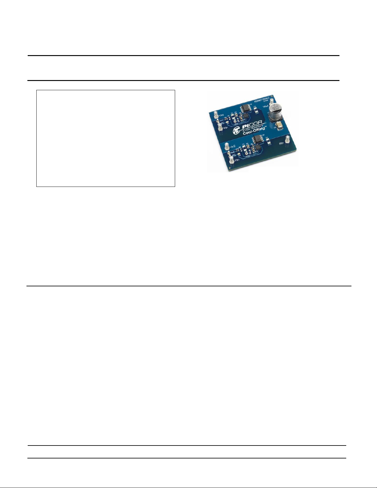
Figure 1 shows a photo of the PI2007-EVAL2 evaluation
board, with two PI2007 controllers and two N-channel
MOSFET used to form the two Active ORing channels. The
board is built with two identical Active ORing circuits with
options and features that enable the user to fully explore
the capabilities of the PI2007 Active ORing controller.
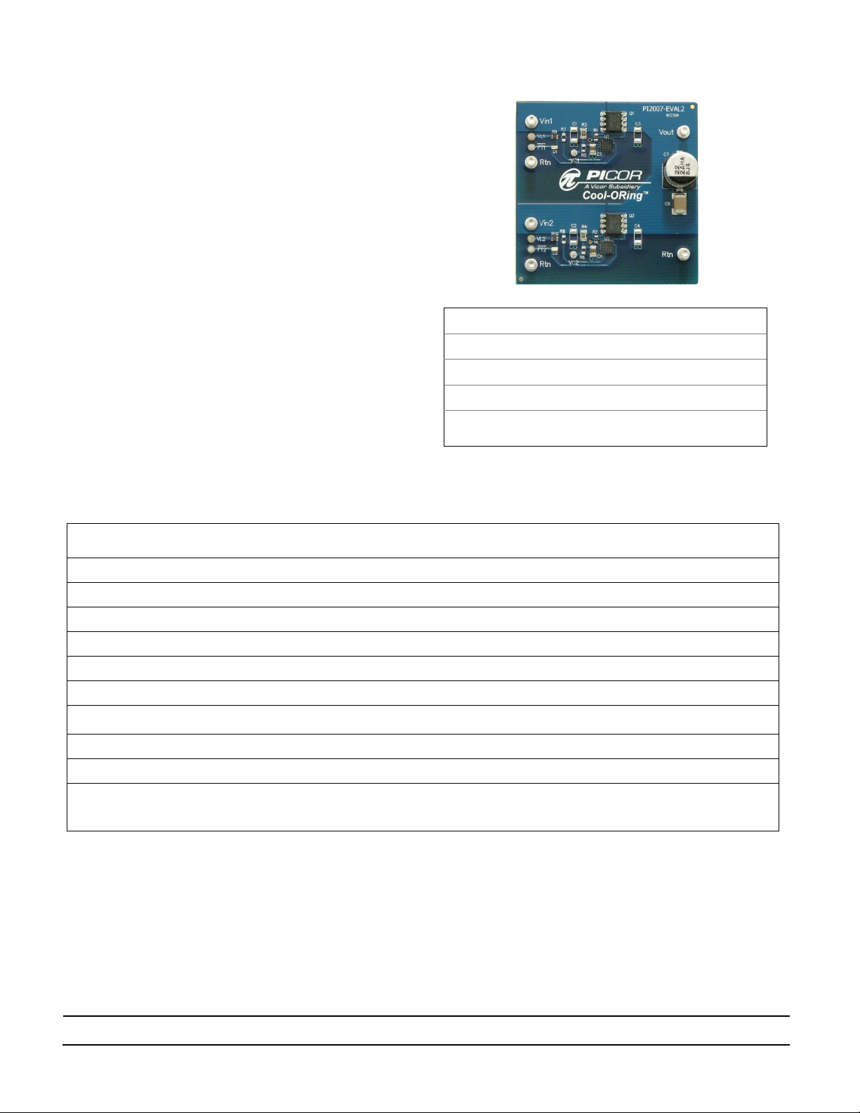
Figure 1: PI2007-EVAL2 Evaluation Board (1.8” x 1.8”)
Table 1: PI2007-EVAL2 Evaluation Board Terminals Description
Page 3
Picor Corporation • picorpower.com
PI2007-EVAL2 User Guide Rev. 1.1 Page 3 of 9
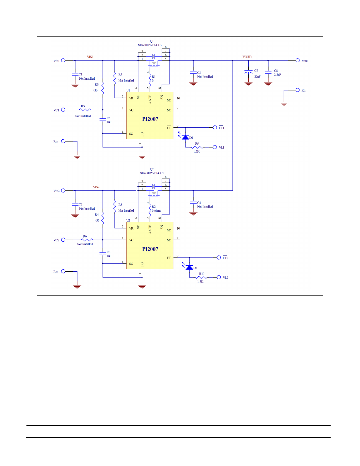
Schematic
Figure 2: PI2007-EVAL2 Evaluation Board schematic.
Page 4

Picor Corporation • picorpower.com
PI2007-EVAL2 User Guide Rev. 1.1 Page 4 of 9
Bill of Material
Item
QTY
Ref. Designator
Value/Part NO.
Description
Footprint
Manufacturer
1 2 C1, C2, C3, C4
Not Installed
MLCC Capacitor, X7R, 1uF,50V
1206 2 2 C5, C6
1μF
MLCC Capacitor, X7R, 1uF,50V,
805 3 1 C7
22μF
Electrolytic Capacitor, 22uF,100V
Panasonic _E/F
Panasonic
4 1 C8
Not Installed
MLCC Capacitor, 10uF,25V
1812 5 2 D1, D2
LTST-C191CKT
LED, Red
0603 LED
Lite-On
6
6
1, 2, VC1,
VC2, VL1, VL2
1528
Turret Test point
TURRET - 1528
Keystone
Electronics
7
6
Rtn, Rtn, Rtn, Vin1,
Vin2, Vout
1502
Turret Test point
TURRET - 1502
Keystone
Electronics
8 2 Q1, Q2
SI4630DY-T1-GE3
N-MOSFET,25V,40A
PPAK SO-8
Siliconix
9 1 R1, R2
0Ω
Resistor,0 Ω,1%,0.1W
0603
10 1 R3, R4
430Ω
Resistor,430Ω, 1%, 0.125W
0805
11 1 R5, R6, R7, R8
Not Installed
12 2 R9, R10
1.5K
Resistor,1.5K,1%,0.1W
603
13 2 U1, U2
PI2007-00-QEIG
Picor Cool ORing Controller IC
3x3mm 10L TDFN
PICOR
Ref. Designator
Value/Part NO.
Functional Description
C1, C2, C3, C4
Not Installed
Snubber to reduce voltage ringing when the device turns off
Add the capacitors if a long harnesses are used to connect the power source or load to the
board.
C5, C6
1uF
VC Bypass Capacitor
C7
22uF
Output (Load) Capacitor
C8
Not Installed
Output (Load) Capacitor, this capacitor can be installed if instead of C7 if the user requires a
ceramic load capacitor, 1812 package can accommodate a high ceramic capacitors value at
25V rating.
D1, D2
LTST-C191CKT
To indicate a fault exists when it is on
Q1, Q2
SI4630DY-T1-GE3
ORing switch
R1, R2
0Ω
Gate resistor, optional to slow gate turn off time, higher value resistor will reduce gate pull
down peak current
R3, R4
430Ω
VC bias resistor
R5, R6,
Not Installed
Optional to use PI2007 external VC bias voltage, removing R3 and R4 when external bias
voltage is used.
R7, R8
Not Installed
Optional to use PI2007 internal VC bias resistor (VR) by placing 0Ω resistor and removing R3
and R4
R15, R16
1.5K
LED current limit resistor, selected to operate at 3.3V and 5.0V logic voltage. Replace R15
and R16 with the proper resistor value for different logic voltage.
U1, U2
PI2007
Cool ORing Controller
Table 2: PI2007-EVAL2 Evaluation Board Bill of Materials
Table 3: Component functional description
Page 5
Picor Corporation • picorpower.com
PI2007-EVAL2 User Guide Rev. 1.1 Page 5 of 9
Test Procedure:
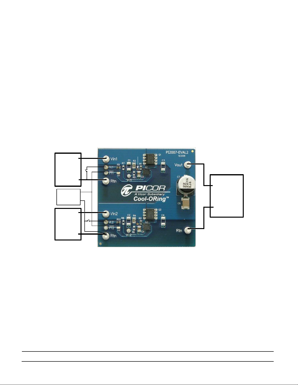
Figure 3: Layout configuration for a typical redundant power application using PI2007.
DC
Electronic
Load
PS1
-
PS2
+
-
+
-
0-20V/20A
30A
0-20V/20A
PS3
+
-
12V/100mA
Logic PS
+
Gate
Initial Test Set Up
PI2007-EVAL2 is designed with two bias circuit
options, bias via 1% external resistor (R3 and R4) or via
internal resistor (VR input). R3 and R4 resistors are
installed (430Ω, 1%).
Baseline Test Procedure – PI2007 (Refer to Figure 3)
1. Recommended Material
1.1. Material Needed-Picor supplied
1.1.1. PI2007-EVAL2
1.1.2. PI2007 Product Datasheet
1.2. Recommended Users Supplied Equipment
1.2.1. Two DC power supplies: 0-20V; 20A each.
1.2.2. One low power logic voltage power supply
1.2.3. Load: electronic Load, Power resistors or
actual load.
1.2.4. Multimeter.
1.2.5. Oscilloscope.
1.2.6. Appropriately sized interconnect cables.
1.2.7. Safety glasses.
Page 6

Picor Corporation • picorpower.com
PI2007-EVAL2 User Guide Rev. 1.1 Page 6 of 9
Before initial power-up follow these steps to configure
the evaluation board for specific end application
requirement:
Note that PI2007 will not turn off the MOSFET unless it
senses current in the reverse direction through the
MOSFET. This means that if both input power source
are turned on and both MOSFET are in on condition,
then one off the power source is turned off, the
associated PI2007 will not turn off the MOSFET unless
the power source sinks current from the output when it
turns off and cause a reverse current in the MOSFET that
generates negative voltage equal or greater than 6mV.
2. Control Circuitry Bias:
PI2007 control circuitry and the gate driver for the
MOSFET are biased through the VC pin. An internal
regulator clamps VC pin voltage with respect to PG
pin (V
) to 11.7V typically. In a 12V application
VC-PG
the input voltage can vary between 10V and 14V
which is higher than the VC clamp voltage. A bias
resistor between VC pin and input voltage is required
to accommodate VC clamp.
3.6. Enable (turn on) PS3 power supply output.
3.7. Turn on the electronic load.
3.8. Verify that the load voltage (Vout) is few
millivolts below 12V. This verifies that the Q1
MOSFET is in conduction mode.
3.9. Verify that Vin2 is low. This verifies that Q2
MOSFET is off.
3.10. Enable (turn on) PS2 output.
3.11. Verify that both PS1 and PS2 are sharing load
current evenly by looking at the supply current.
Power supplies output may need adjustment to
set current sharing between the supplies.
3.12. Disable (turn off) PS1, PS2, and PS3 outputs.
3.13. Enable (turn on) PS2 output then Enable and PS3
outputs.
3.14. Verify that Vout is few millivolts below 12V. This
verifies that the MOSFET Q2 is in conduction
mode.
3.15. D2 should be off. This verifies that there is no
fault condition.
PI2007-EVAL2 has two options for the bias resistor. A
420Ω internal resistor connected between VC pin
and VR pin, or 430Ω 1% external resistor (R3 and R4).
R3 and R4 installed in PI2007-EVAL2. If the internal
resistor is desired for the test, remove R3 and R4,
and install 0Ω resistor (jumper) for R7 and R8 to
connect PI2007 VR pin to its input.
3. Hook Up of the Evaluation Board
3.1. Connect the positive terminal of PS1 power
supply to Vin1. Connect the ground terminal of
PS1 to its local Rtn. Set the power supply to
12V. Keep PS1 output disabled, off.
3.2. Connect the positive terminal of PS2 power
supply to Vin2. Connect the ground terminal of
PS2 to its local Rtn. Set the power supply to
12V. Keep PS2 output disabled, off.
3.3. Connect the logic power supply PS3 positive
terminal to VL1 and VL2. Connect the ground
terminal of this power supply to a Rtn terminal.
Set the power supply to the desired logic
voltage level, 3.3V or 5V. Keep PS3 output
disabled, off.
3.4. Connect the electronic load to the output
between Vout and its local Rtn. Set the load
current to 5A.
3.5. Enable (turn on) PS1 power supply output.
3.16. Verify that Vin1 is low. This verifies that the
MOSFET (Q1) is off.
4. Input short circuit test:
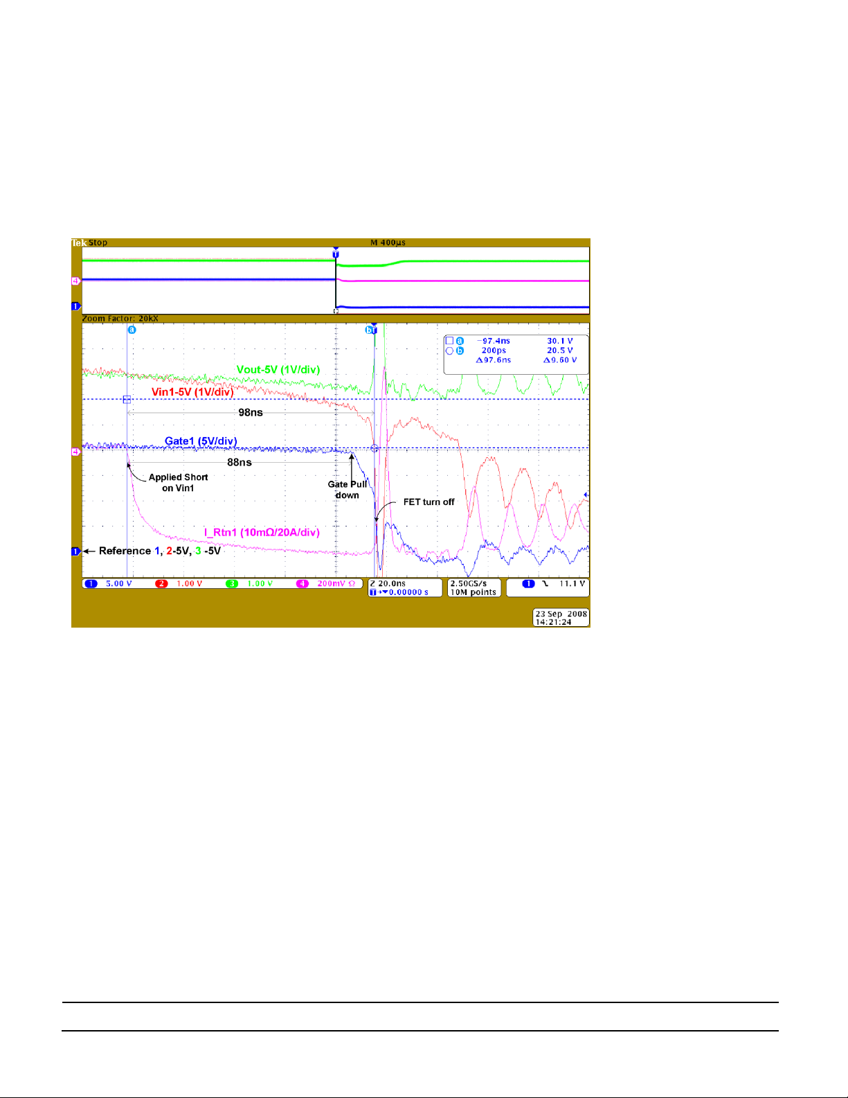
PI2007 has a very fast response (80ns) to a reverse current
(Input short) fault condition. Measuring a short period
event requires attention to the test set-up. Before
proceeding, consider the following:
4.1. To emulate a real application, the BUS supplies
for this test should have a solid output source
such as a DC-DC converter that supplies high
current and can be connected very close to the
evaluation board to reduce stray parasitic
inductance. Or use the prospective supply
sources of the end application where the PI2007
will be used. Typical bench power supplies have
slow response to output load change. In this test
when the power supply output is shorted and
then released, the bench power supply may
produce high output voltage with high current
capability that may damage the device under
test.
4.2. Do not install Input capacitors (C1 and/or C2) in
this test.
4.3. Output capacitor (C7) should be installed.
4.4. Place the scope probes very close to the MOSFET
drain and source to measure Vout and Vin, and
Page 7
Picor Corporation • picorpower.com
PI2007-EVAL2 User Guide Rev. 1.1 Page 7 of 9
make sure that the scope ground leads are very
Test Setup:
DUT: PI2007-EVAL2
Vin1 = 12V
Vin2 = 12V
Output Load = 6A
Test:
Both input sources are
turned on and sharing the
load current, then applied a
short for 1ms with fast turn
on 1mΩ MOSFET between
Vin1 and Rtn.
Test purpose:
To show the PI2007 response
to a fault condition, where
the output of the input
source is shorted or tried to
source current from the load
(Vout)
short. You may use a close by ground pad for
the scope probe return, such as C1, C2, C3 and
C4 Rtn pads.
4.5. Apply a short at one of the inputs (Vin1 or Vin2)
when both controllers (U1 and U2) are on, PS1
and PS2 are enabled. The short can be applied
electronically using a MOSFET connected
between Vin and Rtn or simply by connecting Vin
to Rtn. Then measure the response time
between when the short being applied and the
MOSFET being disconnected (or turned off). An
example for PI2007 response time to an input
short circuit is shown in Figure 4.
Figure 4: Plot of PI2007 response time to reverse current detection
Page 8

Picor Corporation • picorpower.com
PI2007-EVAL2 User Guide Rev. 1.1 Page 8 of 9
PCB Layout
Figure 5: PI2007-EVAL2 layout top layer. Scale 2.0:1
Figure 6: PI2007-EVAL2 layout bottom layer 2. Scale 2.0:1
Mechanical Drawing
Figure 7: PI2007-EVAL2 evaluation board mechanical drawing
Page 9

Picor Corporation • picorpower.com
PI2007-EVAL2 User Guide Rev. 1.1 Page 9 of 9
Warranty
Vicor products are guaranteed for two years from date of shipment against defects in material or
workmanship when in normal use and service. This warranty does not extend to products subjected to
misuse, accident, or improper application or maintenance. Vicor shall not be liable for collateral or
consequential damage. This warranty is extended to the original purchaser only.
EXCEPT FOR THE FOREGOING EXPRESS WARRANTY, VICOR MAKES NO WARRANTY, EXPRESS OR LIMITED,
INCLUDING, BUT NOT LIMITED TO, THE WARRANTY OF MERCHANTABILITY OR FITNESS FOR A
PARTICULAR PURPOSE.
Vicor will repair or replace defective products in accordance with its own best judgment. For service
under this warranty, the buyer must contact Vicor to obtain a Return Material Authorization (RMA)
number and shipping instructions. Products returned without prior authorization will be returned to the
buyer. The buyer will pay all charges incurred in returning the product to the factory. Vicor will pay all
reshipment charges if the product was defective within the terms of this warranty.
Information published by Vicor has been carefully checked and is believed to be accurate; however, no
responsibility is assumed for inaccuracies. Vicor reserves the right to make changes to any products
without further notice to improve reliability, function, or design. Vicor does not assume any liability
arising out of the application or use of any product or circuit; neither does it convey any license under its
patent rights nor the rights of others. Vicor general policy does not recommend the use of its
components in life support applications wherein a failure or malfunction may directly threaten life or
injury. Per Vicor Terms and Conditions of Sale, the user of Vicor components in life support applications
assumes all risks of such use and indemnifies Vicor against all damages.
Vicor’s comprehensive line of power solutions includes high density AC-DC and DC-DC modules and
accessory components, fully configurable AC-DC and DC-DC power supplies, and complete custom
power systems.
Information furnished by Vicor is believed to be accurate and reliable. However, no responsibility is
assumed by Vicor for its use. Vicor components are not designed to be used in applications, such as life
support systems, wherein a failure or malfunction could result in injury or death. All sales are subject to
Vicor’s Terms and Conditions of Sale, which are available upon request.
Specifications are subject to change without notice.
Vicor Corporation Picor Corporation
25 Frontage Road 51 Industrial Drive
Andover, MA 01810 North Smithfield, RI 02896
USA USA
Customer Service: custserv@vicorpower.com
Technical Support: apps@vicorpower.com
Tel: 800-735-6200
Fax: 978-475-6715
 Loading...