

Page 1
USER GUIDE | UG:115
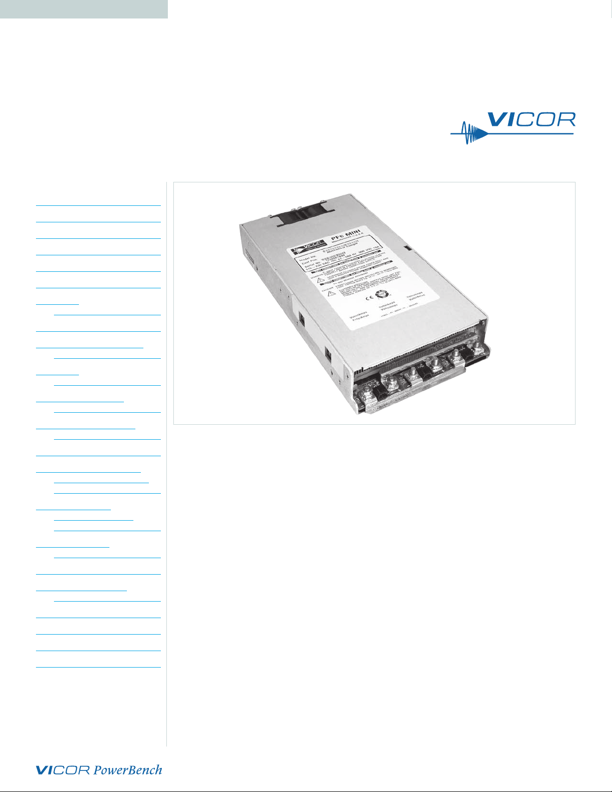
PFC Mini™
Power Factor Corrected AC-DC Switcher
Contents Page
Overview 1
Standard Features 2
Optional Features 2
Mechanical Considerations 2
PFC Mini Dos and Don’ts 3
Technical Description 3
PFC Mini™
Configuration Layout 5
Part Numbering 6
PFC MegaPAC Quick Install
Instructions 7
PFC Mini™
Mechanical Drawing 9
Output Connectors for
PFC Mini™ 10
PFC Mini™ Connector Kit
(19-130047) Listing 11
Interface Connections 11
Enable / Disable Control of
Maxi, Mini, Micro Series
Module Arrays 16
Minor Changes for
PFC Mini™ Shipped
October 2005 Onwards 18
PFC Mini™ Output
Power vs. Input Voltage 19
Specifications 20
Current Share Boards –
Optional Feature 23
Low-Leakage Version 26
Low Output Ripple 26
Office Environment Fan 26
Molex Connector Limitation 26
Overview
The PFC Mini is an extremely low-profile 1RU switching power supply that combines the advantages of
power-factor correction and high power density. This guide covers both standard- and rugged-chassis
COTS (MI) versions of the product. The PFC Mini can provide up to six isolated outputs (three slots) and
each slot accommodates the following Vicor DC-DC Converters.
VI/E-200™ and VI/E-J00™ series: one VI/E-200 or two VI/E-J00 converters
Maxi, Mini Micro series: one Maxi, two Mini converters (Micros cannot be used)
The use of these converters give the PFC Mini the inherent power flexibility typical of all Vicor
products. Accepting input voltages of 85 – 264VAC, and 100 – 380VDC, the PFC Mini can provide
up to 1,500 Watts in a package size of 1.72 x 6 x 12.2in [43,6 x 152,4 x 309,9mm]. The PFC Mini is
factory-configured to meet user requirements.
Note: If you have a PFC Mini that shipped from October 2005 onwards, please see Page 18 for more details.
UG:115 Page 1
Page 2

Standard Features
Power factor correction: 0.99 at 115VAC; 0.95 at 230V
Universal input: 85 – 264VAC, 47 – 500Hz, or 100 – 380V
Power output: 1,500W at 230VAC; 800W at 115V
AC
DC
AC
Up to six isolated outputs (three slots)
Fan cooled
Full power to 45°C; half power at 65°C
Conducted EMI:
VI-200™/VI-J00™ series: Maxi, Mini, Micro series:
FCC Class B FCC Class A
EN55022 Class B EN55022 Class A
(certain configurations meet EN55022 Class B)
Harmonic distortion complies with EN61000-3-2
AC Power OK status signal
Autosense (for more information, see Page 8 and Page 13)
Output overcurrent protection on all outputs
Output overvoltage protection (not applicable when using VI-J00)
Output overtemperature limiting (not applicable when using VI-J00)
Ride-through (hold-up) time: >20ms at 1,200W load (nominal line)
Size: 1.72 x 6 x 12.2in [43,6 x 152,4 x 309,9mm]
Safety agency approvals: CE Mark, cTÜVus, UL
(Note: certain MI chassis may not carry all safety certs.)
Optional Features
Extended temperature range output converters
Current share board - see Page 23
RAM™ modules for low noise applications - see Page 26
Connector kit available (#19-130047)
Low leakage available – see Page 26
Office environment fan – see Page 26
MI-chassis-specific options:
Mil-STD-810 for shock and vibration
Mil-STD-704 and -1399 for overvoltage and transients
–40°C Operation
Conformal coating – contact factory
UG:115 Page 2
Page 3

Mechanical Considerations
The PFC Mini™ can be mounted on either of two surfaces using standard 8-32 (4 mm) size screws.
Maximum allowable torque is 4.4in.lbs and the maximum penetration is 0.16in [4mm]. When selecting
a mounting location and orientation, the unit should be positioned so airflow is not restricted. Maintain
a 2in [5,1cm] minimum clearance at both ends of the PFC Mini and route all cables so airflow is not
obstructed. The power supply draws air in at the fan-side/AC-input side and exhausts air out the
load side. If airflow ducting is used, avoid sharp turns that could create back pressure. The fans move
approximately 20CFM of air.
Avoid excessive bending of output power cables after they are connected to the output terminals.
For high-current outputs, use cable ties to support heavy cables and minimize mechanical stress on
connectors. Be careful not to short-out to neighboring outputs. The maximum torque recommended on
output nuts is 10in.lbs.
Avoid applications in which the unit is exposed to excessive shock or vibration levels. In such
applications, a shock-absorbing mount design is required.
PFC Mini Dos and Don’ts
If sense jumpers are removed, do not leave sense lines open (especially if unit does not have
Autosense). Sense lines must be terminated to their respective outputs. Use twisted pair
20 – 22AWG wire when installing remote sense
NEVER disconnect the +OUT and –OUT load wires while the supply is operating as
disconnecting WILL cause damage to the power supply. Ensure load wires connected before
remote sense connected.
To prevent damage to supply, verify polarity of remote-sense connection before turning supply on.
Always turn the power supply off before disconnecting input or output wires.
Do not restrict airflow to the unit. The cooling fan draws air into the unit and forces it out at the
output terminals.
Run the output (+/–) power cables next to each other to minimize inductance.
Do not repair or modify the power supply in any manner. Doing so will void the warranty.
Contact Factory.
Insert proper fault protection at power supply input terminals (i.e., a fuse).
Use proper size wires to avoid overheating and excessive voltage drop.
Output voltages over 60VDC, whether from individual modules or series arrays, are considered
as hazardous secondary outputs under UL60950. Appropriate care must be taken in design
implementation of the supply.
UG:115 Page 3
Page 4
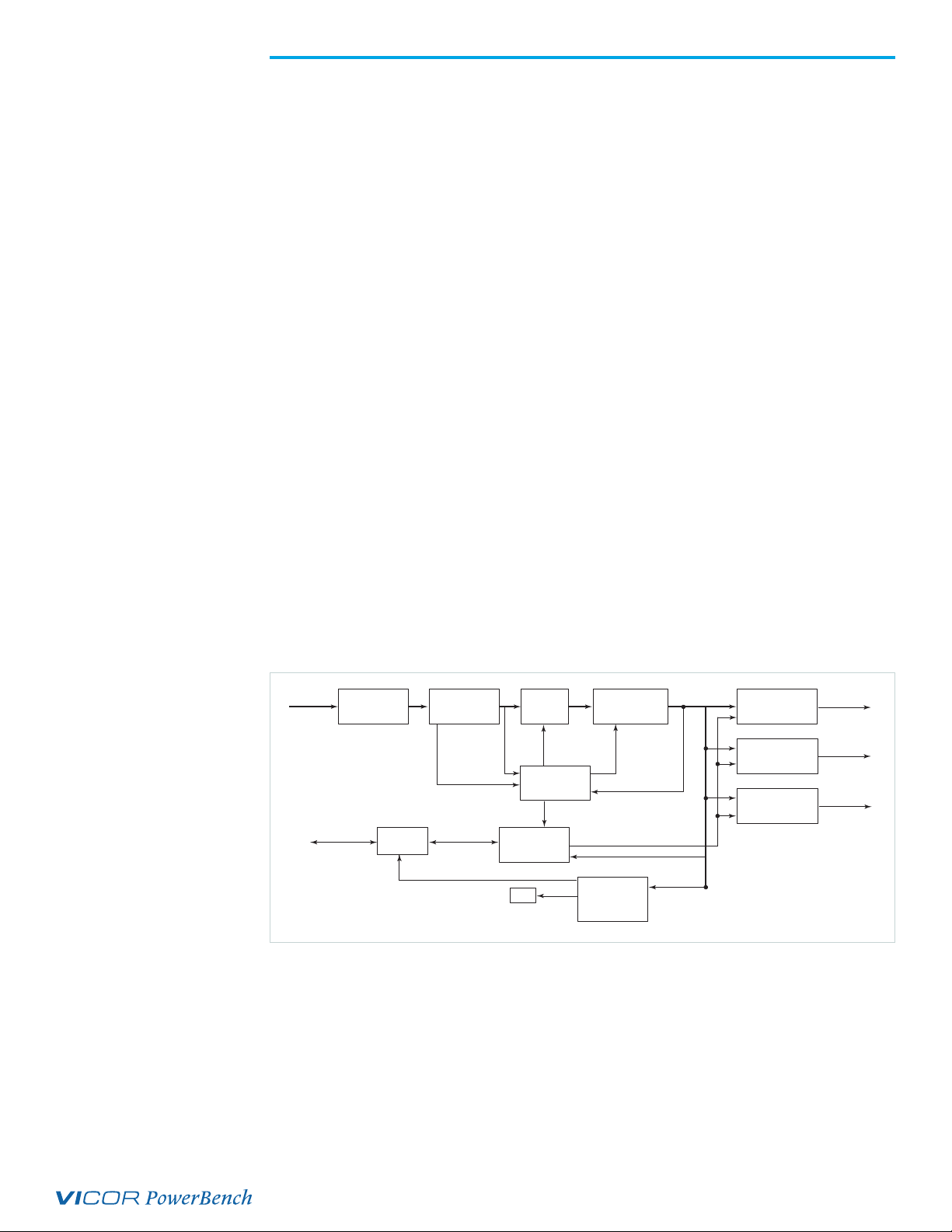
Technical Description
The PFC Mini consists of an offline single-phase, power-factor-corrected front end, EMI filter, cooling
fan, customer interface, associated housekeeping circuits and a selection of Vicor DC-DC converters.
Input AC mains voltage is applied to a terminal block. The input current is passed through an EMI filter
designed to meet conducted noise limit “B” specifications in FCC Part 15 and EN55022, Class B (with
VI-200™/VI-J00™ series modules. If Maxi, Mini, Micro series modules are used, it meets FCC Class A
and EN55022 Class A. (Certain configurations meet Class B).
At start up, inrush current is limited by a PTC thermistor. The PTC is shunted out shortly after initial
power up by a DC bus voltage sense circuit driving a relay. After rectification, the input voltage is
put through a boost converter that keeps the AC input current sinusoidal and synchronized with the
input AC voltage (in compliance with EN61000-3-2). The boost converter delivers a regulated input
to the hold-up capacitors and a high-voltage backplane. The backplane supplies power to the DC-DC
converters that provide the desired low-voltage regulated outputs.
Voltage conversion is achieved by the Vicor family of zero-current switching (ZCS) DC-DC converters.
These are forward converters in which the main switching element switches at zero current. This
patented topology has a number of unique attributes: low switching losses; high-frequency operation,
resulting in reduced size for magnetics and capacitors; excellent line and load regulation; wide
adjustment range for output; low EMI/RFI emission and high efficiencies.
At initial power up, the PFC Mini™ outputs are disabled to limit the inrush current and to allow the DC
bus potential to settle out to the correct operating level. A low-power flyback converter operating with
PWM current-mode control converts the high-voltage DC bus into regulated low voltage to power the
internal housekeeping circuits and DC cooling fans.
The internal housekeeping VCC comes up within two seconds after the application of input power. Once
the high-voltage bus is within operating limits, the AC Power OK signal asserts to a TTL "1," indicating
the input power is OK and enables the power outputs. An auxiliary VCC output of 5VDC sourcing up to
0.3A is provided for peripheral use.
An output enable / disable function is provided by using an optocoupler to control Vicor DC-DC
converters. If the enable / disable control pin is pulled low, the optocoupler turns on and disables the
output. The nominal delay associated for an output to come up when measured from release of the
enable / disable pin is 5 – 10ms. The General Shut Down function controls all outputs simultaneously
and works in a similar manner.
Figure 1
Input
Line Filter
Customer
Current
Sample
Interface
Rectifier
Waveform
Sample
Soft-Start
Circuit
PFC Control
E/D Control
Fan
Boost Converter
Enable/Disable Control
Isolated
Housekeeping
Power
High-Voltage
Bus
Output Card #1
Output Card #2
Output Card #3
Power
Output
Power
Output
Power
Output
UG:115 Page 4
Page 5
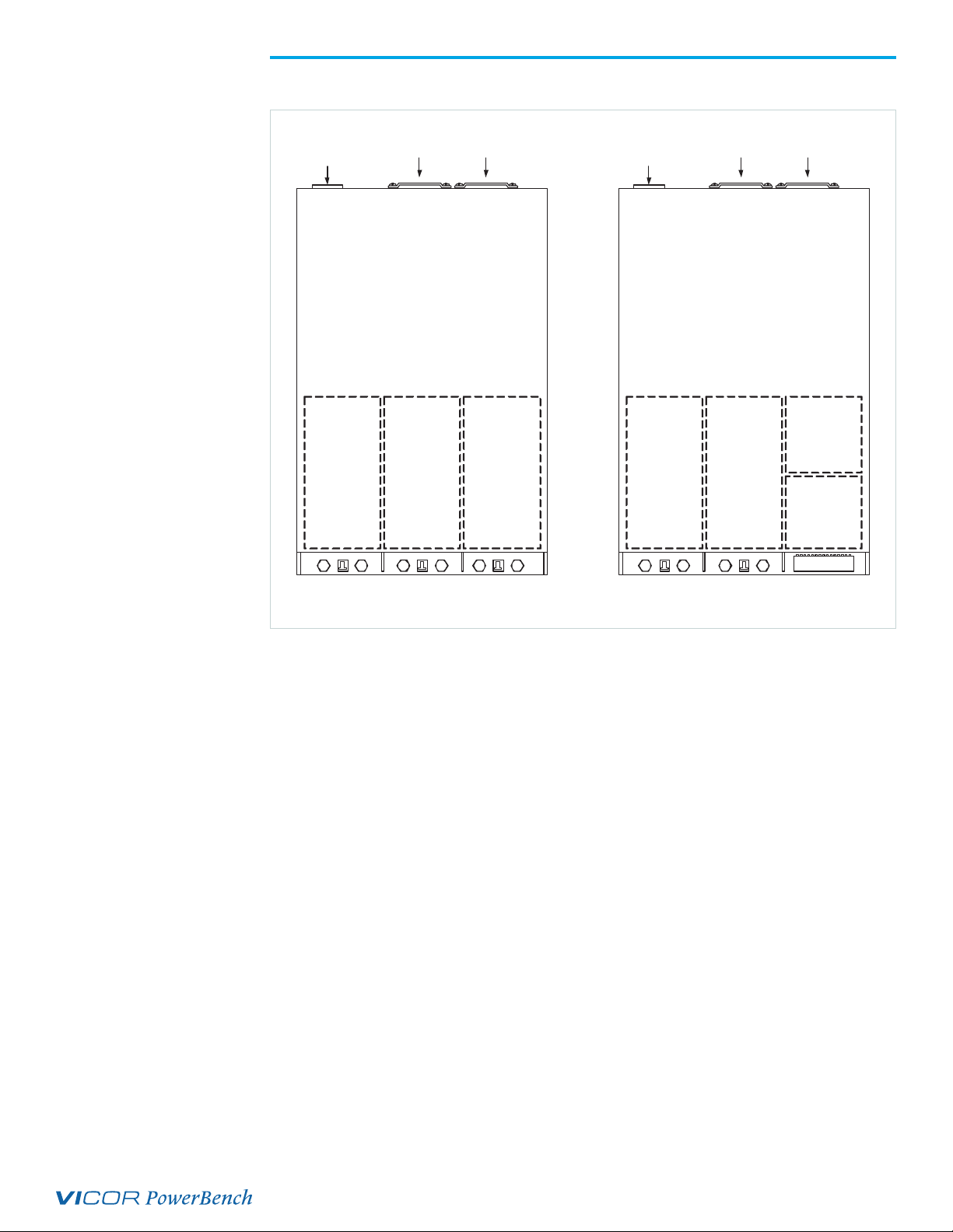
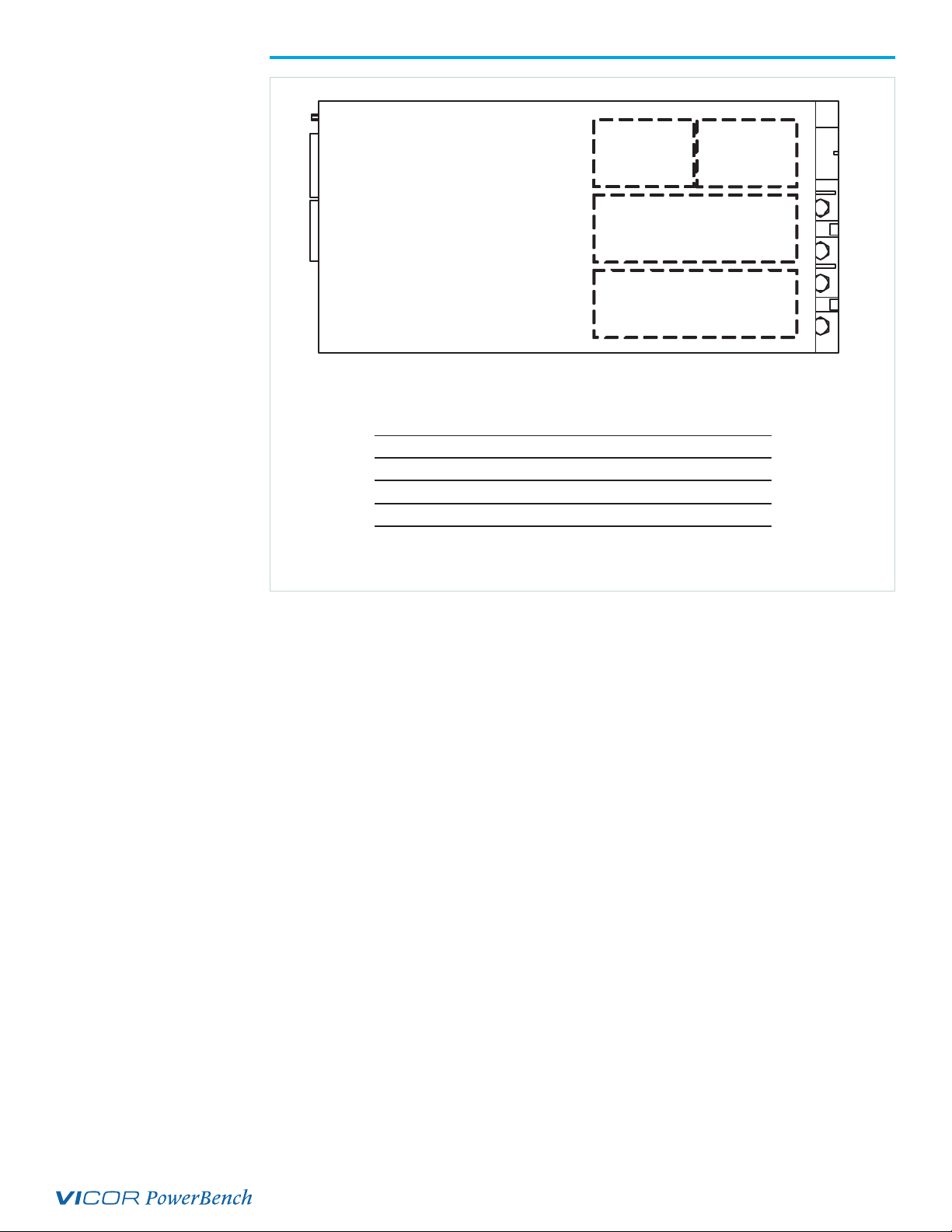
PFC Mini™ Configuration Layout
AC input
Slot 1
Fan
S2-M1S1-M1
Slot 2 Slot 3
Fan
S3-M1
AC input
Slot 1
Fan
S2-M1S1-M1
Slot 2 Slot 3
Fan
S
-
3
S
-
3
M
2
M
1
Shown above are two sample PFC Mini configuration layouts. Due to the configurability nature of
the PFC Mini, various output combinations are possible. See Page 11 for more information about
your output connections. The PFC Mini has three slots, and each slot accommodates either full- or
half-brick modules.
Please note that the maximum output power of the PFC Mini is 1,500W at 230VAC, 800W at 115VAC,
irrespective of the maximum output power of the modules; e.g., if a PFC Mini is configured with
three Maxi modules on the configuration sheet, the maximum output power of the module (600W) is
listed. However, irrespective of the maximum output power of the three Maxi modules (1,800W), the
maximum output power of the PFC Mini is still 1,500W at 230VAC and 800W at 115VAC.
When populated with 12V modules, the maximum output power per slot is 500W (with other modules
it is 600W). Hence, when a 12V Maxi module is used, the maximum output power is limited to 500W. If
a 12V Mini module is used, the maximum output power is limited to 250W.
UG:115 Page 5
Page 6
Output #2
VI-J63-CW-S
E/D#3
V375A5C400BN4
E/D#2
V375A5C400BN4
E/D#1
Configuration Example:
ModulesWATTSAMPSVOLTSSLOT#
ModulesWATTSAMPSVOLTSSLOT#
V375A5C400BN4*800805.01
V375800805.01
V375A5C400BN4*2
V375A5C402
VI-J60-CY-S*50105.03 (M1)
VI-50105.03 (M1)
VI-J63-CW1004.224.03 (M2)
VI-1004.224.03 (M2)
* Actual module part numbers may vary depending on customer configuration
Output #1
VI-J60-CY
E/D#3
-S*
-S
SLOT#3SLOT#2SLOT #1
E/D = Enable/Disable
Part Numbering
PFC Mini™ PMx1-x2 x (x4)-xxxx(-x5)(-x6)
e.g.: PM4-22-2988
PM1-03B-48
PM3-03-2643-2
PM6-60-2888-2-QF
PM = PM
x1 = number of outputs
x2 = number of VI-200™/VI-J00™
x3 = number of Maxi, Mini
x4 = optional - standard product designator
xxxx = configuration/customer specific # assigned by Vicor
x5 = optional factory assigned note MI = rugged chassis + MC for conformal coated rugged
x6 = additional option codes revised to orginal configuration
QF = quiet fan/office enviornment
LL = low leakage
UG:115 Page 6
Page 7
NOTE: SET SCREW MAX
Output Return
TORQUE = 4.4 IN. LBS.
115-230 VAC 10A
47 TO 500 Hz
300VDC
---
L2/N
L1
-
+-
+
9
8
SxJ1 Dual Output connector
DO NOT
OPERATE
WITHOUT
EARTH GND
SxJ2
Locking Key
14
15161718
-S+-
T
T
-S
67
M1 Output
M2 Output
13
+S
+S
45
INPUT CONNECTIONS
MBJ1-1 EARTH GROUND
MSJ1-2 L2-NEUTRAL
MBJ1-3 L1
Output
1112
10
++-
-
+
-
3
12
Pin 1 Identifier
PFC MegaPAC™ Quick Install Instructions
(For mechanical drawing, see Page 9)
Mounting the PFC Mini™
Mount the PFC Mini on either of two sides.
Use #8-32 or 4mm mounting screws. Maximum penetration should not exceed 0.16in [4mm].
Maintain 2in [5,1cm] clearance at both ends of power supply for airflow.
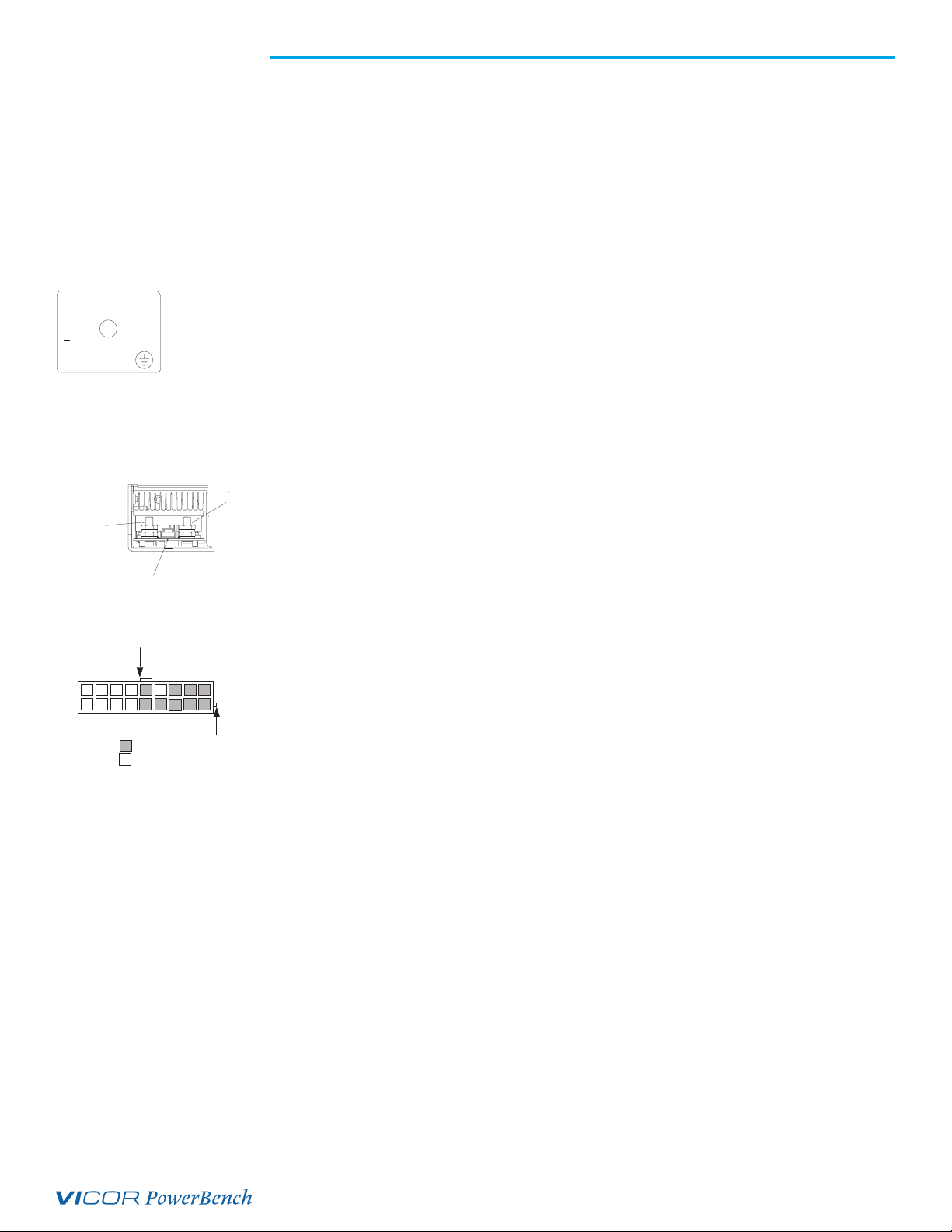
Input Connections
Input Power MBJ1
Apply input AC power to terminal block MBJ1 using a pressure screw terminal.
Strip length of AC power conductors to be 0.35 inches.
Maximum torque is 4.4in.lbs.
Place a fuse or circuit breaker in the input line for safety requirements.
The connector manufacturer recommends the wires not be tinned.
A ferrule can be used to prevent fraying.
Output Connections (see Page 10 for more details on output connectors)
Power Connections
Installing bus bars on output studs (when full-size module is used):
The right stud is Positive and the left stud is the Return.
Remove the top nut and place ring lug over output stud.
Do not remove the lower nut next to the PCB.
Replace and tighten the nut to a torque of 10 inch pounds. Do Not over-tighten nuts.
Installing power connectors with 18-pin molex connectors
SxJ1-1, SxJ1-10, SxJ1-11 are Positive for output #1, while pins
SxJ1-2, SxJ1-3, SxJ1-12 are the Return.
SxJ1-7, S3J1-8 and SxJ1-16 are Positive for output #2, while pins
SxJ1-9, SxJ1-17 and SxJ1-18 are the Return.
[b]
Use Molex mating receptacle #39-01-2180 with #44476-3112 terminals.
Attach 18 – 24AWG stranded wire using Molex tool #11-01-0199.
Current PFC Minis have 18-pin SxJ1 connectors.
Note: Effective January 2001, all PFC Mini units have 18-pin connectors (Molex PN#39-01-2180) vs. the 14-pin
(Molex PN# 39-01-2140). If you already have a 14-pin design in, remove the harness assembly from the 14-pin
connector housing and insert the harness connector pins into the 18-pin connector housing. For further information,
contact an Applications Engineer.
[a]
Outputs with current molex connectors are limited to 9A/pin (27A per output).
[b]
Where x refers to the slot number.
[a]
(when half size module used):
UG:115 Page 7
Page 8
Remove jumpers for
Trim Connector
Remote Sense
Remove jumpers for
Remote Sense on
Output # 2
Connector J2
Remove jumpers for
Remote Sense on
Output # 1
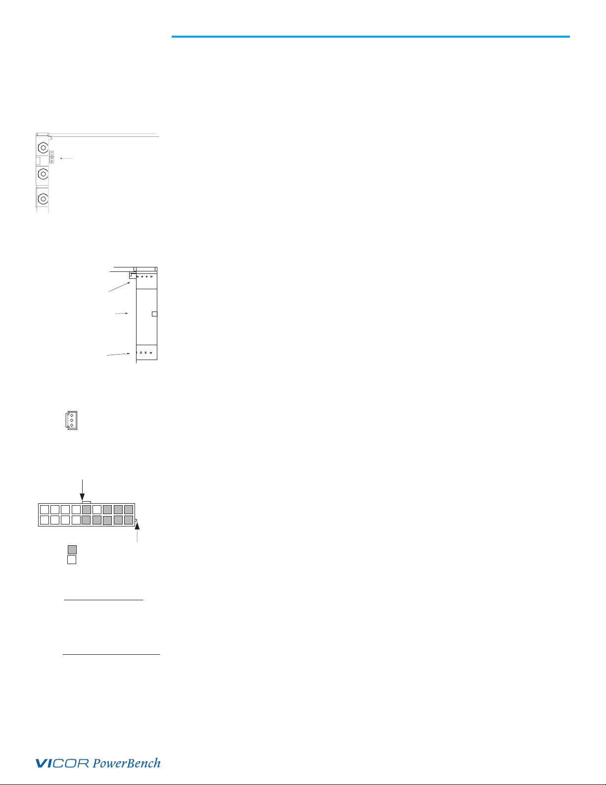
Sense Connections
Note: PFC Mini™ units built after 12/2000 have been equipped with a feature called Autosense. If no sense
connections are made, the PFC Mini will automatically operate in local-sense mode. If remote-sense connections are
made, the PFC Mini will operate in a remote-sense mode.
For units built before 12/2000 (units without Autosense), Sense connections must ALWAYS be made.
Not connecting Sense Lines to their respective outputs can cause failure to the unit.
Sense connections on output connections with studs
PFC Minis are currently shipped with Autosense installed. Those without the Autosense were shipped
with local sense installed. (See note on Page 13)
If remote sense is desired, remove jumpers MBJ1 and J3, located behind the sense connector.
Connector pin SxJ2-2 is the +SENSE and SxJ2-3 is the –SENSE.
Use Molex mating receptacle #50-57-9403 with #16-02-0103 terminals.
Attach terminals to 20 – 22AWG stranded twisted pair wire using Molex tool #11-01-0208.
Attach opposite end of sense lines to point where regulation is desired.
Verify that sense lines are not cross-connected.
Sense connections on output connection with Molex connectors
PFC Minis are currently shipped with Autosense installed. Those without the Autosense were shipped
with local sense installed. (See note on Page 13)
If remote sense is desired, remove jumpers on MBJ1 and J3, located on either side
of the output connector.
Connector pin SxJ1-4 is the +SENSE and SxJ1-5 is the –SENSE for output #1.
SxJ1-13 is the +SENSE and SxJ1-15 is the –SENSE for output #2.
Use Molex mating receptacle #39-01-2180 with #39-00-0039 terminals.
Attach 18 – 24AWG stranded twisted pair wire using Molex tool #11-01-0197.
1
2
3
SxJ2
Locking Key
15161718
-
9
-S+-
+-
T
+
67
8
SxJ1 Dual Output connector
J3 INTERFACE CONNECTION
MATING HDWR:
HOUSING: AMP P/N 205204-4
TERMINALS: AMP P/N 66506-9
SCREW LOCK: AMP P/N 205980-4
CRIMP TOOL: AMP 58448-3
J3 INTERFACE PIN OUT
E/D-1
J3-1
E/D-2
J3-2
E/D-3
J3-3
J3-4
J3-5
J3-6
J3-7
J3-8
J3-9
Pin
Trim Pin Access
+SENSE
–SENSE
14
T
-S
M1 Output
M2 Output
SIGNAL GROUND
VCC +5V 300mA
ACOK AC POWER OK
GSD GENERAL SHUTDOWN
SPARE
SPARE
1112
13
+S
+S
10
++-
-
+
-
3
45
12
Pin 1 Identifier
Trim Connections
Trim connections on outputs with studs:
SxJ2-1 provides trim access.
Use Molex mating receptacle #50-57-9403 with #16-02-0103 terminals.
Attach 20 – 22AWG stranded wire using Molex tool #11-01-0208.
Trim connections on outputs with Molex connectors:
SxJ1-14 provides trim access for output #1, and SxJ1-6 provides trim access for output #2.
Use Molex mating receptacle #39-01-21 with #39-00-0039 terminals.
Attach 18 – 24AWG stranded wire using Molex tool #11-01-0197.
Interface Connections
J3-1 to 3 are Enable/Disable for cards 1-3, respectively.
J3-4 is Signal Ground, J3-5 is +5V, J3-6 is AC Power OK, and J3-7 is General Shutdown.
Use mating receptacle AMP P/N 205204-4 with terminals AMP P/N 66506-9.
Attach terminals to 18 – 24AWG stranded wire.
UG:115 Page 8
Page 9
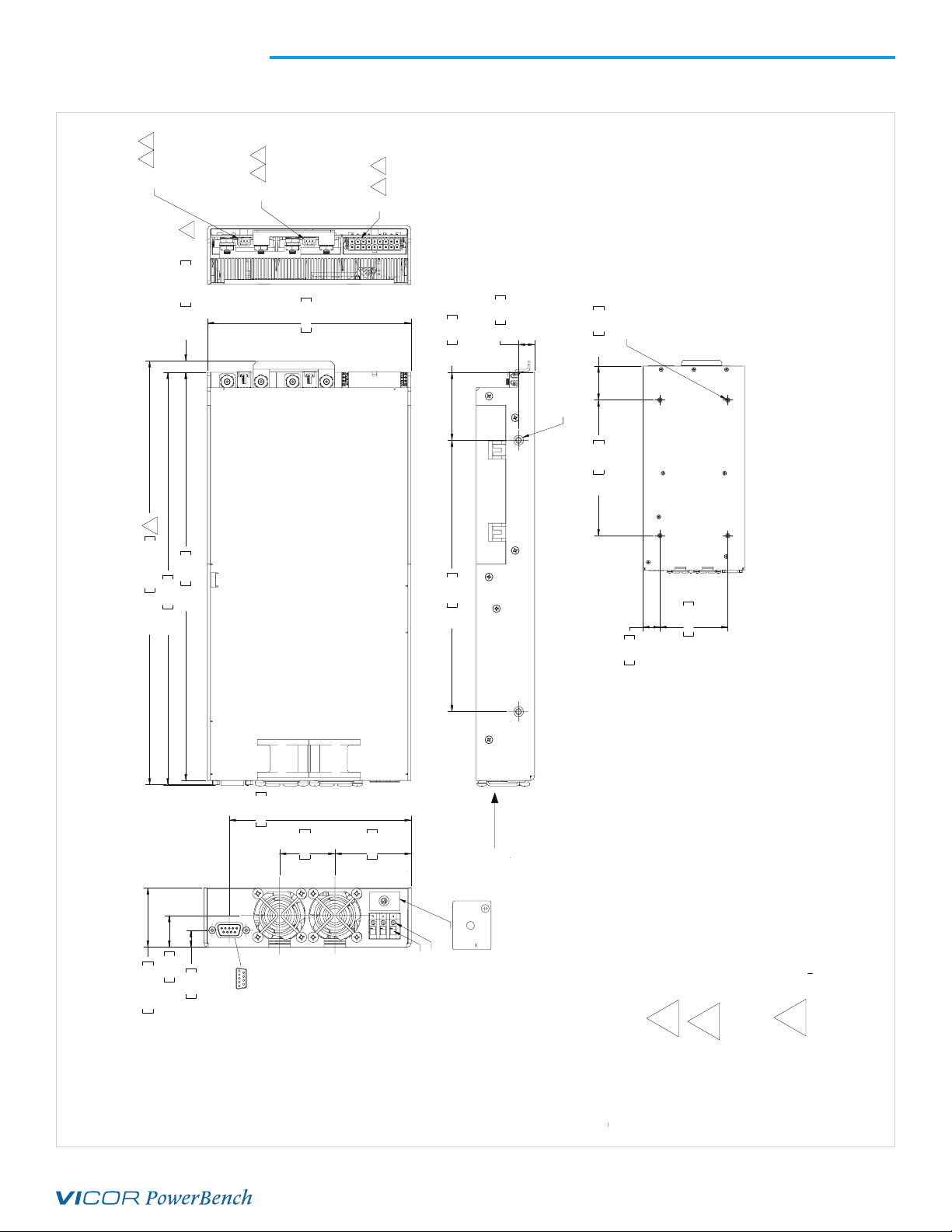
PFC Mini™ Mechanical Drawing
3 4
S3JX
2
SEE PAGE 11 FOR DETAILED OUTPUT
CONNECTION INFORMATION
.34 ±.02 8.64 ±0.51
2
12.03 305.56
12.49 ±.02 317.29 ±0.51
12.16 308.86
4
3
S2JX
6.00 152.40
4
3
S1JX
2.00 50.80
8.00 203.20
.47 11.94
NOTE: FOR INCREASED OUTPUT POWER,
CUSTOMER MOUNTING HOLES:
4X #8-32 X .156 or M4 X 4mm MAX LG.
FROM OUTSIDE OF POWER SUPPLY
CUSTOMER MOUNTING HOLES:
2X #8-32 X .156 or M4 X 4mm MAX LG.
FROM OUTSIDE OF POWER SUPPLY
8.00 203.20 2.00 50.80
CURRENT SHARE BOARDS ARE AVAILABLE.
WITH VI-200/VI-J00 MODULES CSB-01
4.00 101.60
WITH MAXI/MINI MODULES CSB-02
SEE PAGE 21 AND 22 FOR MORE INFORMATION ON
CURRENT SHARE BOARDS.
BOTTOM VIEW
All Westcor power supplies can now be configured online
using VSPOC, the online configurator tool available on vicorpower.com
SCALE: 1:2
1.72 ±.02 43.69 ±0.51
.920 23.37
5 1
.487 12.36
J3 INTERFACE PIN OUT
5.268 133.81
1.600 40.64
9 6
J3-1 E/D-1
J3-2 E/D-2
J3-3 E/D-3
J3-4 SIGNAL GROUND
J3-5 VCC +5V 300mA
J3-6 ACOK AC POWER OK
J3-7 GSD GENERAL SHUTDOWN
J3-8 SPARE
2.210 56.13
DO NOT
WITHOUT
OPERATE
NOTE: SET SCREW MAX
TORQUE = 4.4 IN. LBS.
47 TO 500 Hz
300VDC
115-230 VAC 10A
14 AWG WIRE
CLAMPING SCREWS
J3-9 SPARE
MATING HDWR: (AMP P/N: OR EQUIVALENT)
HOUSING: AMP P/N: 205204-4
TERMINALS: AMP P/N: 66506-9
SCREW LOCK: AMP P/N: 205980-4
J3 INTERFACE CONNECTION
CRIMP TOOL: AMP 58448-3
AIR FLOW
EARTH GND
L2/N
MBJ1-1 EARTH GROUND
MBJ1-2 L2 / NEUTRAL
MBJ1-3 L1
L1
---
MBJ1 INPUT CONNECTIONS
1.00 25.40
NOTES: UNLESS OTHERWISE SPECIFIED
1. INTERPRET DRAWING PER ANSI Y14.5-1994.
WITH OPTIONAL BUSBAR.
A COMPLETE SET OF MATING CONNECTORS CAN
BE PURCHASED FROMWESTCOR BY SPECIFYING
CONNECTOR KIT P/N: 19-130047
REF DESIGNATION LEGEND
MB = MOTHER BOARD
S1 = (SLOT 1) DAUGHTERBOARD MODULES E/D 1.
S2 = (SLOT 2) DAUGHTERBOARD MODULES E/D 2.
S3 = (SLOT 3) DAUGHTERBOARD MODULES E/D 3.
2
3
4
UG:115 Page 9
Page 10

Output Connectors for PFC Mini™
A. OUTPUT STUDS - SINGLE OUTPUT (when populated with full-size modules)
–VOUT
10-32 OUTPUT STUDS
SxJ2 REMOTE SENSE/TRIM
PIN CONNECTOR
+VOUT
3
2
1
–SENSE
+SENSE
TRIM
B. MOLEX CONNECTOR - SINGLE OR DUAL OUTPUT - (when populated with half-size modules)
18-pin Housing
9
18
8
17
7
16
15
6
5
14
13
4
12
3
2
11
10
1
SxJ1 (18-PIN OUTPUT, REMOTE SENSE
AND TRIM PIN CONNECTOR)
PIN DESCRIPTION PIN DESCRIPTION
1 +VOUT M1
2 –VOUT M1
3 –VOUT M1
4 +SENSE M1
5 –SENSE M1
6 TRIM M2
7 +VOUT M2
8 +VOUT M2
9 –VOUT M2
10 +VOUT M1
11 +VOUT M1
12 –VOUT M1
13 + SENSE M2
14 TRIM M1
15 –SENSE M2
16 +VOUT M2
17 –VOUT M2
18 –VOUT M2
MATING CONNECTOR:
HOUSING: MOLEX P/N 50-57-9403
TERMINALS: MOLEX P/N 16-02-0103
USE CRIMP TOOL: MOLEX P/N 11-01-0208
MATING CONNECTOR:
18-PIN HOUSING: MOLEX (39-01-2180)
TERMINAL FEM CRIMP 18 – 24AWG: MOLEX (39-00-0039)
USE CRIMP TOOL: MOLEX (11-01-0197)
The Molex connectors are limited to 9A/pin (27A per output.)
M1 Output
M2 Output
C. MOLEX CONNECTOR - SINGLE OR DUAL OUTPUT SLOT (14-pin Housing - PFC Minis built prior to 1/2001)
14
7
6
13
5
12
4
11
3
10
2
9
1
8
SxJ1 (14-PIN OUTPUT, REMOTE SENSE
AND TRIM PIN CONNECTOR)
PIN DESCRIPTION PIN DESCRIPTION
1 +SENSE M1
2 +OUTPUT M1
3 –OUTPUT M1
4 TRIM M1
5 +OUTPUT M2
6 –OUTPUT M2
7 +SENSE M2
8 –SENSE M1
9 +OUTPUT M1
10 –OUTPUT M1
11 TRIM M2
12 +OUTPUT M2
13 –OUTPUT M2
14 –SENSE M2
MATING CONNECTOR:
14 PIN HOUSING: MOLEX (39-01-2140)
TERMINAL FEM CRIMP 18 – 24AWG: MOLEX (39-00-0039)
USE CRIMP TOOL: MOLEX (11-01-0197)
UG:115 Page 10
Page 11

Figure 2
Input power terminal MBJ1
PFC Mini™ Connector Kit (19-130047) Listing
(Available for purchase)
Item Qty Description Vendor #1 Part #
1 3 HOUSING 3 POS .100 CTR W/LATCH MOLEX 50-57-9403
2 10 TERM FEM CRIMP 22-24AWG SEL GOLD MOLEX 16-02-0103
** CRIMP TOOL FOR ITEM 2 MOLEX 11-01-0208
3 1 HOUSING FEMALE D-SUB 09 PIN AMP 205204-4
3 10 TERM MALE CRIMP 22 – 24 AWG TIN AMP 66506-9
3 1 SCREW LOCK MALE (1 PAIR) AMP 205980-4
** CRIMP TOOL FOR ITEM 3 AMP 58448-3
4 3 HOUSING 18 POS .165 CTR W/LATCH MOLEX 39-01-2180
5 60 TERM FEM CRIMP 18 – 24AWG SEL GOLD MOLEX 39-00-0039
** CRIMP TOOL FOR ITEM 5 MOLEX 11-01-0197
6 60 TERM FEM CRIMP 16AWG SEL GOLD MOLEX 45750-3211
** CRIMP TOOL FOR ITEM 6 MOLEX 11-01-0199
** ITEMS FOR REFERENCE ONLY (NOT INCLUDED IN KIT)
Interface Connections
Chassis Input Power Terminals (MBJ1)
Input AC power is applied to terminal block MBJ1 using a pressure screw terminal that accepts a
maximum wire size of 14AWG. The insulation should be stripped 0.35 inches and the maximum torque
applied to the screws should not exceed 4.4in.lbs. The connector manufacturer recommends the wires
not be tinned. A ferrule (Phoenix P/N 32-00-58-0, provided in optional connector kit) can be used to
prevent fraying. MBJ1-1 (GND) is Earth Ground for safety; MBJ1-2 (L2) and MBJ1-3 (L1) are the other
"hot" connections.
A fault clearing device, such as a fuse or circuit breaker, with a maximum 15A rating at the power supply
input is required for safety agency compliance. It should be sized to handle the start up inrush current of
8.5APK at 115 VAC an d 17APK at 230VAC.
NOTE: SET SCREW MAX
TORQUE = 4.4 IN. LBS.
115-230 VAC 10A
47 TO 500 Hz
300VDC
---
L2/N
L1
DO NOT
OPERATE
WITHOUT
EARTH GND
INPUT CONNECTIONS
MBJ1-1 EARTH GROUND
MSJ1-2 L2-NEUTRAL
MBJ1-3 L1
Output Power Connections
There are two types of output power terminals available in the PFC Mini. Outputs from full-sized
converters are terminated in two 10-32 plated steel bolts. The positive polarity of the output is the
right bolt when viewed from the output end. Outputs from half-sized converters terminate in a
Molex connector.
Note: The Molex connectors are limited to 9A/pin (27A/output). Each power output is isolated, so outputs of positive
or negative polarity can be configured through proper selection of the output reference terminal.
UG:115 Page 11
Page 12

Figure 3
18 Pin DUAL MINI AND JR. MODULE OUTPUT CONNECTIONS
14 PIN DUAL MODULE OUTPUT CONNECTIONS
Power connections for
single output
In order to minimize parasitic-cable inductance and reduce EMI, the output power cables should be
routed in close proximity to one another and large current loops should be avoided. To avoid excessive
voltage drop, do not undersize power cables, especially for high-current outputs. Excessive cable
inductance coupled with large-capacitive loading can introduce instability in switching power supplies.
This problem can be avoided with proper system design. Consult the Vicor Applications Engineering
Department for assistance with applications that use long cable lengths and excessive load capacitance.
Note: Effective January 2001, PFC Minis using VI-J00 modules on a dualboard (dual output) now require an 18-pin
connector (Molex PN# 39-01-2180) vs. a 14-pin (Molex PN# 39-01-2140), making them the same as dualboards
with Mini converters. If you already have a 14-pin design in, the change to the 18-pin should not affect your design
in. Remove the harness assembly from the 14-pin connector housing and insert the harness connector pins into the
18-pin connector housing. Contact Field Applications for further information.
Output
Output Return
SxJ2
Figure 4
Power connections for
dual output
1213
6
5
PIN DESCRIPTION
SxJ1-1 +SENSE M1
SxJ1-2. +OUTPUT M1
SxJ1-3. –OUTPUT M1
SxJ1-4. TRIM M1
SxJ1-5. +OUTPUT M2
SxJ1-6. –OUTPUT M2
SxJ1-7. +SENSE M2
1011
814
9
234
17
PIN DESCRIPTION
SxJ1-8. –SENSE M1
SxJ1-9. +OUTPUT M1
SxJ1-10. –OUTPUT M1
SxJ1-11. TRIM M2
SxJ1-12. +OUTPUT M2
SxJ1-13. –OUTPUT M2
SxJ1-14. –SENSE M2
16
18
17
9
PIN DESCRIPTION
SxJ1-1.
+OUTPUT M1 +OUTPUT M1
SxJ1-2.
–OUTPUT M1
SxJ1-3.
–OUTPUT M1 –OUTPUT M1
SxJ1-4.
+SENSE M1 +SENSE M2
SxJ1-5.
–SENSE M1
TRIM M2
SxJ1-7. SxJ1-16.
+OUTPUT M2
SxJ1-8. SxJ1-17.
SxJ1-9. SxJ1-18.
131415
45678
PIN DESCRIPTION
SxJ1-10.
SxJ1-11.
SxJ1-12.
SxJ1-13.
SxJ1-14.
SxJ1-15.SxJ1-6.
11
10
12
1
23
+OUTPUT M1
TRIM M1
–SENSE M2
+OUTPUT M2+OUTPUT M2
–OUTPUT M2
–OUTPUT M2–OUTPUT M2
UG:115 Page 12
Page 13

Figure 5
r
output connector for
Removing local-sense jumpers
+SENSE/ –SENSE (SxJ2/SxJ1)
Current PFC Mini™ units are shipped with Autosense installed. If the unit does not have Autosense,
sense selection is very important. In units without Autosense, the sense lines for the outputs are
shipped from the factory with local sense installed. If remote sense is desired the local-sense jumpers
can be removed for individual outputs. If the local-sense jumpers are removed, the sense lines must be
connected for remote sense. Leaving the sense lines open will prevent proper output regulation
and can result in damage to the unit.
When local sense is used, the power supply will regulate the output at the output terminals. The voltage
appearing at the load may drop slightly due to voltage drop in the power cables. If it is necessary
to compensate for voltage drop along the output power cables, the output can be trimmed up or
configured for remote sense. Use stranded twisted pair 20 – 22AWG wire for the remote-sense lines.
Remote sense can compensate for a voltage drop of up to 0.5V, or 0.25V on each leg.
Installing remote sense requires the local-sense jumpers to be removed. On single output cards, the
local-sense jumpers are located behind the sense connector on MBJ1 and J3. To remove the jumpers,
make certain the power to the supply is off and pull them off the connectors MBJ1 and J3. On dual
output cards, the local-sense jumpers are on either side of the output connector at MBJ1 and J3. The
jumpers at MBJ1 are for output #1 and the jumpers at J3 are for output #2.
The sense connector for a single output board is a 3-pin connector providing the +SENSE connection on
SxJ2-2 and the –SENSE connection on SxJ2-3. The sense connector for a dual output board is an 18-pin
connector that also provides the output and trim connections. +SENSE and –SENSE for the first output
are located on SxJ1-4 and SxJ1-5, respectively. +SENSE and –SENSE for the second output are located on
Sx J1-13 and SxJ1-15, respecti vely.
TOP VIEW
Local Sense
jumpers are to
the left of the output
connector for
.
Output # 2
Single Output Sense Connections
Local Sense jumpers
located behind
the Sense Connector.
14 Pin Dual Output Sense Connectors
Local Sense
jumpers are to
the left of the
1011
814
1213
9
6
234
17
5
Output # 1
Single Output Sense Connections
Local Sense jumpers
located behind
the Sense Connector.
END VIEW
Dual Output Sense Connections
Remove jumpers for
Remote Sense on
Output # 2
18 Pin Dual Output Connectors
Local Sense
jumpers are to
the left of the
output connector
for Output # 2
Connector SxJ1
18
1314151617
9
Remove jumpers fo
Remote Sense on
Output # 1
11
10
12
45678
1
23
Local Sense
jumpers are to
the left of the
output connector
for Output # 1
UG:115 Page 13
Page 14

Figure 6
Remote sense
Figure 7
External trim
To Error
Amplifier
+OUT
+SENSE
Load
–SENSE
–OUT
Use 20 – 22AWG Twisted Pair Wires
Use 20 – 22AWG
+P +OUT
Twisted Pair Wires
(Remote Sense)
R1
SxJ2-2 +SENSE
R2
SxJ2-1
+
R
R5
TH
V
1
V
–
REF
R3
R4
R6
SxJ2-3 –SENSE
–P –OUT
R8
R7
+
V
2
–
Load
Table 1
Module internal
reference voltages and
Thevenin resistances
Use 20 – 22AWG Twisted Pair Wires
Output Module V
REF
R
TH
VI-200™/VI-J00™ ≥3.3V 2.5V 10.0kΩ
VI-200/VI-J00 <3.3V 0.97V 3.88kΩ
Maxi, Mini Micro series (Predefined) 1.23V 1kΩ
Maxi, Mini Micro series (User Defined) 1.23V Consult Factory
External Trim (SxJ2/SxJ1)
The Trim pin at SxJ2 is referenced to the –SENSE pin and can be used for external control of the output
voltage. For dual-output cards, the trim pins are available at SxJ1-14 and SxJ1-6 for outputs 1 and 2,
respectively. A 10% increase to the trim pin voltage will result in a 10% increase in output voltage.
Reducing the trim-pin voltage by 10% will result in a 10% decrease in output voltage.
Note: Converters are sometimes pre-trimmed at the factory if a non-standard output voltage is requested. If
a non-standard voltage is requested, the resistor calculations will differ from those that follow. Consult Vicor
Applications Engineering for assistance.
UG:115 Page 14
Page 15

Example:
±10% Trim adjust on a 12V nominal output.
Figure 7 shows a typical variable trim circuit. Using a 10kΩ trimpot (R7),
the resistor values for R6 and R8 can be calculated as follows:
V1 = V
IR5 = (2.75V – V
+ 10% = 2.75V Given: V
REF
)/RTH = (2.75V – 2.5V)/10kΩ = 25µA Given: RTH = 10kΩ (see Table 1)
REF
= 2.5V (see Table 1)
REF
Setting the bottom limit:
VR6 = 2.5V – 10% = 2.25V
And since IR5 = IR6 = 25µA,
R6 = VR6/IR6 = 2.25V/25µA = 90kΩ
V2 = V1 + VR6 = 2.75V + 2.25V = 5V
IR7 = V2/R7 = 5V/10kΩ = 500µA
IR8 = IR7 + IR6 = 525µA
VR8 = (V
+ 10%) – V2 = 13.2 – 5V = 8.2V Given: V
NOM
NOM
= 12V
R8 = VR8/IR8 = 8.2V/525µA = 15.62kΩ
CONSULT APPLICATIONS ENGINEERING WHEN TRIMMING OUTPUTS BELOW 5V.
Signal Ground (J3-4)
Signal Ground on J3-4 is an isolated secondary ground reference for all J3 interfacing signals. This is not
the same as Earth Ground on input power connector MBJ1.
Figure 8
Enable / disable and
general shut down
Enable/Disable (J3-1 to J3-3)
The Enable/Disable control pins allow outputs to be sequenced either on or off. J3-1 through J3-3 are
the control pins for output cards 1 through 3, respectively. For 2-output cards, both outputs are enabled
or disabled with a single control. The Enable/Disable pins should be pulled low to less than 0.7V with
respect to Signal Ground to disable the outputs. They will source 4mA maximum. These pins should be
open circuited or allowed to exceed 4.5V when enabled. Do not apply more than 5V to these inputs.
A TTL "1" applied to the base of the transistor turns
output OFF. Pin 1 (or Pin 7 for GSD) is pulled Low
with respect to Signal Ground.
Enable/Disable Output 1
Enable/Disable Control
General Shutdown
Signal Ground
TTL "1" (OFF)
TTL "0" (ON)
1
0
J3
5
1
7
4
PFC Mini
Vcc
UG:115 Page 15
Page 16

Figure 9
Enable / disable control of
Maxi, Mini, Micro series
module arrays
Enable / Disable Control of Maxi, Mini, Micro Series Module Arrays
When using the enable / disable function on an output that consists of two or more Maxi/Mini series
modules, it is necessary to connect the enable / disable pins of the corresponding module locations
together such that both modules are commanded to turn ON or OFF simultaneously.
Example: S1 and S2 has been configured as a single output parallel array (see Figure 9)
In order to disable the 48V output, enable / disable 1 and 2 should be shorted together as shown
in Figure 9. With enable / disable 1 and 2 connected together, a single switch can then be used to
remotely enable and disable the output.
Note: For single-output Maxi/Mini series power supply configurations, the simplest method of remotely enabling and
disabling the output is to use the General Shut Down (GSD) function.
J3
1
2
3
4
5
6
7
8
9
V375A5C400A
S3
V375A48C600A
S2
1
2
3
1
2
3
J1
V373A48C600A
S1
1
2
3
Load
General Shutdown/GSD (J3-7)
The GSD control pin on J3-7 allows simultaneous shut down of all outputs. This pin must be pulled
down to less than 0.7V and will source 4mA maximum to shut down all outputs. The GSD pin should be
open circuited or allowed to exceed 4.5V when not in use or when the outputs are to be enabled. Do
not apply more than 5V to this input at any time. Normal open-circuit voltage is 1.5 – 3V with respect
to signal ground.
AC OK (J3-6)
AC OK is an active high TTL-compatible signal and provides a status indication of the AC input power.
It is on pin J3-6 and is capable of sinking 16mA maximum. This signal switches to a TTL "1" when the
high-voltage bus exceeds low-line condition during turn on. Upon loss of input power, the bus voltage
will drop, causing the AC OK signal to go low. A minimum of 3ms hold-up time is provided for a
1,200W load following the loss of the AC OK signal.
UG:115 Page 16
Page 17

Figure 10
AC OK
J3
+5V
Figure 11
Auxiliary V
2.49kΩ
PN2222
Pin 6
AC Power OK
Pin 4
Signal Ground
Bus
Monitor
10kΩ
Auxiliary VCC +5V/0.3A (J3-5)
The VCC on J3-5 is an auxiliary 5V regulated power source. It is +5VDC ±5% with respect to signal
ground and can supply 300mA maximum. It is short-circuit proof, but if shorted all outputs will shut
down through the enable / disable circuitry.
CC
+5V/300mA
78M05
J3
J3-5
Auxiliary Vcc
0.1µF
Signal Ground
J3-4
Single-Output Power Supplies (Arrays)
The Vicor standard configuration for single-output power supplies is to set the left module (as seen
from looking at the power supply output) as the controlling module of the array.
UG:115 Page 17
Page 18

PFC Mini - without change
PFC Mini - with change
Minor Changes for PFC Mini™ Shipped October 2005 Onwards
As part of our philosophy of continuous improvement for the PFC Mini, Vicor made a number of
changes to the unit. Usually such actions have no impact on form, fit, or function of the supplies. In
this instance, the improvements required minor changes in the external appearance of the supply. The
fans have been moved 0.62in and are now centered. The D-Sub logic connector has also been rotated
90 degrees. Please see the following photos for a visual comparison. No other external dimensions,
mounting locations, or performance characteristics have been changed.
133.81
5.268
40.64
1.600
.920
±0.51
23.37
1.72 ±.02 43.69
.487 12.36
How to Identify When Your Unit was Manufactured
Serial numbers for Vicor products are determined as follows:
XXXXXXXMMYY
XXXXXXX = Factory assigned
MM = Month of manufacture
Y = Last digit of year of manufacture
2.210
56.13
UG:115 Page 18
Page 19

Figure 12
PFC Mini™ output power vs.
AC input voltage
PFC Mini™ Output Power vs. Input Voltage
PFC Mini Output Power vs. AC Input Voltage
1600
1400
1200
1000
800
85
638W
145125105
165
Input Voltage (VAC)
600
400
Output Power (Watts)
200
0
200V
AC
245225205185
265
Figure 13
PFC Mini output power vs.
DC input voltage
PFC Mini Output Power vs. DC Input Voltage
1600
1400
1200
1000
800
600
400
Output Power (Watts)
200
0
100
750W
140180 220260 300340 380
Input Voltage (VDC)
UG:115 Page 19
Page 20

Specifications
General
Number of Outputs 1 – 6
Efficiency >80%
cURus – UL 60950-1, CSA 60950-1;
Safety Approvals
Maximum Output Power+
(+Not to exceed an input current of 10A)
Note: Only PFC Minis™ populated with 12V Maxi modules are limited to 500W max. per slot.
With 12V Mini modules, it is limited to 250W.
Input 85 – 264VAC, 47 – 500Hz; 100 – 380V
Line/Load Regulation
Line Regulation Maxi/Mini: ±0.20% max to 0.3% max LL to HL, Full Load
Inrush Current 8.5APK at 115VAC; 17APK at 230V
Ride Through Time 20ms at 1,200W load
Conducted EMI
Power Factor 0.99 at 115VAC; 0.95 at 230V
Voltage Fluctuations and Flicker EN61000-3-3
ESD Susceptibility EN61000-4-2, Level 3, Performance Criteria A
RF Radiated Immunity, 10v/m EN61000-4-3, Performance Criteria A
Transient Burst Immunity EN 61000-4-4, Level 3, Performance Criteria B
Surge Immunity EN 61000-4-5 Installation Class 3, Performance Criteria B
RF Conducted Immunity EN61000-4-6, Limit Class 3 Performance Criteria A
Voltage Dips and Interrupts EN61000-4-11
Dielectric Withstand
MI Chassis Overvoltage and Transients Compliant to Mil-STD 704 and 1399
Note: See Vicor module specifications. A preload may be necessary for modules trimmed down below 90% of
normal output voltage.
cTÜVus – EN 60950-1, UL 60950-1, CSA 60950-1
CE Mark – Low Voltage Directive, 73/23/EEC amended by 93/68/EEC
Note: certain MI chassis may not carry all safety approvals
>800W at 115VAC;
1,500W at 230V
AC
Input
DC
VI-200™/VI-J00™: ±0.2% max, 10% to full load;
±0.5% max, 0 – 10% load
AC
VI-200/VI-J00 Ss:
EN55022 Class B
Maxi, Mini
(some configurations may meet Class B):
EN55022 Class A
Mil-STD 461 will require external filter
AC
Primary to Chassis GND = 2,121V
Primary to Secondary = 4,242V
Secondary to Chassis GND = 750V
DC
DC
DC
UG:115 Page 20
Page 21

Specifications (Cont.)
Environmental
Storage Temperature –40 to +85°C
Operating Temperature
Full Power
Half Power
–20 to +45°C
–20 to +65°C (–40 to +65°C optional with MI chass)
Specific temperature data on all module configurations can be obtained by contacting
Applications Engineering.
Mil-STD 810
Shock and Vibration
(MI Chassis) Altitude
Derate 2.6% total output power for each 1,000ft to a maximum
operating altitude of 15,000ft. Non-operating storage maximum
altitude is 40K. 75% maximum load
Humidity 0 – 95% non condensing
Product Weight 5.5lbs (2,5kg)
Dimensions 1.72 x 6.0 x 12.2in [43,6 x 152,4 x 309,9mm]
Warranty
[d]
2 years limited warranty.
See vicorpower.com for complete warranty statement.
VI-200™/VI -J00™ Modules
Parameter Min Typ Max Units Notes
Set-Point Accuracy
[e]
0.5 1
Load/Line Regulation
Load/Line Regulation
Temperature Regulation 0.01 0.02 %/°C Over rated temperature
[c]
(–40 to +45°C optional with MI chassis)
Output
%
±0.2
±0.5
of V
%
10% to full load
%
No load to 10% load
NOM
Long-Term Drift
Output Ripple & Noise:
≤10V
>10V
OUT
OUT
100
1.0
Voltage Trim Range
VI-200/VI-J00 series slots 50 – 110
Total Remote Sense
Compensation
OVP Set Point
[f]
0.5 Volts
115 125 135
Current Limit 105 115 125
Short Circuit Current 20 (105
[g]
) 130 %
mV
20MHz bandwidth
%
20MHz bandwidth
V
OUT
%
±10% on 10 – 15V
V
OUT
Autosense.
See Pages 8 & 14
%
Recycle Power
V
OUT
% of
Auto Recovery
I
MAX
OUT
Overtemperature Limiting Not available on VI-J00
[c]
45°C is the maximum operating temperature. If one is using a Maxi/Mini module less than 24V output and more
than 500W, the maximum operating temperature is 40°C.
[d]
Opening, repairing or modifying the unit will void the warranty. If you have any problem with the power supply,
please contact Customer Service at 1-800-735-6200. If the unit needs to be returned for inspection/analysis,
an RMA number will be issued. All units must have a RMA number prior to return.
[e]
For special, adjustable voltages and 48VDC outputs, maximum setpoint accuracy is 2% of V
Note: See individual module data sheets for specific module specifications.
[f]
131% Nominal for Booster Modules. No OVP for VI-J00
[g]
VI-J00 modules only
NOM
.
UG:115 Page 21
Page 22

Specifications (Cont.)
Maxi, Mini, Micro Series Modules (Maxi and Mini Modules Only)
Parameter Min Ty p Max Units Notes
Set-Point Accuracy
Load Regulation
Temperature Regulation 0.002 0.005 %/°C –20 to 100°C
Long-Term Drift
Output Ripple & Noise:
≤10V
OUT
>10V
OUT
Voltage Trim Range
Maxi/Mini Slots 10 – 110 % V
Total Remote-Sense
Compensation
OVP Set Point 112 135 % V
Current Limit 115 135 % of I
Overtemperature Limiting 100 115 MMM OTL is non-latching
[c]
45°C is the maximum operating temperature. If one is using a Maxi/Mini module less than 24V output and more
than 500W, the maximum operating temperature is 40°C.
[d]
Opening, repairing or modifying the unit will void the warranty. If you have any problem with the power supply,
please contact Customer Service at 1-800-735-6200. If the unit needs to be returned for inspection/analysis,
an RMA number will be issued. All units must have a RMA number prior to return.
[e]
For special, adjustable voltages and 48VDC outputs, maximum setpoint accuracy is 2% of V
Note: See individual module data sheets for specific module specifications.
[f]
131% Nominal for Booster Modules. No OVP for VI-J00
[g]
VI-J00 modules only
[e]
±0.5
±0.1
100
1.0
±1 % of V
% of V
mV
% V
0.5 Volts
See module design guide
NOM
for exact specifications
NOM
20MHz bandwidth
20MHz bandwidth
OUT
Preload may be required
OUT
Autosense.
See Pages 8 & 14
Recycle Power
OUT
Auto Recovery
MAX
NOM
.
UG:115 Page 22
Page 23

Current Share Boards – Optional Feature
"Current Sharing" also known as load sharing, is the ability to divide the output current evenly across
all active power supplies. This greatly reduces stresses on each power supply and allows them to run
cooler, resulting in higher reliability. Standard "Current Sharing" techniques typically utilize shunt
resistors or Hall-Effect devices to measure the current from each power supply. Power-shunt resistors
continually dissipate power and require cooling especially when dealing with high output currents of
>100A. Hall-Effect devices measure magnetic fields generated by current flowing through a conductor
and, although they dissipate no power, they tend to be large and expensive.
First developed by Vicor engineering for paralleling MegaPAC™ supplies, the box-to-box current share
board or CSB allows two or more Vicor power supplies to current share by utilizing the inherent voltage
drop produced in the negative output return cable. This eliminates the need for additional shunt
resistors or expensive Hall-Effect devices and provides a simple 5-wire connection method to achieve
a ±1mV accuracy between the negative output power rails. This accuracy translates to a 1% current
sharing if there is a total of 100mV conductional voltage drop in the negative return path.
Constructed as a current source to drive the trim pin of a Vicor module, the design uses an accurate
comparator circuit to monitor the power returns. In addition, the circuit is unidirectional and can only
trim an output voltage up. The benefit is that only the supply that is supporting less current is adjusted
up. This action balances the currents to the load by matching the output voltages of the supplies. In
the case of one supply failing, the circuit will attempt to trim the failed supply only. This will leave the
remaining functional supply alone to provide power to the load at its nominal voltage. Thus the circuit
also offers simple redundancy. In addition, because CSB functions as a current source, the trim outputs
(T1 and T2) of the CSB can be placed in parallel to create a summing node. This allows current sharing
between more than two supplies by paralleling the T2 output of one CSB circuit with the T1 output
of the next CSB.
Please note: The CSB is not intended for use in Hot-Swap applications.
Figure 14
CSB interconnect example
Power Supply 1
24V@1kW
Power Supply 2
24V@1kW
+OUT
+S
TRIM
–S
–OUT
+OUT
+S
TRIM
–S
–OUT
Yellow
Brown
White
Black
D*
D*
T1
–V1
T2
–V2
C SB02
Power
+VOUT
Red
–VOUT
UG:115 Page 23
Page 24

Current Share Boards – Optional Feature (Cont.)
Requirements:
1. For proper operation, the power supplies being paralleled should be enabled at the same time.
2. –OUT conductors must be of equal length and wire gauge. Separate –OUT conductors must be
used from each supply to the load, or the use of a "Y" connection to a common point must be
used as shown in Figure 1. Each leg of the "Y" must have a minimum of a few millivolts of drop in
order for proper operation. 50 – 100mV of drop will provide from 5 to 1% accuracy.
3. –V1 and –V2 for all box-to-box circuits must be connected directly at the negative output power
studs or terminals to achieve accurate current sharing.
4. D* can be added if redundancy is needed. If redundancy is not required, D* can be replaced with
direct wire connections.
5. When using D*, the Power input should be connected on the cathode side of the paralleling diodes
as shown in Figure 14.
6. Terminate Sense Leads either locally or remotely as shown in Figure 1.
7. For paralleling more than two supplies consult Applications Engineering for assistance.
UG:115 Page 24
Page 25

Current Share Boards – Optional Feature (Cont.)
J1 Pinout
Pin Description
1 Power
2
T1
3 –V1
4
T2
5 –V2
6 No Connection
1.74"
[44.2mm]
1.500"
[38.1mm]
0.12"
[3.0mm]
0.12"
[3.0mm]
0.900"
[22.9mm]
[29.0mm]
Figure 15. Mechanical Drawing
1.14"
0.13" [3.3mm] Dia Non
Plated thru hole 4
places
12
34
56
Molex CT43045F surface mountable
connector. .390" height above board.
24.0" +/– 1.0"
P1
Red, 22 AWG
Yellow, 22 AWG
Brown, 22 AWG
White, 22 AWG
Black, 22 AWG
P ower
T1
–V1
T2
–V2
Figure 16. Cable Drawing
Specifications:
1. Power: 2 – 50VDC at 5mA maximum.
2. Accuracy: ±1mV between –V
connections.
OUT
3. Output current when not trimming up: ±1µA (VI-200/J00), ±5µA (Maxi, Mini, Micro series).
4. Use four non-plated through holes with standoffs for mounting.
5. CSB01 MUST be used for current sharing VI-200™/VI-J00™ series converters (VI-200/J00).
6. CSB02 MUST be used for current sharing Maxi, Mini, Micro series converters
(Maxi, Mini and Micros).
PLEASE NOTE: THE CSB IS NOT INTENDED FOR HOT-SWAP APPLICATIONS.
UG:115 Page 25
Page 26

Low-Leakage Version
(Available upon request)
If low leakage is required, Vicor has a PFC Mini™ model variant (must be requested). This model
enables the user to meet various additional specifications. The advantage of the low-leakage PFC
Mini power supply is in multiple power supply systems that have one AC input. This option will lower
the input leakage current for these products to 500μA or less (may vary if Maxi, Mini, Micro series
modules are used. Contact Applications Engineering for more details.) An additional external EMI filter is
typically required.
How Low-Leakage is Obtained
Low leakage is obtained with the removal of the "Y" capacitors from within the EMI filter of the
PFC Mini. This reduces the leakage current from the AC input to AC ground (chassis) to below 500μA.
At the same time, since the "Y" capacitors are a vital component of the EMI filter, without them, the
EMI will go up. When this happens, the unit may no longer meet Vicor published specifications for
conducted EMI. In order to reduce the EMI to within an acceptable limit, an additional external EMI filter
may be required. All safety agency certifications for the PFC Mini remains intact.
[h]
Contact Applications
Engineering for more information.
[h]
Please note that the PFC Mini (including low leakage version) is NOT UL2601 compliant.
Low Output Ripple
If output ripple of 10mV
or 0.15% (whichever is greater) is required, a PFC Mini with RAM™
P-P
modules can be configured if the maximum output power per output does not exceed 100W. If this
configuration is required, please contact: apps@vicorpower.com to have it configured.
If there are space restrictions, an external RAM™/µRAM™ can also be used.
Office Environment Fan
A PFC Mini using an office environment fan is available. Please note that the maximum output power
for this version is 1,200W. The maximum output power per slot is limited to 500W.
Molex Connector Limitation
Please note that those PFC Mini configurations that use Molex connectors are limited to 9A/pin
(27A per output). This is a Molex connector limitation, NOT a module power limitation.
UG:115 Page 26
Page 27

For more information about this or other Vicor products, or for assistance with component-based
power system design, contact the Vicor office nearest you. Vicor comprehensive line of power
solutions includes modular, high-density DC-DC converters and accessory components, configurable
power supplies, and custom power systems. Vicor designs and builds configurable power supplies
incorporating Vicor high-density DC-DC converters and accessory components.
This product line includes:
LoPAC™ FAMILY:
PFC MicroS™
PFC Micro™
PFC Mini™
MegaPAC™ FAMILY:
PFC MegaPAC™
4kW MegaPAC™
4kW MegaPAC-EL™ (Low Noise)
PFC MegaPAC™ (High Power)
PFC MegaPAC™ (Low Noise/High Power)
PFC MegaPAC-EL™
Autoranging MegaPAC™
Mini MegaPAC™
ConverterPACs™
Others:
FlatPAC-EN™
PFC FrontEnd™
MicroPAC™
Conduction Cooled MicroPAC™
Rugged COTS versions (MI) are available for the PFC Micro, PFC MicroS, PFC Mini, PFC MegaPAC,
Standard MicroPAC and Conduction Cooled MicroPAC.
UG:115 Page 27
Page 28

Limitation of Warranties
Information in this document is believed to be accurate and reliable. HOWEVER, THIS INFORMATION
IS PROVIDED “AS IS” AND WITHOUT ANY WARRANTIES, EXPRESSED OR IMPLIED, AS TO THE
ACCURACY OR COMPLETENESS OF SUCH INFORMATION. VICOR SHALL HAVE NO LIABILITY FOR THE
CONSEQUENCES OF USE OF SUCH INFORMATION. IN NO EVENT SHALL VICOR BE LIABLE FOR ANY
INDIRECT, INCIDENTAL, PUNITIVE, SPECIAL OR CONSEQUENTIAL DAMAGES (INCLUDING, WITHOUT
LIMITATION, LOST PROFITS OR SAVINGS, BUSINESS INTERRUPTION, COSTS RELATED TO THE REMOVAL
OR REPLACEMENT OF ANY PRODUCTS OR REWORK CHARGES).
Vicor reserves the right to make changes to information published in this document, at any time
and without notice. You should verify that this document and information is current. This document
supersedes and replaces all prior versions of this publication.
All guidance and content herein are for illustrative purposes only. Vicor makes no representation or
warranty that the products and/or services described herein will be suitable for the specified use without
further testing or modification. You are responsible for the design and operation of your applications
and products using Vicor products, and Vicor accepts no liability for any assistance with applications or
customer product design. It is your sole responsibility to determine whether the Vicor product is suitable
and fit for your applications and products, and to implement adequate design, testing and operating
safeguards for your planned application(s) and use(s).
VICOR PRODUCTS ARE NOT DESIGNED, AUTHORIZED OR WARRANTED FOR USE IN LIFE SUPPORT,
LIFE-CRITICAL OR SAFETY-CRITICAL SYSTEMS OR EQUIPMENT. VICOR PRODUCTS ARE NOT CERTIFIED
TO MEET ISO 13485 FOR USE IN MEDICAL EQUIPMENT NOR ISO/TS16949 FOR USE IN AUTOMOTIVE
APPLICATIONS OR OTHER SIMILAR MEDICAL AND AUTOMOTIVE STANDARDS. VICOR DISCLAIMS
ANY AND ALL LIABILITY FOR INCLUSION AND/OR USE OF VICOR PRODUCTS IN SUCH EQUIPMENT OR
APPLICATIONS AND THEREFORE SUCH INCLUSION AND/OR USE IS AT YOUR OWN RISK.
Terms of Sale
The purchase and sale of Vicor products is subject to the Vicor Corporation Terms and Conditions of Sale
which are available at: (http://www.vicorpower.com/termsconditionswarranty)
Export Control
This document as well as the item(s) described herein may be subject to export control regulations.
Export may require a prior authorization from U.S. export authorities.
Contact Us: http://www.vicorpower.com/contact-us
Vicor Corporation
25 Frontage Road
Andover, MA, USA 01810
Tel: 800-735-6200
Fax: 978-475-6715
www.vicorpower.com
email
Customer Service: custserv@vicorpower.com
Technical Support: apps@vicorpower.com
©2019 Vicor Corporation. All rights reserved. The Vicor name is a registered trademark of Vicor Corporation.
All other trademarks, product names, logos and brands are property of their respective owners.
01/19 P/N 07-130245-01A Rev 1.3 Page 28
 Loading...