

Page 1
USER GUIDE | UG:100
PF175 AC-DC Converter Evaluation Board
with External Input Filter
January 2013
Contents Page
Set Up 2
Recommended 4
Hardware
Theory of Operation 5
Thermals
Ordering Information 8
Bill of Materials 8 – 10
Features
n Oscilloscope probe jack for output voltage and ripple measurements
n Simple to use
n Ring lug, screw terminal, and solder connection options
n Replaceable fuse (5A, 216 Littelfuse recommended)
IMPORTANT NOTICE
Please read this document before setting up an evaluation board.
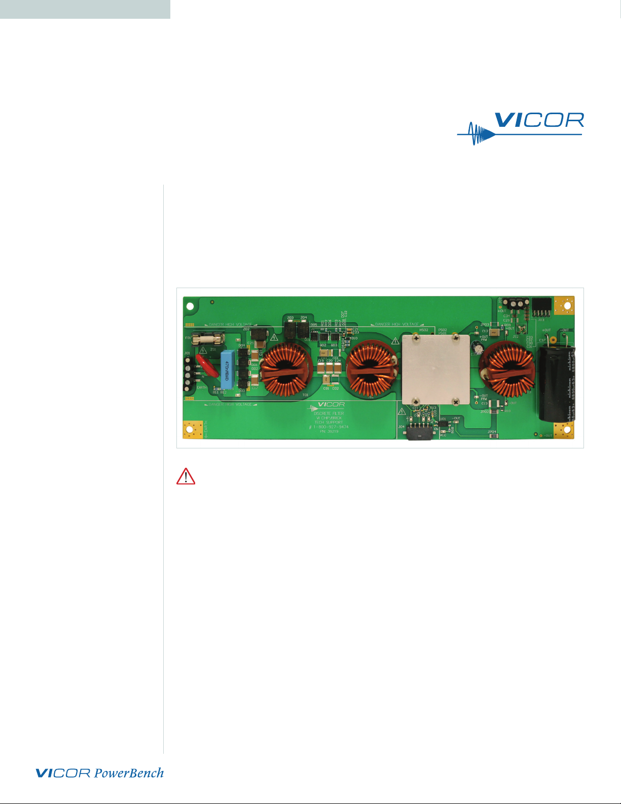
Introduction
This Evaluation Board oers a convenient means to evaluate the performance of Vicor’s
VI Brick® PFM Isolated AC-DC Converter modules with Power Factor Correction, and
has been optimized for user convenience. Refer to Table 1 for operating conditions
and limits.
This reference design contains an input line filter. It is important to remember the
response of the AC line filter is dependent upon the wiring connected to the evaluation
board. Care should be exercised to minimize stray source impedances in order to fully
exercise the features of the converter.
UG:100 vicorpower.com Applications Engineering: 800 927.9474 Page 1
Page 2
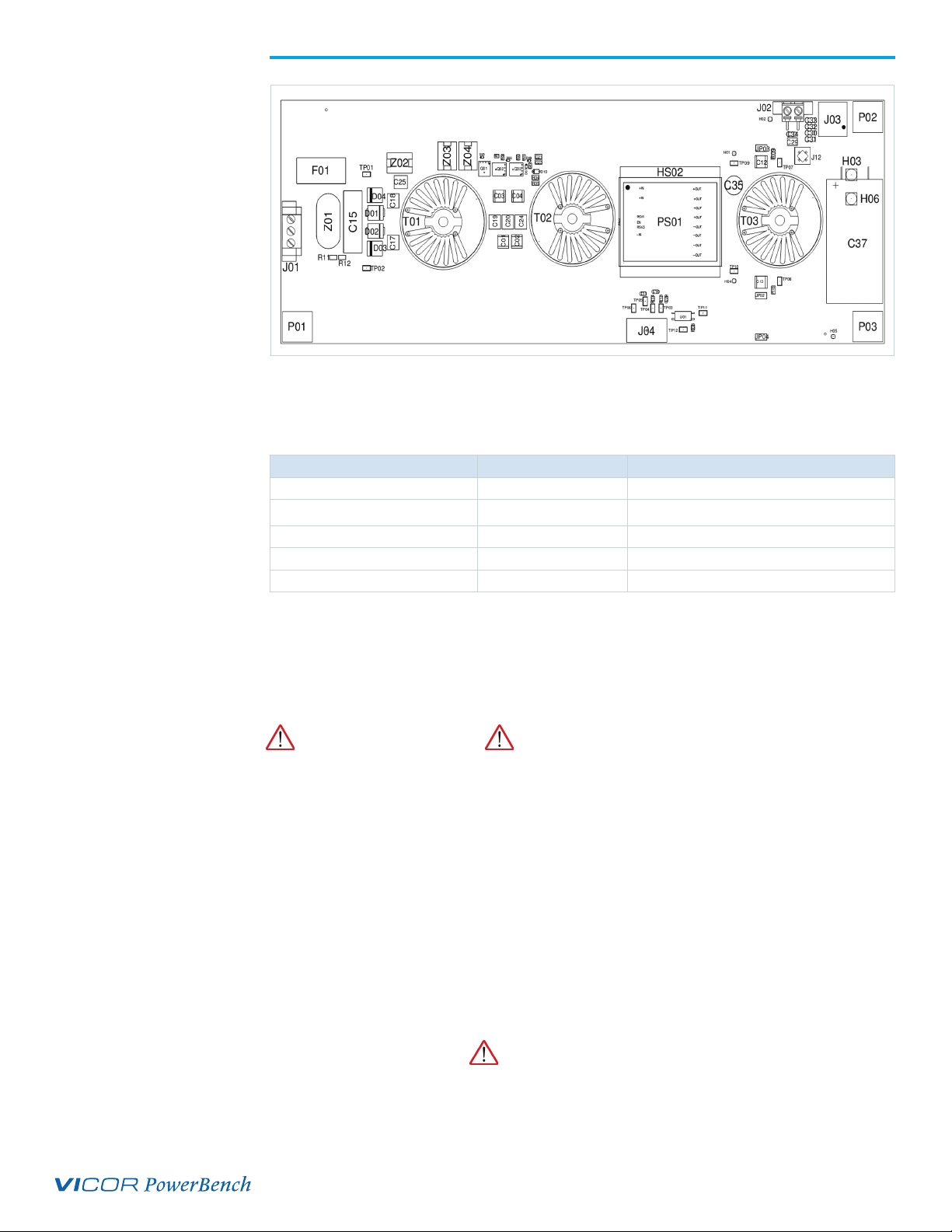
Figure 1.
VI Brick PFM AC DC Converter
Evaluation Board layout
and dimensional drawing,
component side
Basic Specifications and Operating Limits
Please use the following table for operating limits:
Table 1.
Description Specification Notes
Input range 85 – 264 Vac Universal input
Output voltage 48 Vdc Regulated
Output power 330 W Over entire input range
Operating temperature -40 to 85°C Limited by C37, T01-T03, U01, Z01-Z04
Output capacitance 6,000 to 12,000 μF 63 V rating, 20% tolerance
NOTE: Module operating temperature will depend on its Product Grade as specified in the data sheet.
Please refer to Figure 1 for locations of the input and output connections as viewed from
the component side. Wires may be soldered directly to the pads instead of ring lugs if
desired to minimize circuit impedances.
DANGER! HIGH VOLTAGE! DANGER! HOT SURFACE!
The VI Brick® AC-DC Converter Evaluation Board contains exposed hazardous
voltages. These voltages are within the area marked by the letter H on the PCB.
The VI Brick DC-DC Converter Evaluation Board may be operated at surface
temperatures which may pose a thermal hazard to the operator. Because of the thermal
and voltage hazards, be careful not to touch any exposed surface unless the power
is disconnected and the evaluation board has been given sucient time to cool. The
evaluation board is not intended for use in end item equipment.
Set Up
The Customer Evaluation Board should be set up as follows:
Note: Care should be taken to avoid reversing polarities if connecting to the opposite (solder) side of
the board.
AC Input Connections (J01) DANGER! HIGH VOLTAGE!
J01, the screw terminal connector, is for connection of AC input to the AC-DC converter
evaluation board. The interconnect leads should be appropriate for the current and
voltage supplied to the board.
UG:100 vicorpower.com Applications Engineering: 800 927.9474 Page 2
Page 3

For single phase power, connect LINE to the pin marked L, NEUTRAL to the pin marked
N and earth ground to the pin marked EARTH. Corresponding wires in an IEC cable are
brown, blue, and yellow with a green stripe.
The board can be used with three phase power. Connect LINE1 to L and LINE2 to N.
Earth ground should still be connected to the EARTH terminal of J1.
+OUT, –OUT
There are several connections available on the VI Brick AC-DC converter. Table 1 lists
the available connectors and their current rating. Do not exceed the rating of the
connector or the AC-DC converter.
Table 2.
Output Connector Ratings
Connector Rating Recommended Connection
J02 10 A Hold-up capacitor
J03 12 A (3 A/contact) Mating PRM and BCM eval boards
Ring lugs 100 A EARTH, +OUT, -OUT
2 mm holes beside C37 12 A Snap-in type capacitor 10 mm sp
Output bulk (electrolytic) capacitance must be attached across the output of the
VI Brick® AC-DC converter evaluation Board. Refer to the table above for the
appropriate range of output capacitance.
The load should be connected to +OUT and –OUT terminals of the evaluation board
with short leads of suitable gauge to carry the output current and minimize losses. A
sucient number of terminal connections should be used to ensure that no terminal
sees more than its maximum rated current. The evaluation board can be connected
directly to the application for which the AC-DC converter is intended. However the
interconnect impedances between the evaluation board and the application can greatly
aect the transient response. For applications where transient response is critical, the
user should consider mounting the VI Brick AC-DC converter directly to the target
application PCB.
Earth Connections
There is one EARTH connection available on the board, in the lower le hand corner,
P01 in the schematic diagram. The EARTH connection used for local return for the EMI
filter is the same as safety ground.
EARTH may optionally be connected to either of the AC-DC converter outputs in order
to provide a positive or negative voltage rail with respect to earth.
The default configuration of the evaluation board is to have the EARTH terminal
connected to –OUT through jumper JP02, while JP03 is unpopulated. To leave the
outputs floating, remove JP03 so that both JP02 and JP03 are unpopulated. To connect
EARTH to +OUT, remove JP02 and populate JP03.
The insulation of the AC/DC converter modules supported by this evaluation board
has not been designed to exceed SELV voltages, and should not exceed +/-60Vdc from
EARTH potential by stacking.
Input Current Measurement
A current probe can be passed around either input lead connected to the VI Brick
evaluation board. This can be used to measure DC currents and AC currents in front of
the EMI filter and transient suppression circuits.
UG:100 vicorpower.com Applications Engineering: 800 927.9474 Page 3
Page 4

Output Voltage Measurement Jack (J12)
This connector is provided to make accurate measurements of the output ripple
voltage of the VI Brick® AC-DC converter. Many types of scope probes may be directly
connected to this point if the probe is equipped with a removable plastic sheath. To
avoid creating ground loops when making measurements of the output or input
voltage, these measurements should be made separately. Clamp on ferrite chokes, such
as Digikey PN 240-2132-ND placed over the leads of passive oscilloscope probes also
help to reduce common mode high frequency switching noise pickup. A capacitor can
be added at C29 to reduce high frequency noise at the probe if necessary.
Enable (EN) DANGER! HIGH VOLTAGE!
The EN pin can be used to disable the VI Brick AC-DC converter. Connecting EN to
the –IN-PFM pin will disable the AC-DC converter. This will also clear any latching
output OVP fault if one has occurred. Note that the EN pin is referenced to the primary
(hazardous voltage) side of the converter. The EN pin can be accessed from J04, for
which a mating connector can be used. The mating connector is Molex P/N 43645-0500
with Molex 43030 series pins.
An optocoupler has been provided to allow connection to output referenced equipment.
The input to the optocoupler is connected to –OUT by default. Jumper JP04 can be
removed, allowing the customer to provide their own reference for the enable input.
This input can be floated up to +/-1000V from EARTH.
Efficiency Measurement
As the VI Brick AC-DC Converter can deliver and consume large currents, the eect of
the PCB must be considered when making an eciency measurement. When testing
your design based on this reference design, be sure to probe dierent points in the input
filter and rectifier section to verify that voltage drops are not excessive in your layout.
If eciency tests are to be automated, then Kelvin type connections are recommended
to reduce common current errors during voltage measurements.
Recommended Hardware
The hardware kit provided with the evaluation board includes the following:
n 6 #10 lock washers
n 3 #10-32 screws
n 3 #10-32 hex nuts
Ring lugs are also recommended for making output connections.
UG:100 vicorpower.com Applications Engineering: 800 927.9474 Page 4
Page 5

Figure 2.
Input, rectifier, and filter
section schematic
Theory of Operation
The schematic diagram is presented in functional blocks with text descriptions.
Component values are given in Bill of Materials, layout in PCB Layout (Figure 7).
So copies are available with download.
Input, Rectifier, and Filter Section
Input power is connected to screw terminal block J01. A 5 A fuse in F01 protects against
overcurrent. 330 W at 93% eciency draws 355W. At 85 V input, 4.17A is drawn.
Z01 is a 20 mm disk MOV that can withstand higher surges than Z02-Z04. R11 and R12
discharge the input capacitors when the line cord is pulled. Capacitors C15, C17-C20,
C24, and C25 return high frequency dierential current before it exits the line cord.
D01 through D04 form the input bridge rectifier. T01 is a high frequency common mode
inductor chosen for its high impedance up to 5 MHz. C01 and C03 are Y caps that return
common mode high frequency currents to GND (EARTH) rather than through
LINE or NEUTRAL.
Active Transient Suppression Section
Input power enters from the filter at le. C24 and C01 are repeated in the schematic
snippet. Q01 through Q03 transistors turn o during a transient event, and can block up
to 200 V each. R04/R05 through to C22 form the control mechanism for the transistors.
T02 works with the capacitors inside the VI Brick® PFM® module as part of the
conducted emissions filter.
UG:100 vicorpower.com Applications Engineering: 800 927.9474 Page 5
Page 6

Figure 3.
Active transient suppression
section schematic
Figure 4.
Output enable control
schematic
Output Enable Control
The EN pin is pulled low to disable the AC-DC converter. If pulled high to 3.3 V or
le floating, the VI Brick® PFM® will operate. A 1x5 0.100” spaced socket allows easy
connection to automated test equipment. This part of the circuit is referenced to
primary ground.
Users can connect their own secondary referenced control circuit by connecting
through the optocoupler U01, and connecting to TP12 and TP11 as needed. JP04 can be
removed to allow a floating reference for the enable input. On this TP12 input, a high
signal will result in shutdown of the AC-DC converter.
UG:100 vicorpower.com Applications Engineering: 800 927.9474 Page 6
Page 7

Output Filter Section
A common mode inductor should be used at the output to isolate switching noise from
this converter so it does not cause beat frequencies with downstream converters. The
one used in this reference design is the same used at the input so that a single part
number can be stocked. If space is at a premium, a smaller common mode inductor can
be substituted. Peak impedance should be between 500 kHz and 5 MHz.
C37 is the bulk capacitor default on this board. Hold time will be increased roughly 50%
and power factor increased roughly 0.5% if a 10,000 uF capacitor is substituted. This
default capacitor is a 25 mm x 45 mm capacitor that is laid on its side. There are also two
2 mm holes, 10 mm spacing, which can be used for snap in type electrolytic capacitors.
Diameters up to 35 mm will clear other components on the PCB. This capacitor filters
the rectified line ripple, which is twice the input frequency. RMS ripple current rating
should be 80% of output current or higher for longer lifetime. Ripple current ratings
vary as a function of ambient temperature.
C30 through C34 are output ceramic filter capacitors. There are used to reduce the
switching ripple on the 48 V bus near 1 MHz. Screw terminal J02 or 0.100” spaced J03
can be used to connect output wires to the load or connect an external capacitor.
J12 is a probe socket with a local capacitor to reduce switching noise. R09 and R10 are
used to connect either the positive or negative output terminal to GND (EARTH). Only
one should be connected at a time. Both can be removed for a floating output.
Figure 5.
Output filter section schematic
UG:100 vicorpower.com Applications Engineering: 800 927.9474 Page 7
Page 8

Bill of Materials
Thermals
For most lab environments a fan blowing across the evaluation board is recommended
See VI Brick® Thermal Management Application Note at:
www.vicorpower.com/documents/application_notes/AN200_VIBrickTherm.pdf
or contact Vicor Applications Engineering for assistance (800) 927-9474.
Ordering Information
Two models of the evaluation board are available:
Order Number Power Module On PCB AC-DC Format
PFM-DISCRETE-FILTR PS01 PFM175D480C330A00 VI Chip
PFB-DISCRETE-FILTR PS02 PF175B480C033FP-00 VI Brick
Ref. Des. Description
C01 CAPY X7R 4700pF 10% 250V 2220 Murata 490-3482-2-ND Murata GA355DR7GF472KW01L
C02 NOT APPLIED NOT APPLIED NOT APPLIED NOT APPLIED NOT APPLIED
C03 CAPY X7R 4700pF 10% 250V 2220 Murata 490-3482-2-ND Murata GA355DR7GF472KW01L
C04 NOT APPLIED NOT APPLIED NOT APPLIED NOT APPLIED NOT APPLIED
C09
CAP X7R .1uF 10% 25V 0805 Kemet 399-1170-2-ND AVX 08053C104KAT2AC10
C11
C12 CAPY X7R 4700pF 10% 250V 2220 Murata 490-3482-2-ND Murata GA355DR7GF472KW01L
C13 NOT APPLIED NOT APPLIED NOT APPLIED NOT APPLIED NOT APPLIED
C15 0.47uF/20/275VAC X2 CAP Kemet 399-5429-ND Wima MKS4 0.47/630/10 PCM 27.5
C17
C18
C19
C20
C21 CAP X7R .015uF 10% 630V 1206 TDK 445-4489-2-ND TDK C3216X7R2J153M
C22 CAP X7R 4.7uF 10% 25V 0805 TDK 445-5972-2-ND TDK CL21A475KAQNNNG
C23 CAP X7T 0.033uF 10% 630V 1206
C24
C25
C29 NOT APPLIED NOT APPLIED NOT APPLIED NOT APPLIED NOT APPLIED
C30
C31
C32
C33
C34
C35 CAP ALUM 100UF 63V 20% RADIAL Nichicon UVY1J101MPD-ND Nichicon UVY1J101MPD
C37 CAP ALEL 6800uF 20% 63V 25X50 Kemet 493-1135-ND Nichicon UVZ1J682MRD
D01
D02
D03
D04
CAP X7T 0.47uF 10% 630V 2220 TDK 445-8876-2-ND TDK C5750X7T2J474K
.060MAXHT
CAP X7T 0.47uF 10% 630V 2220 TDK 445-8876-2-ND TDK C5750X7T2J474K
CAP X7R 1.0uF 10% 100V 1206 TDK 445-4467-2-ND TDK C3216X7R2A105K
DPN 1000V 8A DO214AB Diodes Inc S8MCDITR-ND Diodes Inc S8MC-13
DPN 1000V 5A SMC *Stocked by Arrow NAC, Manufacturer: Taiwan Semiconductor, Part#: HS5M R7
Digi-Key
Manufacturer
TDK 445-7762-2-ND Yageo CC1206KKX7RZB333
Digi-Key
Part Number
Future
Manufacturer
Future
Part Number
UG:100 vicorpower.com Applications Engineering: 800 927.9474 Page 8
Page 9

Ref. Des. Description
D05
D06
D07
D08
D10 DPN 100V 200mA SOD-123 Diodes Inc BAV19W-7-F Diodes Inc BAV19W-7-F
F01 FUSE HOLDER, SMD, 5x20 Wickmann F4546-ND Schurter 31.8225
FUSE FUSE 5A 250V FAST 5X20 CARTRIDGE Littelfuse F2369-ND Littelfuse 6005.HXP
FW OUTPUT WASHER, FLATPAC Generic Generic Generic Generic
HS01 NOT APPLIED NOT APPLIED NOT APPLIED NOT APPLIED NOT APPLIED
J01 CON 3CKT TERM BLK SMD No Stock No Stock Weco 140-A-126-SMD/03
J02 CON 2 CKT TERM BLK SMD No Stock No Stock Weco 140-A-126-SMD/02
J03
J04 CONN 5POS SINGLE ROW RIGHT
J12 JACK VERTICAL MECH THRU HOLE *Stocked by Tektronix, Part#: 131-5031-00
JP02 RES 0 OHM 3/4W 5% 2010 Vishay Dale 541-0.0WTR-ND Vishay Dale CRCW20100000Z0EF
JP03 NOT APPLIED NOT APPLIED NOT APPLIED NOT APPLIED NOT APPLIED
JP04 RES 0 OHM 3/4W 5% 2010 Vishay Dale 541-0.0WTR-ND Vishay Dale CRCW20100000Z0EF
LARGE_PIN PIN .081 DIA X .21LG VICBRICK Generic Generic Generic Generic
LOCK_
WSHR
OUTPT_
NUT
PAD1 FOOT, FLIP FIXTURE Generic Generic Generic Generic
PAD2 FOOT, FLIP FIXTURE Generic Generic Generic Generic
PAD3 FOOT, FLIP FIXTURE Generic Generic Generic Generic
PAD4 FOOT, FLIP FIXTURE Generic Generic Generic Generic
PAD5 FOOT, FLIP FIXTURE Generic Generic Generic Generic
PAD6 FOOT, FLIP FIXTURE Generic Generic Generic Generic
PP1 NOT APPLIED NOT APPLIED NOT APPLIED NOT APPLIED NOT APPLIED
PP2 NOT APPLIED NOT APPLIED NOT APPLIED NOT APPLIED NOT APPLIED
PP3 NOT APPLIED NOT APPLIED NOT APPLIED NOT APPLIED NOT APPLIED
PP4 NOT APPLIED NOT APPLIED NOT APPLIED NOT APPLIED NOT APPLIED
PS01 Model Specific Vicor Model Specific Vicor Model Specific
Q01
Q02
Q03
R01 RES 12.4K OHM 1/8W 1% 0805 Vishay Dale 541-12.4KCTR-ND Vishay Dale CRCW080512K4FKEA
R02 RES 2.49K OHM 1/8W 1% 0805 Vishay Dale 541-2.49KCTR-ND Vishay Dale CRCW08052K49FKEA
R03 RES 499 OHM 1/8W 1% 0805 Vishay Dale 541-499CTR-ND Vishay Dale CRCW0805499RFKEA
R04
R05
R07 RES 2K OHM 1/8W 1% 0805 Vishay Dale 541-2.00KCTR-ND Vishay Dale CRCW08052K00FKEA
R08 RES 1K OHM 1/8W 1% 0805 Vishay Dale 541-1.00KCTR-ND Rohm MCR10EZPF1001
DZEN 16V 2% 300mW SOD523
DZEN 13V 2% 300mW SOD523
CONN 10POS 90DEG THRUHOLE
FEMALE 0.1SPC
ANGLE
PLTD #10 INT TOOTH LW PHOS/BR Generic Generic Generic Generic
OUTPUT NUT, FLATPAC Generic Generic Generic Generic
QMOS N 200V 32mR 36A 5X6 MLP Infineon BSC320N20NS3 GTR-ND No Stock No Stock
RES 2K OHM 1/4W 1% 1206 Vishay Dale 541-2.00KFTR-ND Vishay Dale CRCW12062K00FKEA
Digi-Key
Manufacturer
NXP
Semiconductor
NXP
Semiconductor
Sullins Electronics S5519-ND Sullins Electronics PPTC052LJBN-RC
Molex WM1893-ND TE Connectivity 1445057-5
Digi-Key
Part Number
BZX585-B16,115-ND
BZX585-B13,135
Future
Manufacturer
NXP
Semiconductor
NXP
Semiconductor
Future
Part Number
BZX585-B16,115
BZX585-B13,135
UG:100 vicorpower.com Applications Engineering: 800 927.9474 Page 9
Page 10

Ref. Des. Description
R09 RES 2.2 OHM 1/4W 1% 1206 Vishay Dale 541-2.20FFTR-ND Vishay Dale CRCW12062R20FKEA
R10 NOT APPLIED NOT APPLIED NOT APPLIED NOT APPLIED NOT APPLIED
R11
R12
R13
R14
SCREW SCREW, 10-32 X 3/8 PHIL PH Generic Generic Generic Generic
SMALL_PIN PIN .031 DIA X .21LG VICBRICK Generic Generic Generic Generic
STNDFF_
LGFF
T01
T03
TP01
TP02
TP03
TP04
TP05
TP06
TP07
TP08
TP09
TP10
TP11
TP12
U01 IC OPTO 70V 100mA SOP 4L No Stock No Stock Vishay TCLT-1009
Z01 VAR MOV, 300V 10KA 20mm DIA
Z02
Z04
RES 42.2K OHM 1/4W 1% 1206 Vishay Dale 541-42.2KFTR-ND Vishay Dale CRCW120642K2FKEA
RES 100 OHM 1/8W 1% 0805 Vishay Dale 541-100CTR-ND Vishay Dale CRCW0805100RFKEA
STANDOFF,.287 LG FEMALE-FEMALE Generic Generic Generic Generic
IND COM MODE 013 mH -30%+30%
016A Ø1.6mm
TEST POINT, SURFACE MOUNT Keystone 5017-ND Keystone 5017
RADIAL
VAR MOV 300V 11.5X8.3 SMD Littelfuse F3551TR-ND Littelfuse V300SM7Z03
Digi-Key
Manufacturer
*Stocked by VACUUMSCHMELZE Gmbh, part#: T60405-R6123-X616T02
Littelfuse TMOV20RP300EL2T7-ND Littelfuse TMOV20RP300E
Digi-Key
Part Number
Future
Manufacturer
Future
Part Number
UG:100 vicorpower.com Applications Engineering: 800 927.9474 Page 10
Page 11

Figure 6.
Schematic diagram
UG:100 vicorpower.com Applications Engineering: 800 927.9474 Page 11
Page 12

Figure 7.
PCB Layout
Left, top layer,
right, bottom layer.
The Power Behind Performance
Rev 1.0 12/2013 vicorpower.com Applications Engineering: 800 927.9474 Page 12
 Loading...