

Page 1

1 | 028-6145-00 November 2017
CONTENTS
Configuring and Status Display Instructions 2
Status display 2
User Interface 3
Local keypad interface 3
Configuration interface 4
VT7225 Series
User Interface Guide
For Modulating Heat Applications
November 2017
Page 2
2 | 028-6145-00 November 2017
CONFIGURING AND STATUS DISPLAY INSTRUCTIONS
Status display
The Room Controller features a two-line, eight-character display. There is a low-level
backlight level that is always active and can only be seen at night.
To turn on the back light to high level, press any key on the front panel. The back lit display
will return to low level when the Room Controller is left unattended for 45 seconds.
Occupancy Status
• Occupied, Unoccupied and Override status are displayed on the display.
LED Status
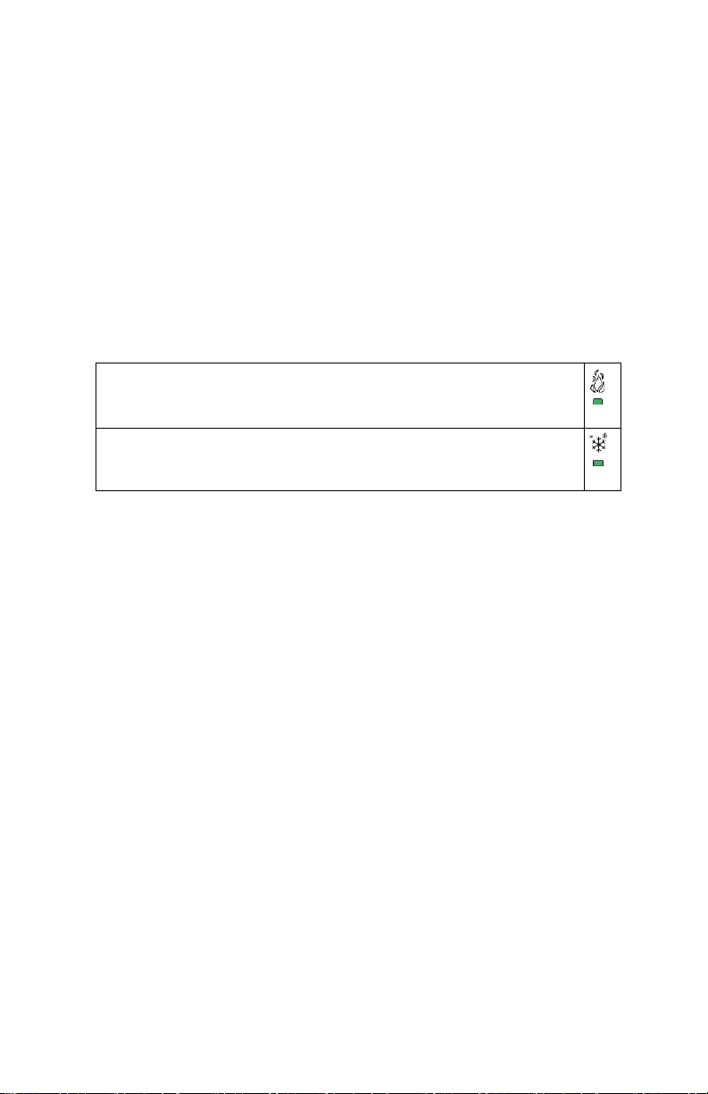
Status LED’s on the Room Control cover are used to indicate a call for heat.
When heating & reheat is ON, the HEAT LED will illuminate
Not used
Page 3
3 | 028-6145-00 November 2017
USER INTERFACE
Unoccupied mode override
An Override can be made during an unoccupied period.
Local keypad interface
4. Any setpoint change can be permanent or temporary based on configuration
parameter (Setpoint Type)
5. Lockouts of access to certain functions is made with configuration parameter
(lockout)
Unoccupied setpoints adjustments
Setting of the unoccupied setpoints is done through configuration setup only.
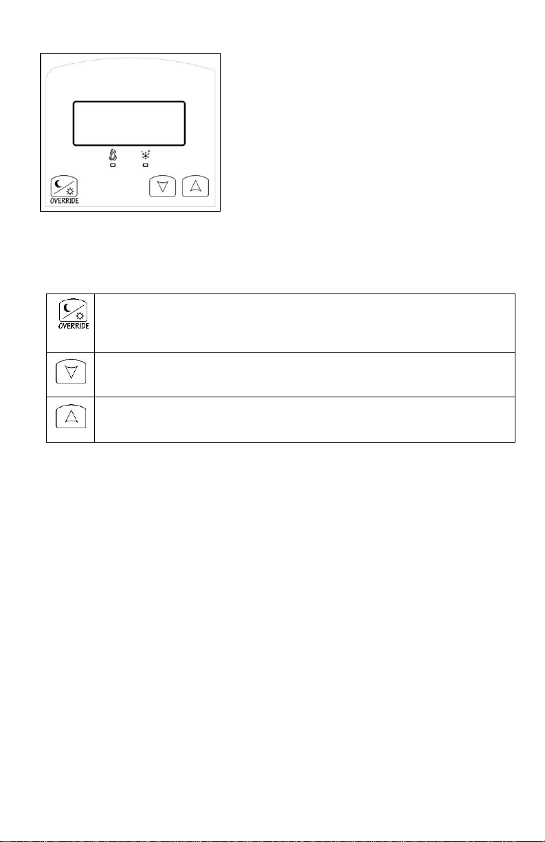
1. An Override can be made during an unoccupied period. If the
Override option is enabled in the lockout configuration pressing the
override key will resume occupied setpoints for a time specified by
parameter ToccTime
2. Decrease setpoint
3. Increase setpoint
Page 4
4 | 028-6145-00 November 2017
Installer Configuration Parameter Menu
Configuration can be done locally on the Room Controller. To enter configuration,
press and hold the left button (Override) for 8 seconds.
If a password lockout is active, “Password” is prompted. Enter password value using
the “up” and “down” arrows and press the middle button again to gain access to all
configuration properties of the Room Controller. Entering a wrong password will
prevent local access to the configuration menu.
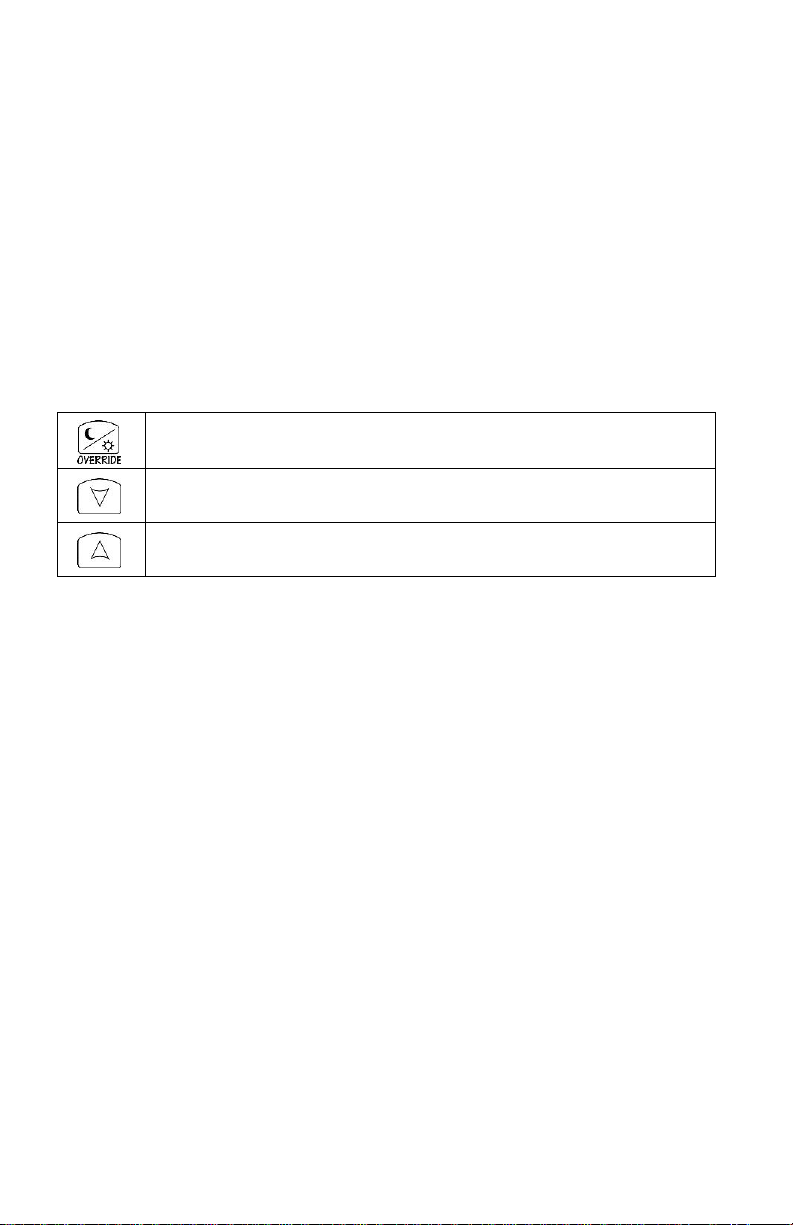
1. Press the same middle button repetitively to scroll between all the available
parameters.
2. Use the up and down key to change the parameter to the desired value.
3. To acknowledge and save the new value, press the override button again.
4. The next parameter will now be displayed.
Configuration interface
Remote NSB Operation: remote NSB timer clock input. The scheduling will now be set
as per the binary input (BI1). It provides low cost setback operation via a dry contact.
• Contact opened = Occupied
• Contact closed = Unoccupied
Supply air sensor: Used for supply air temperature control. Connecting a 10K Type II
probe to pin UI3 enables this feature. The proportional band and integral time are
automatically adjusted for supply air control. The display will show “SuppTemp”.
Pressing repetitively will individually scroll all the available parameters
Adjust value down
Adjust value up
Page 5
5 | 028-6145-00 November 2017
CONFIGURATION
PARAMETERS
DEFAULT VALUE
SIGNIFICANCE AND ADJUSTMENTS
PswrdSet
Default value = 0
This parameter sets a password access to prevent
unauthorized access to the configuration menu
parameters. A default value of “0” will not prompt a
password or lock the access to the configuration
menu.
Range: 0 to 1000
MenuScro
Default value = Off
Removes the scrolling display and displays the room
temperature to the user.
On = Scroll active
Off = Scroll not active
°C or °F
Default value = °F
Sets scale of the Room Controller
• °F for Fahrenheit scale
• °C for Celsius scale
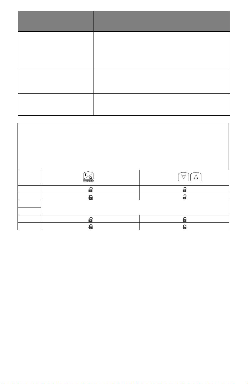
Lockout
Default value = 0 No lock
Keypad lockout levels
USER KEY FUNCTIONS
LEVEL
0
1
2
NOT USED
3
4
5
Page 6
6 | 028-6145-00 November 2017
CONFIGURATION
PARAMETERS
DEFAULT VALUE
SIGNIFICANCE AND ADJUSTMENTS
Unocc HT
Default value = 62°F (17°C)
Unoccupied heating setpoint
Range is: 0 to 180 °F (-17 to 82 °C)
Heat max
Default value = 90°F (32°C)
Maximum occupied & unoccupied heating setpoint
adjustment.
Range: 0 to 180°F (-17.0 to 82°C)
Heat min
Default value = 54°F (12 °C)
Minimum occupied & unoccupied cooling setpoint
adjustment. Heating setpoint range is:
0 to 180°F (-17.0 to 82°C)
Note: Heat max has priority over Heat min value.
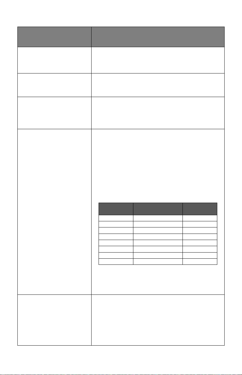
Pband
Default: 3
Adjust the proportional band used by the Room Controller
PI control loop.
Note that the default value of 3.0°F (1.2 °C) gives
satisfactory operation in most normal installation cases.
The use of a proportional band different than the factory
one is normally warranted in applications where the Room
Controller location is problematic and leads to unwanted
cycling of the unit. A typical example is a wall mounted unit
where the Room Controller is installed between the return
and supply air feeds and is directly influenced by the supply
air stream of the unit.
Note: When a supply sensor is connected to UI3, this
parameter is not used. The internal proportional band is
fixed at 50 °F (27 °C).
VALUE
°F SCALE PBAND
°C SCALE
PBAND 3 3 F
1.2 C
4
4 F
1.7 C
5
5 F
2.2 C 6 6 F
2.8 C
7
7 F
3.3 C
8
8 F
3.9 C 9 9 F
5.0 C
10
10 F
5.6 C
Set Type
Default: Permnent
Temporar: (temporary) Local changes to the heating or
cooling setpoints by the user are temporary. They will
remain effective for the duration specified by “ToccTime”.
Setpoints will then revert back to their default value after
internal timer “ToccTime” expires.
Permnent: (permanent) Any change of occupied or
unoccupied setpoints through the keypad by the user are
permanent and saved to & EEPROM
Page 7

7 | 028-6145-00 November 2017
ToccTime
Default value = 2 hours
Temporary occupancy time with occupied mode setpoints
when override function is enabled.
Range: 0-24 hours
Cal RS
Default value= 0.0 °F or °C
Offset that can be added/subtracted to the actual
displayed room temperature
Range: ± 5.0 °F, 1.0 °F increments (± 2.5 °C, 0.5 °C
increments)
Viconics Technologies Inc.
Tel.: Fax: Toll free:
www.viconics.com
 Loading...