

Page 1
XX176-00-00
VNCTRL-1 REMOTE CONTROL PANEL
Vicon Industries Inc. does not warrant that the functions contained in this equipment will meet your
requirements or that the operation will be entirely error free or perform precisely as described in the
documentation. This system has not been designed to be used in life-critical situations and must not be
used for this purpose.
Copyright © 2007 Vicon Industries Inc. All rights reserved.
Product specifications subject to change without notice.
ViconNet and its logo are trademarks of Vicon Industries Inc.
Kollector Elite and Kollector Pro and their logos are trademarks of Vicon Industries Inc.
Vicon and its logo are registered trademarks of Vicon Industries Inc.
Windows is a trademark of Microsoft Corp.
VICON INDUSTRIES INC., 89 ARKAY DRIVE, HAUPPAUGE, NEW YORK 11788
TEL: 631-952-CCTV (2288) FAX: 631-951-CCTV (2288) TOLL FREE: 800-645-9116
24-Hour Technical Support: 800-34-VICON (800-348-4266)
UK: +44 (0) 1489 566300 WEB: www.vicon-cctv.com
Vicon Part No. 8009-8176-00-00 Section 1 Rev 507
Page 2

Page 3
FCC Notice
Note: Complies with Federal Communications Commission Rules & Regulations Part 15, Subpart B for a
Class A digital device.
WARNING
This equipment generates and uses radio frequency energy and if not installed and used properly, that is, in
strict accordance with the manufacturer’s instruction, may cause interference to radio and tele vision
reception. It has been type tested and found to comply with the limits for a Class A computing device in
accordance with the specification in subpart B of part 15 of the FCC rules, which are designed to provide
reasonable protection against such interference in a commercial installation. However, there is no guarantee
that interference will not occur in a particular installation. If this equipment does cause interference to radio
and television reception, which can be determined by turning equipment off and on, the user is encouraged to
try and correct the interference by one or more of the following measures:
• Reorient the receiving antenna.
• Relocate the equipment with respect to the receiver.
• Relocate the equipment away from the receiver.
• Plug the equipment into a different electrical outlet so that the equipment and receiver
are on different branch circuits.
If necessary, the user should consult the dealer or an experienced radio/television technician for additional
suggestions.
The user may find the following booklet prepared by the Federal Communications Commission helpful:
“Interference Handbook, Bulletin CIB-2”
This booklet is available from the U.S. Government Printing Office, Superintendent of Documents, Mailstop
SSOP, Washington, D.C. 20402-9328, ISBN 0-16-045542-1.
Warning: Power must be removed from this unit before removing circuit modules or ribbon cables.
Caution: This unit contains circuit cards with integrated circuit devices that can be damaged by static
discharge. Take all necessary precautions to prevent static discharge
XX176-00-00 Rev 507 VNCTRL-1 Remote Control Pan el • i
Page 4
Important Safeguards
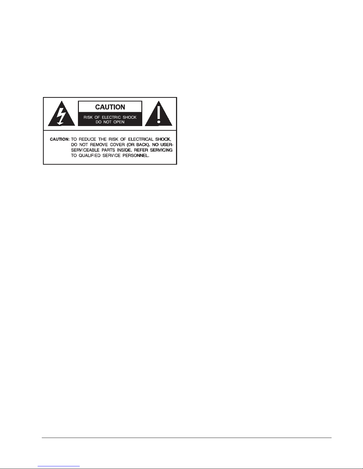
GRAPHIC SYMBOL EXPLANATION
The lightening bolt symbol alerts the user to the presence of
dangerous voltage that may present the risk of electric shock.
The exclamation point symbol alerts the user to the presence
of important operating and maintenance instructions.
1. Read Instructions - Read all safety and operating
instructions before the product is operated.
2. Retain Instructions - Retain all safety and operating
instructions for future reference.
3. Heed Warnings - Pay attention to all product warnings.
4. Follow Instructions - Follow all operating instructions.
5. Cleaning -(Do not use caustic, abrasive or aerosol
cleaners)
a) For units that CAN BE DISCONNECTED from the power
source, use a damp cloth for cleaning.
units that CANNOT BE DISCONNECTED from the
b) For
power source, use a damp cloth for cleaning and do not
allow moisture or liquids to enter vents.
6. Attachments - Use only UL Listed Vicon recommended
attachments to prevent unit damage and personal injury.
7. Water and Moisture - Use only products designed for
outdoor environments where they will be exposed to water or
moisture.
8. Accessories - Do not place the unit on an unstable surface
to a vo id fa ll in g. Use only UL Listed Vicon recommended mounting
accessories.
9. Ventilation - Do not block ventilating slots and openings as
they ensure reliable operation. Do not place the unit near a
heat source or into an enclosure unless recommended by
Vicon.
10. Power Sources - The product should only be operated
from the recommended power source. Use only a UL Class 2
indoor/dry or Class 3 outdoor/wet power supply.
11. Grounding - Only products equipped with a 3-prong
grounded plug should be inserted into a grounded power outlet.
Contact an electrician to replace an obsolete outlet. Do not
force a plug into a non-grounded outlet.
12. Power Cord Protection - Power supply cords should not
be routed in trafficked areas or in tight spaces where they will
be pinched or used to bear weight. Allow some slack in the
cord where it enters the unit.
13. Outdoor Cable Grounding - Use only grounded outdoor
cables to protect against voltage surges and static charges.
Section 810 of the National Electrical Code, ANSI/NFPA 701984, provides information on proper grounding of the lead-in
wire to an antenna discharge unit, size of grounding conductors
and the requirements of grounding electrodes.
14. Lightning - Disconnect the product from its power source
and cable system when possible to prevent damage due to
lightning and power-line surges.
15. Power Lines - Do not locate outside cables over power or
utility lines where they can fall and make direct contact. Contact
with power lines can be fatal.
16. Overloading - Do not overload wall outlets and extension
cords to prevent risk of fire and electric shock.
17. Object and Liquid Entry - Never probe through, or spill
liquid into, enclosure openings to prevent risk of fire or electric
shock.
18. Servicing - Refer all servicing to qualified service
personnel.
19. Damage Requiring Service - Obtain service when:
a) The power-supply cord or plug is damaged.
b) Objects have fallen or liquid has been spilled into the
product.
c) The product is not designed for outdoor use and has been
exposed to water or moisture.
d) The product does not operate per the operating
instructions. Perform Vicon recommended adjustments,
modifications and troubleshooting only to avoid unit
damage and personal injury.
e) The product has been dropped.
f) The product shows a significant change in performance.
20. Replacement Parts - Use only Vicon specified
replacement parts or an approved equivalent to prevent unit
damage and injury.
21. Safety Check - Request safety checks to be performed
following repair or maintenance to verify proper operation.
22. ESD Precaution - Take all normal electrostatic discharge
precautions to avoid component damage during installation and
operation.
23. For 230 VAC Devices Only - When the disconnect device
is not incorporated in the equipment or when the plug on the
power supply is intended to serve as the disconnect device,
follow the guidelines below:
a) For permanently connected 230 VAC units, a readily
accessible disconnect device must be incorporated into
the site wiring.
b) For 230 VAC units with a plug, the outlet must be installed
near the unit and be easily accessible.
ii • XX176-00-00 Rev 507 VNCTRL-1 Remote Control Panel
Page 5

Important Notice
This manual is delivered subject to the following conditions and restrictions:
This manual contains proprietary information belonging to Vicon. Such information is supplied solely for the
purpose of assisting explicitly and properly authorized users of the ViconNet system.
No part of its contents may be used for any other purpose, disclosed to any person or firm or reproduced by
any means, electronic or mechanical, without the express prior written permission of Vicon.
The text and graphics are for the purpose of illustration and reference only. The specifications on which they
are based are subject to change without notice.
Information in this manual is subject to change without notice. Corporate and individual names and data used
in examples herein are fictitious unless otherwise noted.
Copyright ©2007 Vicon. All rights reserved.
ViconNet, Kollector, Vicon and its logo are registered trademarks of Vicon Industri es Inc.
Other company and brand products and service names are trademarks o r registered trademarks of their
respective holders.
To ensure that the VNCTRL-1 is protected during a power surge or failure and that no important data is lost, it
should be connected to an uninterruptible power source (UPS) before use.
XX176-00-00 Rev 507 VNCTRL-1 Remote Control Panel Important Notice • iii
Page 6

Table of Contents
FCC Notice............................................................................................................................I
Important Safeguards.........................................................................................................II
Important Notice.................................................................................................................III
Chapter 1 - Introduction......................................................................................................5
Accessory Kit..................................................................................................................................................6
Unpacking and Inspection.............................................................................................................................6
Chapter 2 - Installation........................................................................................................7
Unpacking the Remote Control.....................................................................................................................7
Required Items for Installation......................................................................................................................7
Unit Components............................................................................................................................................7
Panel Connectors and Indicators..................................................................................................................7
Setting the DIP Switches ...............................................................................................................................8
Mounting .......................................................................................................................................................10
Installing the VNCTRL-1...............................................................................................................................10
Connecting the Cabling ..............................................................................................................................10
Connecting the Power Supply ....................................................................................................................11
ViconNet Setup...........................................................................................................................................13
Chapter 3 - Operation........................................................................................................15
Powering-On the Remote Control...............................................................................................................15
Powering-Off the Remote Control ..............................................................................................................15
Operating the Remote Control Panel .........................................................................................................15
Appendix 1.........................................................................................................................17
Chapter 4 - Maintenance...................................................................................................20
Chapter 5 – Shipping Instructions...................................................................................20
Chapter 6 – Twisted-Pair Cable Recommendations.......................................................21
Chapter 7 – Technical Information...................................................................................22
Vicon Standard Equipment Warranty..............................................................................23
iv • Table of Contents XX176-00-00 Rev 507 VNCTRL-1 Remote Control Panel
Page 7

Chapter 1 - Introduction
The information in this manual covers the installation and operation of the VNCTRL-1 Remote Control Panel.
This system should only be installed by a qualified technician using common hand tools and approved
materials and wiring practices in accordance with the National Electrical Code ANSI/NFPA 70, state and local
wiring codes.
Note: Read all instructions before beginning the installation.
The VNCTRL-1 Remote Control Panel is specifically designed for interview room applications to allow direct
control of the Kollector/ViconNet recording device. It is setup through the ViconNet application screen on the
Kollector DVR/NVR workstation. After it is setup at the PC site, it can be installed in any remote location to
record. When recording is complete, the event can then be burned onto a DVD for ar chiving. The event is
recorded on the DVD burner(s) of the DVR/NVR; if the DVR/NVR has more than one burner, the DVDs will
burn simultaneously.
The unit is operated by simple front panel controls. Recording begins with the simple press of a RECORD
START button and ends by pressing STOP. Burning a DVD is as easy as pressing COPY START. As an
added safety feature, the STOP/ABORT button must be depressed for 5 seconds before recording or copying
stops, to avoid an accidental push of the button. There are LED indicators to display when the unit is
recording or copying. STATUS LEDs alert the user if the unit is on line or if there is any failure situation. There
is also a MUTE button to silence the audible alarm and other beeps the unit makes during operation. An LED
displays when this is activated.
The VNCTRL-1 communicates with the Kollector DVRs/NVR workstations via a serial interface on the rear
panel. The unit can communicate over RS-422/RS-485. The rear panel also has a relay output (N.O./N.C.) to
drive a remote indicator, such as a light, to indicate recording is in progress.
The VNCTRL-1 may be mounted on a desktop or it can be rack mounted in a standard 19-inch rack.
The VNCTRL-1 complies with CE and meets requirements for an FCC Class A computing device.
Vicon strongly recommends the use of line conditioners, voltage regulators an d uninterruptible power supply
(UPS) systems in the electrical power service.
XX176-00-00 Rev 507 VNCTRL-1 Remote Control Panel Chapter 1 - Introduction • 5
Page 8
Accessory Kit
The provided accessory kit contains necessary items needed to install and wire the remote control panel
during installation. A V422-CONV (product code 6649-10) is required for RS-232 connection to the DVR/NVR.
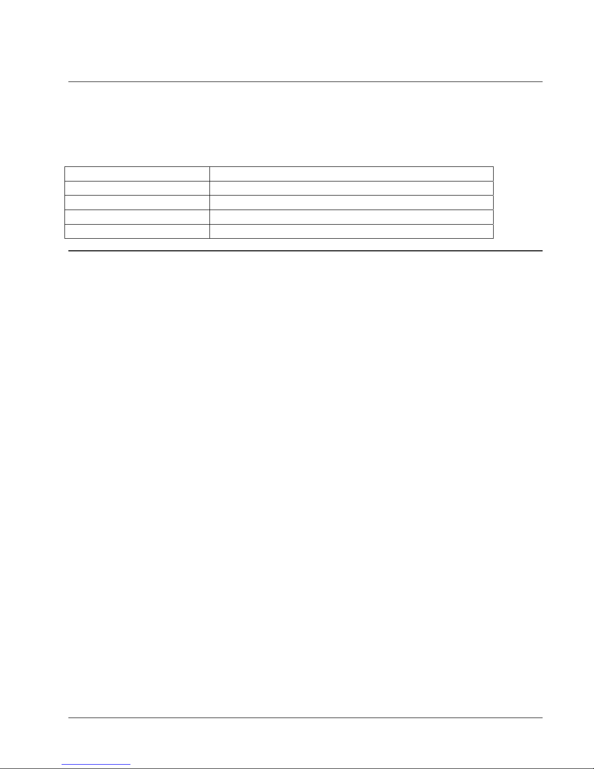
Table 1-1: Accessory Kit
Part Description
Installation and Operation Manual Provides instructions on installation, configuration and operation.
Line cord Provides power to the unit.
9-pin D-shell adapter Used to adapt the 9-pin connector to a terminal block connector
9-pin D-shell gender changer Used to change rear panel 9-pin female connector to a male connector
Unpacking and Inspection
All Vicon equipment is tested and inspected before leaving the factory. It is the carrier’s responsibility to
provide suitable delivery.
Inspect the cartons upon delivery and, if damage is present, make detailed notes on the carrier’s bill. Then,
obtain the carrier agent’s signature and file a damage claim as soon as possible.
Open the cartons and inspect the equipment for damage. Save the cartons and packing mat erial. If damage is
present, contact the carrier and file a damage claim immediately. If the equipment must be returned for repair,
follow the instructions in Shipping Instructions.
6 • Chapter 1 - Introduction XX176-00-00 Rev 507 VNCTRL-1 Remote Control Panel
Page 9
Chapter 2 - Installation
Unpacking the Remote Control
Carefully open the carton. Remove the accessory kit and the VNCTRL-1 from the box and place them on a
large, flat working surface. Open the accessory kit and verify the contents against the list in Table 1-1.
Required Items for Installation
To properly install the remote control there must be simple hand tools available such as a screwdriver,
wrenches, pliers and wire cutters/strippers.
Unit Components
This section describes the VNCTRL-1 front and rear panels.
Panel Connectors and Indicators
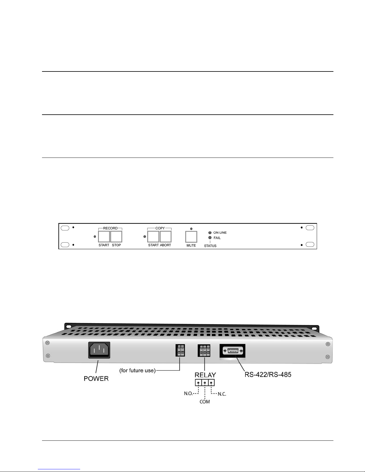
The following pictures show the VNCTRL-1 front and rear panels. Each panel component is described below.
Figure 2-1: Front Panel Layout
The front panel provides a RECORD START button and RECORD STOP button. A COPY START begins
burning a DVD. COPY ABORT stops the copying process. There are LED indicators to displa y when the unit
is recording or copying. STATUS LEDs alert the user if the unit is On Line or if there is any failure situation.
There is also a MUTE button to silence the audible alarm and other beeps the unit makes during operation.
An LED displays when this is activated.
Figure 2-2: Rear Panel Layout
XX176-00-00 Rev 507 VNCTRL-1 Remote Control Panel Chapter 2 - Installation • 7
Page 10
The VNCTRL-1’s rear panel contains the following components:
Power: A standard 3-conductor female socket.
RS-422/RS-485 Port: A 9-pin D-shell connector for communication s. A V422-CONV is required for RS-232
connection to the DVR/NVR.
Relay Port: A 3-position terminal block used for remote Record indication (N.O./N.C.). The relay is activated
when the Kollector/NVR indicates it is in Record mode.
2-Pin Terminal Block: For future use.
Setting the DIP Switches
The VNCTRL-1 has two (2) DIP switches. The DIP switches are accessed by removing the two (2) screws
that secure the top cover and carefully removing the cover.
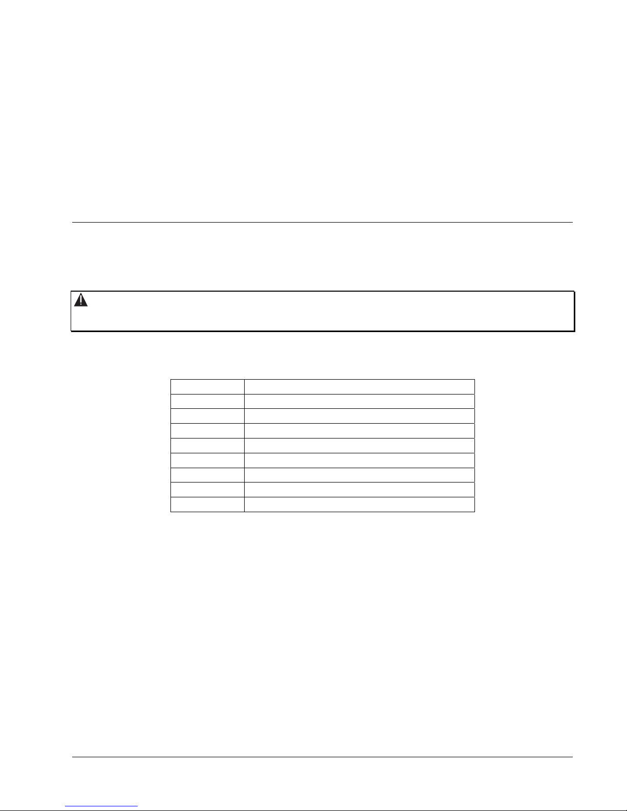
Warning: Be sure to disable the AC power before removing cover to prevent installer injury an d damage
to the unit.
SW1 has 8 poles and SW2 has 4 poles. The switches have the following functions:
SW1 – Address/Audible Notification/Test
Pole Function
1 Address Bit 0
2 Address Bit 1
3 Address Bit 2
4 Address Bit 3
5 Address Bit 4
6 Audible alarm muted when ON
7 Key beep muted when ON
8 Test mode when on (factory use only)
8 • Chapter 2 - Installation XX176-00-00 Rev 507 VNCTRL-1 Remote Control Panel
Page 11
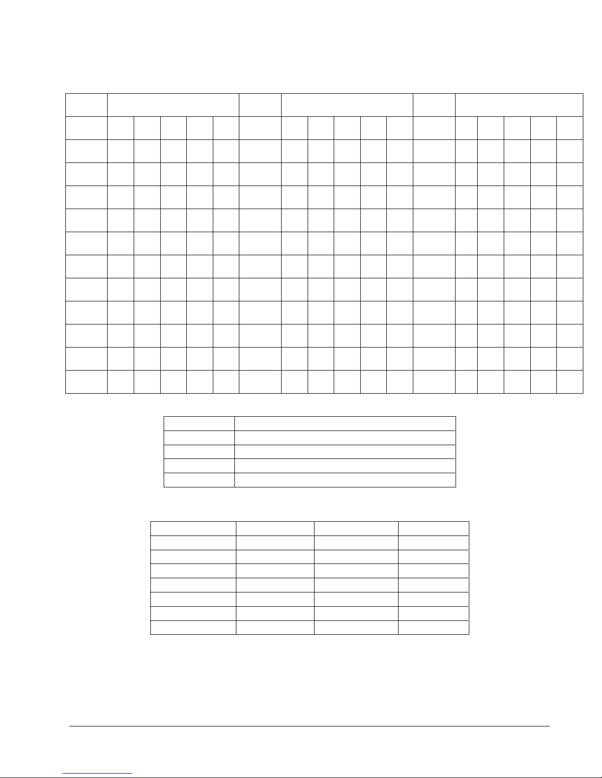
Setting Addresses
Address Pole Address Pole Address Pole
5 4 3 2 1 5 4 3 2 1 5 4 3 2 1
1 OFF OFF OFF OFF OFF 12 OFF ON OFF ON ON 23 ON OFF ON ON OFF
2 OFF OFF OFF OFF ON 13 OFF ON ON OFF OFF 24 ON OFF ON ON ON
3 OFF OFF OFF ON OFF 14 OFF ON ON OFF ON 25 ON ON OFF OFF OFF
4 OFF OFF OFF ON ON 15 OFF ON ON ON OFF 26 ON ON OFF OFF ON
5 OFF OFF ON OFF OFF 16 OFF ON ON ON ON 27 ON ON OFF ON OFF
6 OFF OFF ON OFF ON 17 ON OFF OFF OFF OFF 28 ON ON OFF ON ON
7 OFF OFF ON ON OFF 18 ON OFF OFF OFF ON 29 ON ON ON OFF OFF
8 OFF OFF ON ON ON 19 ON OFF OFF ON OFF 30 ON ON ON OFF ON
9 OFF ON OFF OFF OFF 20 ON OFF OFF ON ON 31 ON ON ON ON OFF
10 OFF ON OFF OFF ON 21 ON OFF ON OFF OFF 32 ON ON ON ON ON
11 OFF ON OFF ON OFF 22 ON OFF ON OFF ON
SW2 – Baud Rate/Reset
Pole Function
1 Baud rate setting - Bit 0
2 Baud rate setting - Bit 1
3 Baud rate setting - Bit 2
4 Reset on prolonged communication fail when ON
The Baud Rate settings are as follows:
Baud Rate Bit 2 Bit 1 Bit 0
600 OFF OFF OFF
1200 OFF OFF ON
2400 OFF ON OFF
4800 OFF ON ON
9600 ON OFF OFF
19200 ON OFF ON
38400 ON ON OFF
The factory default settings are 9600 baud, reset on prolonged communications fail ON, address 1, audible
alarm enabled, and key beep enabled.
XX176-00-00 Rev 507 VNCTRL-1 Remote Control Panel Chapter 2 - Installation • 9
Page 12
When replacing the cover, be sure that the tongue in the center of the rear edge goes over the lip on the rear
panel to properly secure the cover. Replace the two (2) screws secure the cover.
Mounting
The VNCTRL-1 can be mounted in a standard 19-inch (483 mm) wide vertical rack. Use hard ware appropriate
for the selected rack mount. The VNCTRL-1 can also rest on a clean and dry flat surfa ce, like a desk or
tabletop. There must be an area of no less than 3 in. (76 mm) left around the exterior to provide suitable
airflow for cooling. Do not place items on the cover.
Installing the VNCTRL-1
After the unit is mounted, follow the steps in this section to install the unit.
IMPORTANT NOTES:
The connection of external hardware may require simple hand tools.
Warning: Disable the AC power to prevent installer injury and damage to the unit.
Before beginning the hardware installation, ensure that the following environmental conditions have been met:
• The surface on which the VNCTRL-1 is to be placed must be level, clean and dry.
• The room or area temperature is climate controlled for human occupancy.
Connecting the Cabling
This procedure describes the required cabling that must be installed in order to use the remote control.
To connect the cabling:
1. Using a twisted-pair cable as defined in the section Twisted-Pair Cable Recommendations, prepare a
dual shielded twisted-pair type cable by stripping the ends back for use.
2. Insert the 9-pin gender changer into the female 9-pin D-shell connector. Then connect the 9-pin adapter
to the gender changer to create terminal board connection. Connect the wires according to the table
below.
3. To convert the communications to RS-232, install the other end of this cable into a V422-CONV that will
then connect to the Kollector/NVR workstation. See Installation Diagram, Figure 2-3. The Vicon V422CONV RS-422 to RS-232 converter can be used for applications requiring use of a serial (COM) port for
control. The converter plugs directly into the SERIAL port (DB-9 connector) and its terminal block wired
directly to the remote control panel.
10 • Chapter 2 - Installation XX176-00-00 Rev 507 VNCTRL-1 Remote Control Panel
Page 13
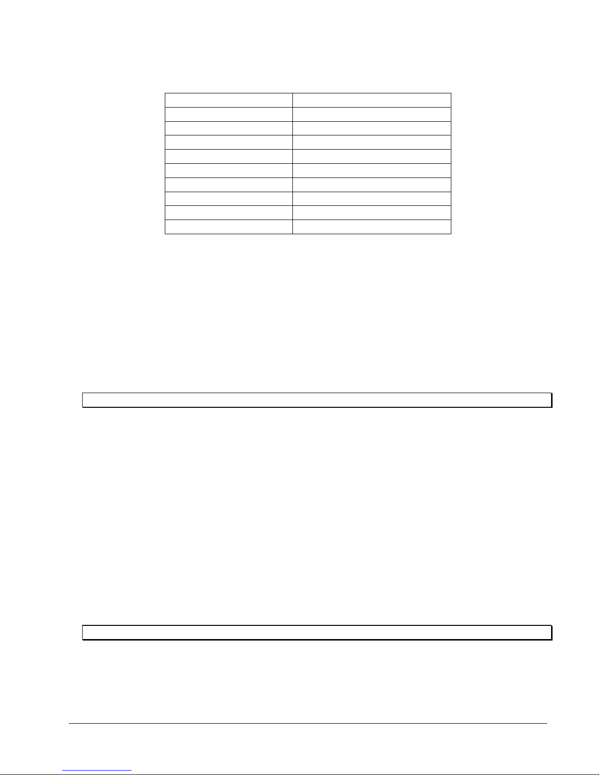
RS-485/422 Connections (Refer to Figure 2-3)
Pin Function
1 Not used
2 Not used
3 Not used
4 Not used
5 Not used
6 RS-422 Data Out +
7 RS-422 Data Out 8 RS-422 Data In +
9 RS-422 Data In -
To connect a relay to the VNCTRL-1:
4. Locate the relay cable(s) near the control. These wires (pairs) will be connected to the 3-pin terminal
block connector. The relay provides both normally open and normally closed contacts. The contacts are
rated at 500 mA at 30 VDC and are protected from voltage transients by MOV resistors.
Common is connected to Normally Open.
5. Connect one wire to the N.O. (left terminal) connection on the terminal block. Refer to Figure 2-2.
6. Connect the other wire to the N.C. (right terminal) connection. The center terminal is Common.
7. Connect the other end of this cable to the appropriate alarm output (N.O. or N.C. dry contact).
In Record mode,
Note: Users may select N.O. and N.C. according to the sensor type being installed.
When replacing the terminal block after wiring, make sure that the dovetails are properly engaged so mating
halves remain aligned.
Connecting the Power Supply
To ensure that the VNCTRL-1 is protected during a power surge or failure and that no data is lost, it should be
connected to an uninterruptible power source (UPS) before use. The power supply must be supplied by the
customer.
To connect the UPS:
1. Place the VNCTRL-1 near the power supply. Connect the supplied line cord to the UPS power receptacle.
2. Connect the UPS power cord to the wall outlet.
3. Power on the UPS and ensure that it is working properly.
NOTE: Refer to your UPS device’s User Manual for details on proper connection.
XX176-00-00 Rev 507 VNCTRL-1 Remote Control Panel Chapter 2 - Installation • 11
Page 14
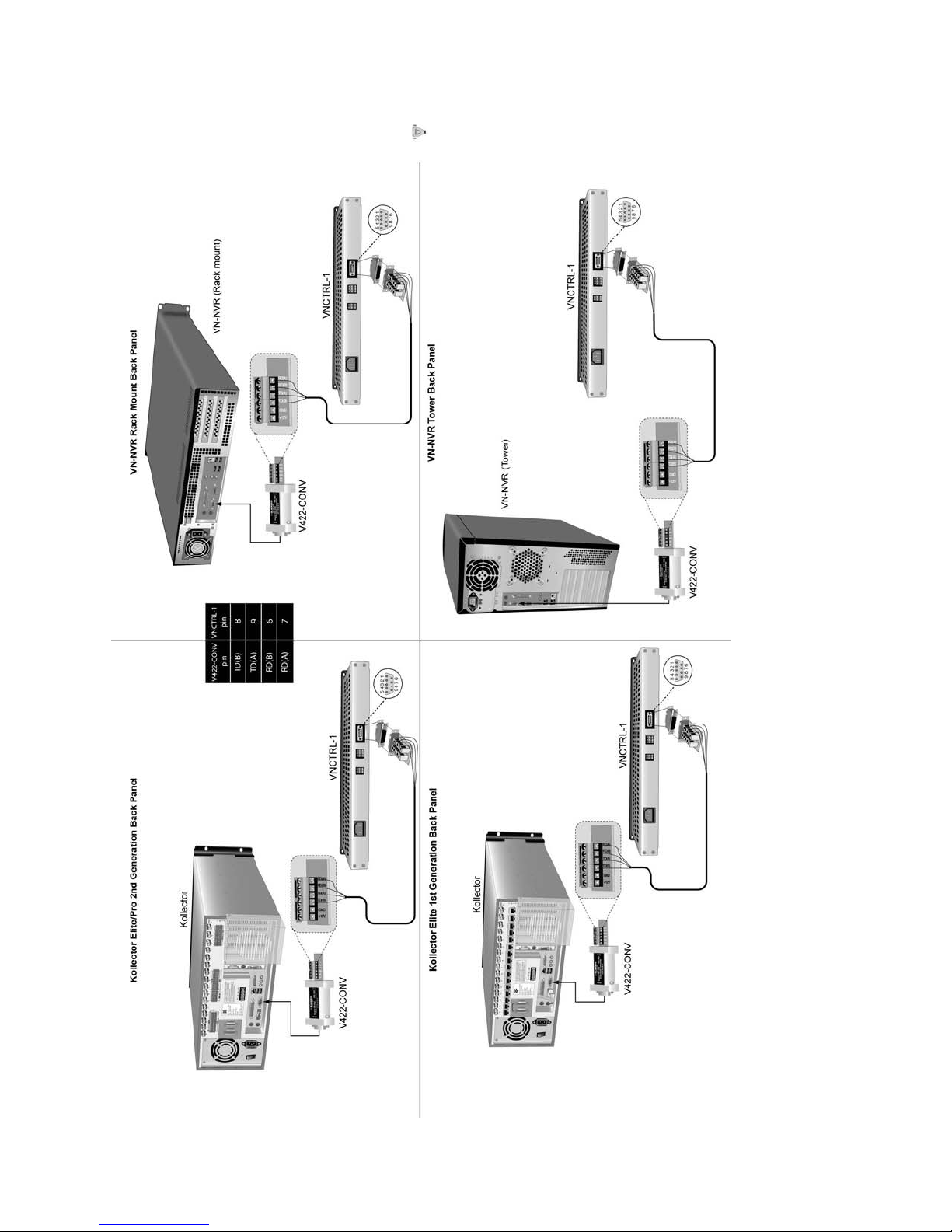
Figure 2-3
Installation Diagram
12 • Chapter 2 - Installation XX176-00-00 Rev 507 VNCTRL-1 Remote Control Panel
Page 15
ViconNet Setup
It is necessary to install a software driver to enable the remote control. The minimum driver requirement is the
ViconNet driver, revision 912. All later revision drivers will also support remote control operation. The driver
must be installed prior to hardware connection. Refer to Vicon manual XX113-56 or later for details on driver
installation.
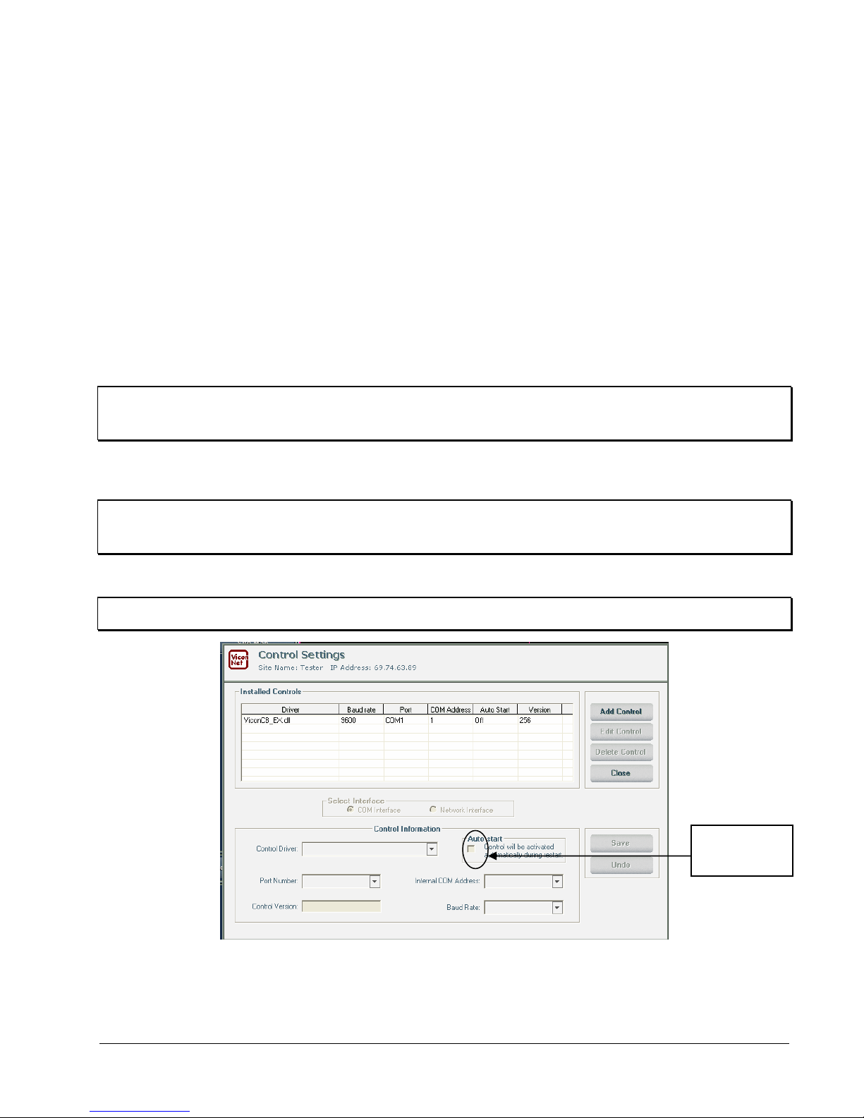
ViconNet is setup to use the remote control in Main Settings RS232/422/485 Controls. The COM port is
configured in ViconNet Setup, selecting the available COM port for the PC and the “Internal COM Address”,
which is remote control address programmed in the remote control.
The internal comport must not conflict
with any camera addresses. Baud rate is usually 9600 baud.
● The Baud Rate and COM Address (9600 and 1 in screen example below) in ViconNet and VNCTRL-1
should match.
NOTE: COM address can be any address 1-64. When setting address, make sure it does not conflict with a
camera PTZ address.
● For the 2
● For the 1
● For the VN-NVR back panel: Under Port COM 1 must be selected.
nd
generation KE back panels: Under Port COM 1 must be selected.
st
generation KE back panels: Under Port COM 2 must be selected.
Note: The V422-CONV RS-422 to RS-232 converter must be used and plugs into the open COM port on rear
of the Kollector as illustrated in Figure 2-3.
Note: Do NOT check the box for Auto start.
Sample ViconNet Setup Screen
Do NOT check
XX176-00-00 Rev 507 VNCTRL-1 Remote Control Panel Chapter 2 - Installation • 13
Page 16
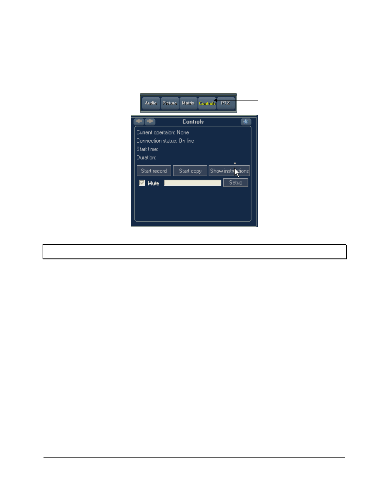
After running the ViconNet application and logging in, you will need to click the Controls button and select the
local system to start the control panel. When the VNCTRL-1 is recognized in the ViconNet system, the
following displays in the Control dialog Display area on the ViconNet Main Window. The only active buttons
on this display are Show/Hide instructions and Setup. Start record and Start copy must be activated from the
remote VNCTRL-1. The connection status displays if the unit is On line or Off line.
Controls
Button
Note: The VNCTRL-1 will have to be started each time the application is started or logged off.
After ViconNet is setup for the unit, it is necessary to configure the software files related to the VNCTRL-1
Control Panel. Refer to Appendix 1 for this procedure.
14 • Chapter 2 - Installation XX176-00-00 Rev 507 VNCTRL-1 Remote Control Panel
Page 17
Chapter 3 - Operation
Powering-On the Remote Control
To power on the remote control:
1. Verify that the control is set up as detailed in Chapter 2, Installation.
2. Connect the power supply to the VNCTRL-1. When the unit is powered up the yellow LED on the Main
PCB inside the unit will light for 1 second
processor is operating properly. When the unit is powered up all the LEDs are briefly lit and the unit
sounds as a test.
Powering-Off the Remote Control
To power off the remote control:
With the remote control operational, disconnect the power supply.
Operating the Remote Control Panel
After running the ViconNet application and logging in, you will need to click the Controls button and select the
local system to start the control panel. The VNCTRL-1 is operated with easy-to-use front panel controls:
RECORD START, RECORD STOP, COPY START, COPY ABORT, and MUTE. LED displays are provided
for Recording On, Copying On, Muted, On-Line, and Fail. An audible sound is provided, if ena bled. Whenever
a key is pressed there is a short beep of acknowledgement.
then flash briefly once per second. This LED indicates that the
RECORD START/STOP: Recording begins with the simple press of the RECORD START button and end s by
pressing STOP. As an added safety feature, the RECORD STOP button must be depressed for 5 seconds before
recording stops, to avoid an accidental push of the button.
Recording ON LED: This indicates the recording state as relayed by the Kollector. There may be a short delay
between the button push and the LED indicating that the Kollector has gone into the state desired.
COPY START, COPY ABORT: Burning a DVD is as easy as pressing COPY START. As an added safety
feature, the ABORT button must be depressed for 5 seconds before copying stops, to avoid an accidental
push of the button.
Note: Media must be in DVD burner before recording begins. Only a DVD can be used – no CDs.
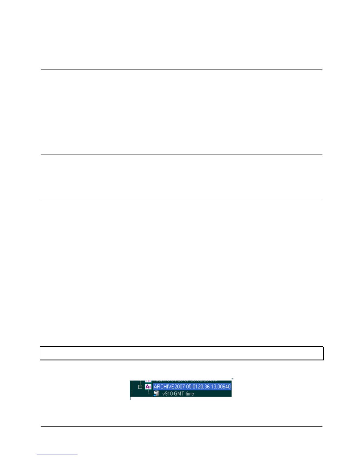
An archive will be created on the DVD in the ViconNet format (see example below).
XX176-00-00 Rev 507 VNCTRL-1 Remote Control Panel Chapter 3 - Operation • 15
Page 18
The RECORD START and COPY START buttons are interlocked. If COPY START is pressed while in
Recording mode, an error sound (approximately 1 second) is emitted and the co mmand is not sent to the
Kollector. The same interlock applies if RECORD START is pressed while in Copying mode.
MUTE: This button silences the audible alarm and other beeps the unit makes during operation. An LED
displays when this is activated
.
FAIL LED: If the Kollector is not operating, the Fail LED will remain lit. During this time, the Record, Copy and
Mute LEDs are extinguished.
Note: In some cases the Fail LED continually flashes even if the unit seems to be functioning well. In this
case, ignore the flashing and use audible sounds to indicate true problems.
ON-LINE LED: When the Kollector starts to respond, the Fail LED is extinguished and the green On-Line LED
will flash briefly whenever the control panel successfully polls the Kollector. This is normally at 5 second
intervals. In this state the Record, Copy and Mute LEDs indicate the actual state of the Kollector.
If the Kollector ceases to respond or the Kollector sends an error message, the unit will sound continuously
and the Fail LED flashes. The audible indicator may be silenced by pressing the MUTE key. If the unit is
actually sounding, the MUTE key simply mutes the local audible indicator; it does not in this case send a
command to the Kollector.
If the source of the error has not been cleared then when the MUTE key is pressed to silence the sound, the
red Fail LED will remain lit. Note that if polling is still taking place while there is another source of error, the
green On-Line LED will still flash on each poll.
If the internal DIP switch is set for reset on prolonged communication fail, and there is no communication from
the Kollector, then the processor in the control panel will reset approximately once per minute. The reset
gives the same indications as the unit being powered up.
16 • Chapter 3 - Operation XX176-00-00 Rev 507 VNCTRL-1 Remote Control Pan el
Page 19
Appendix 1
After the VNCTRL-1 is installed and setup, the software must be configured. Perform the following steps for
the configuration of the software files related to the VNCTRL-1 remote control panel.
1. Restart the ViconNet application and log in.
2. Click the Controls button and select the local unit and VNCTRL-1.
3. The Instruction Window can be moved to the side and/or click on Hide Instructions to remove it
4. Make sure the device shows an online status; if it doesn’t, verify that the correct COM address and baud
rate setting are being used (see ViconNet Setup).
5. Close the ViconNet application and exit to the operating system.
At this stage the configuration files have been created in the following directory:
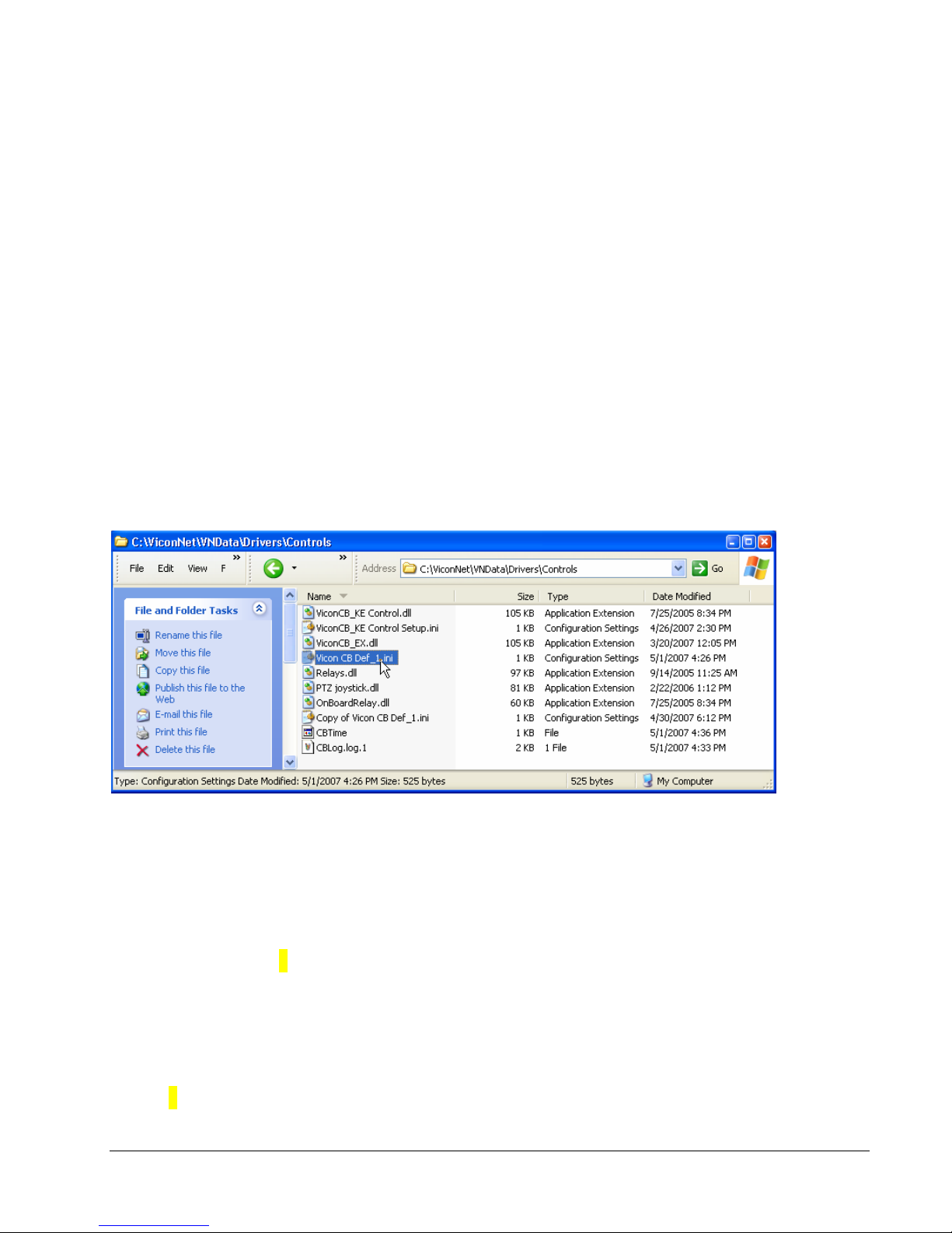
C:\ViconNet\VNData\Drivers\Controls
You will need to edit the following file: Vicon CB Def_1.ini
The file contains the following sections that require editing:
1. [Sites]
Comment-NumberOfTransmitters=Number Of Transmitters To Record From
NumberOfTransmitters=1
• This section indicates the number of video/audio sources this unit will need to record. If you have a
single DVR it will be 1 transmitter, even if you are recording more than 1 camera/mic from it. Two IP
cameras will be considered 2 transmitters.
2. [Site_1]
XX176-00-00 Rev 507 VNCTRL-1 Remote Control Pan el Appendix 1 • 17
Page 20
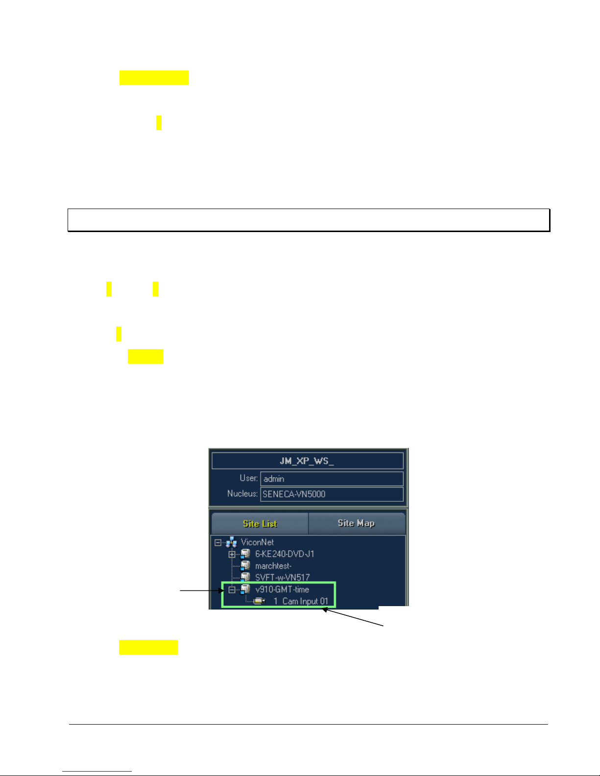
SiteName=V910-GMT time
Comment-NumberOfDevices=Number Of Devices To Record From The Site Above
NumberOfDevices=1
• This section indicates the number of devices (cameras/mics) being recorded from any of the
transmitters previously configured. Each transmitter will have its own site settings. If you have 1 DVR
with 2 cameras and 2 mics being recorded, you will have this section for Site _1 and the number of
devices will be 4. If you have 2 IP cameras with video only, you will have this section for Site_1 with 1
device and Site_2 with 1 device.
Note: If all the set sites in the default file are not needed, unnecessary files can be deleted from this section.
• The Site name is the name of the transmitter (DVR1, CAM1, etc.).
3. [Site_1_Device_1]
Comment-DeviceID=The device index as it appears in the site list
DeviceID=1
DeviceType=Camera
• Each of the sites previously defined will have this section per device (i.e., if you defined 1 device, this
will appear once; if you defined 4 devices, it will repeat 4 times).
• The top line will have a site number and device number.
• The device ID is the number of the transmitter, that is camera 1 will have device ID 1 and camera 5
will have device ID 5. Microphone 1 will also ID 1.
• Device type can be either Camera or Microphone and will correlate to the ID.
Site
4. [StorageSite]
SiteName=JM_XP_WS_
• This section will indicate where the recording takes place (which Database). Normally this will be on
the local unit that the remote control is connected to.
• The Site name is the name of the transmitter (DVR1, CAM1, etc.).
18 • Appendix 1 XX176-00-00 Rev 507 VNCTRL-1 Remote Control Pan el
Device
Page 21

The following is an example of a configuration:
- 1 NVR connected to a remote control panel (VNCTRL-1), NVR name is RECORDER
- 1 DVR named DVR1 will record cameras 1 and 6 and mic 1
- 1 DVR named DVR2 will record camera 15
- 1 IP camera named CAM1 will record camera and mic
- 1 VN-301T named 301T will record mic 1
This is how the configuration file will look:
[Sites]
Comment-NumberOfTransmitters=Number Of Transmitters To Record From
NumberOfTransmitters=4
[Site_1]
SiteName=DVR1
Comment-NumberOfDevices=Number Of Devices To Record From The Site Above
NumberOfDevices=3
[Site_1_Device_1]
Comment-DeviceID=The device index as it appears in the site list
DeviceID=1
DeviceType=Camera
[Site_1_Device_2]
Comment-DeviceID=The device index as it appears in the site list
DeviceID=6
DeviceType=Camera
[Site_1_Device_3]
Comment-DeviceID=The device index as it appears in the site list
DeviceID=1
DeviceType=Microphone
[Site_2]
SiteName=DVR2
Comment-NumberOfDevices=Number Of Devices To Record From The Site Above
NumberOfDevices=1
[Site_2_Device_1]
Comment-DeviceID=The device index as it appears in the site list
DeviceID=15
DeviceType=Camera
[Site_3]
SiteName=CAM1
Comment-NumberOfDevices=Number Of Devices To Record From The Site Above
NumberOfDevices=2
[Site_3_Device_1]
Comment-DeviceID=The device index as it appears in the site list
DeviceID=1
DeviceType=Camera
[Site_3_Device_2]
Comment-DeviceID=The device index as it appears in the site list
DeviceID=1
DeviceType=Microphone
[Site_4]
SiteName=301T
Comment-NumberOfDevices=Number Of Devices To Record From The Site Above
NumberOfDevices=1
[Site_4_Device_1]
Comment-DeviceID=The device index as it appears in the site list
DeviceID=1
DeviceType=Microphone
[StorageSite]
SiteName=RECORDER
Note: For changes to take place, close and re-open the CB control in the application!
XX176-00-00 Rev 507 VNCTRL-1 Remote Control Pan el Appendix 1 • 19
Page 22

Chapter 4 - Maintenance
There is no maintenance required on the VNCTRL-1; however, a periodic dusting of the exterior will ensure
maximum unit cooling.
There is a fuse on the internal main PCB. If this fuse has to be replaced, be sure to use the correct type –
20 mm, 0.25 A, slo blo, 250 V, HRC.
Chapter 5 – Shipping Instructions
Use the following procedure when returning a unit to the factory:
1. Call or write Vicon for a Return Authorization (R.A.) at one of the locations listed below. Record the name
of the Vicon employee who issued the R.A.
Vicon Industries Inc.
89 Arkay Drive
Hauppauge, NY 11788
Phone: 631-952-CCTV (2288); Toll-Free: 1-800-645-9116; Fax: 631-951-CCTV (2288)
For service or returns from countries in Europe, contact:
Vicon Europe Ltd.
Brunel Way
Fareham, PO15 5TX
United Kingdom
Phone: +44 (0) 1489 566300; Fax: +44 (0) 1489 566322
2. Attach a sheet of paper to the unit with the following information:
• Name and address of the company returning the unit
• Name of the Vicon employee who issued the R.A.
• R. A. number
• Brief description of the installation
• Complete description of the problem and circumstances under which it occurs
• Unit’s original date of purchase, if still under warranty
3. Pack the unit carefully. Use the original shipping carton or its equivalent for maximum protection.
4. Mark the R.A. number on the outside of the carton on the shipping label.
20 • Chapter 4 - Maintenance XX176-00-00 Rev 507 VNCTRL-1 Remote Control Panel
Page 23
Chapter 6 – Twisted-Pair Cable
Recommendations
CAUTION: Careful selection of the proper cable is essential to obtain the best performance from this
equipment. Vicon assumes no responsibility for poor performance when cables other than
those recommended are installed.
Materials
Use a pure copper stranded conductor with or without tin plating to obtain a low DC resistance. Do not use
cable with either steel or an aluminum stranded conductor because these do not transfer signals effectively
for long distances. The preferred insulation and cable jacket is Polyvinyl chloride (PVC). It has better electrical
characteristics than polyethylene and resists flames, sunlight and most solvents, but is more vulnerable to
moisture.
Cable Types
The most commonly used cable types are dual individually shielded, twisted pair in a single jacket. This
configuration is the most convenient for RS-422/RS485 applications. Single twisted pair is also a suitable
cable.
Choose a Belden cable type by referring to the characteristics and maximum distances listed below. The
maximum distance for the most reliable digital control refers to the distance between the VNCTRL-1 and the
ViconNet device. The characteristics of the cables in the table below should be used as a g uideline when
cables other than Belden are used. Materials and construction must follow the guidelines above.
Table 6-1: Recommended Individually Shielded, Twisted-Pair Cable Types
Cable Type
Belden 9406 22 PVC PVC 5000 (1500) 2
Belden 9402 20 PVC PVC 5000 (1500) 2
Belden 8723 22 Polypropylene PVC 8000 (2400) 2
Belden 8162 24 Datalene
Belden 9729 24 Datalene
Belden 9182 22 Datalene
¹ Datalene is a Registered Trademark of Belden.
Wire Size
(AWG)
Insulation
Material
Jacket
Material
1
PVC 15000 (4600) 2
1
PVC 15000 (4600) 2
1
PVC 25000 (7600) 1
Max. Distance ft. (m)
Number of
Twisted Pairs
XX176-00-00 Rev 507 VNCTRL-1 Remote Control Pan el Chapter 6 – Twisted-Pair Cable Recommendations • 21
Page 24
Chapter 7 – Technical Information
Table 7-1: Technical Information
Input Voltage
Current
Power Consumption
Heat Equivalent
Fuse
Radio-Frequency
Emission Standard
Indicators and
Connectors
Mounting
Dimensions Height: 1.3 in. (33 mm), Width: 19 in. (483 mm), Depth: 9.85 in. (250 mm)
Weight
Operating
Temperature Range
Humidity
120 VAC, 50/60 Hz nominal
NOTE: Vicon recommends the use of uninterruptible power supply systems (UPS) to prevent
voltage fluctuations that can affect operation and cause damage to the equipment.
0.5 A
Less than 6 W
0.3 btu/min (0.09 kg-cal/min)
NOTE: These figures represent the conversion of 100% of the electrical energy to heat. Actual
percentage of the heat generated will be less and will vary from product to product. These
figures are provided as an aid in determining the extent of cooling required for an installation.
20 mm, 0.25A, slo blo, 250 V, HRC
FCC Class A
Front Panel:
Status Indicator: Green LED, On Line; Red LED, Fail
Record Indicator: Red LED (ON)
Copy Indicator: Amber LED (ON)
Mute Indicator: Amber LED (ON)
Rear Panel:
Power Connector: 3-conductor female socket
Relay: 3-pin screw terminal block, N.O./N.C.
RS-422/RS-485: 9-pin D-shell (requires V422-CONV for RS-232 connection to DVR/NVR)
2-Pin Terminal Block: For future use
Internal:
DIP Switch: SW1 for addressing/audible indicators/test mode; SW2 for setting baud rate
Processor Indicator: Yellow LED on the Main PCB indicates the processor is operating
properly
Rack-mount or desk-top
5.6 lb (2.5 kg)
32 to 122° F (0 to +50° C)
Up to 95% relative, noncondensing
22 • Chapter 7 – Technical Information XX176-00-00 Rev 507 VNCTRL-1 Remote Control Panel
Page 25

Vicon Standard Equipment Warranty
Vicon Industries Inc. (the “Company”) warrants your equipment to be free from defects in material and workmanship under
Normal Use from the date of original retail purchase for a period of three years, with the following exceptions:
1. VCRs, all models: Labor and video heads warranted for 120 days from date of original retail purchase. All other
parts warranted for one year from date of original retail purchase.
2. Video monitor CRT (cathode ray tube) and LCD monitors, all models: One year from date of original retail
purchase.
3. Uninterruptible Power Supplies: Two years from date of original retail purchase.
4. VDR-204 and VDR-208 Recorder Series: One year from date of original retail purchase.
5. Normal Use excludes prolonged use of lens and pan-and-tilt motors, gear heads, and gears due to continuous
use of “autopan” or “tour” modes of operation. Such continuous operation is outside the scope of this warranty.
Date of retail purchase is the date original end-user takes possession of the equipment, or, at the sole discretion of the
Company, the date the equipment first becomes operational by the original end-user.
The sole remedy under this Warranty is that defective equipment be repaired or (at the Company’s option) replaced, at
Company repair centers, provided the equipment has been authorized for return b y the C ompa ny, and the return
shipment is prepaid in accordance with policy.
The Company will not be obligated to repair or replace equipment showing abuse or damage, or to parts which in the
judgment of the Company are not defective, or any equipment which may have been tampered with, altered, misused, or
been subject to unauthorized repair.
Software supplied either separately or in hardware is furnished on an “As Is” basis. Vicon does not warrant that
such software shall be error (bug) free. Software support via telephone, if provided at no cost, may be
discontinued at any time without notice at Vicon’s sole discretion. Vicon reserves the right to make changes to
its software in any of its products at any time and without notice.
This Warranty is in lieu of all other conditions and warranties express or implied as to the Goods, including any
warranty of merchantability or fitness and the remedy specified in this Warranty is in lieu of all other remedies
available to the Purchaser.
No one is authorized to assume any liability on behalf of the Company, or impose an y obligations on it in connection with
the sale of any Goods, other than that which is specified above. In no event will the Company be liable for indirect,
special, incidental, consequential, or other damages, whether arising from interrupted equipment operation, loss of data,
replacement of equipment or software, costs or repairs undertaken by the Purchaser, or other causes.
This warranty applies to all sales made by the Company or its dealers and shall be gove rned by the laws of New York
State without regard to its conflict of laws principles. This Warranty shall be enforceable against the Company only in the
courts located in the State of New York.
The form of this Warranty is effective August 2, 2006.
THE TERMS OF THIS WARRANTY APPLY ONLY TO SALES MADE WHILE THIS WARRANTY IS IN EFFECT. THIS
WARRANTY SHALL BE OF NO EFFECT IF AT THE TIME OF SALE A DIFFERENT WARRANTY IS POSTED ON THE
COMPANY’S WEBSITE, WWW.VICON-CCTV.COM. IN THAT EVENT, THE TERMS OF THE POSTED WARRANTY
SHALL APPLY EXCLUSIVELY.
Vicon Part Number: 8006-9010-03-02 Rev 806
XX176-00-00 Rev 507 VNCTRL-1 Remote Control Panel Chapter 7 – Technical Information • 23
Page 26

Vicon Industries Inc.
Corporate Headquarters
89 Arkay Drive
Hauppauge, New York 11788
631-952-CCTV (2288) 800-645-9116
Fax: 631-951-CCTV (2288)
Vicon Europe
Headquarters
Brunel Way
Fareham, PO15 5TX
United Kingdom
+44 (0) 1489 566300
Fax: +44 (0) 1489 566322
Germany
vin-videotronic infosystems gmbh
Lahnstrasse 1
D-24539 Neumuenster
Phone: +49 (0) 4321 8790
Fax: +49 (0) 4321 879 47
Far East Office
Unit 5, 17/F, Metropole Square
2 On Yiu Street, Shatin
New Territories,
Hong Kong
(852) 2145-7118
Fax: (852) 2145-7117
Internet Address: www.vicon-cctv.com
 Loading...