


XX171-01-00
VM-617LCD AND VM-619LCD
FLAT PANEL LCD MONITORS
Copyright © 2006 Vicon Industries Inc. All rights reserved.
Product specifications subject to change without notice.
Vicon and its logo are registered trademarks of Vicon Industries Inc.
VICON INDUSTRIES INC., 89 ARKAY DRIVE, HAUPPAUGE, NEW YORK 11788
TEL: 631-952-CCTV (2288) FAX: 631-951-CCTV (2288) TOLL FREE: 800-645-9116
24-Hour Technical Support: 800-34-VICON (800-348-4266)
UK: +44 (0) 1489-566300 WEB: www.vicon-cctv.com
Vicon part number 8009-8171-01-00 Section 6 Rev 1106


WARNING:
TO REDUCE THE RISK OF FIRE OR ELECTRIC SHOCK, DO NOT EXPOSE THIS UNIT TO RAIN OR MOISTURE.
DO NOT INSERT ANY METALLIC OBJECTS THROUGH VENTILATION GRILLS.
CAUTION:
Explanation of Graphical Symbols
The lightning flash with arrowhead symbol, within an equilateral triangle, is intended to
alert the user to the presence of uninsulated "dangerous voltage" within the product's
enclosure that may be of sufficient magnitude to constitute a risk of electric shock to
persons.
The exclamation point within an equilateral triangle is intended to alert the user to the
presence of important operating and maintenance (servicing) instructions in the literature
accompanying the product.
XX171-01-00 Rev 1106 VM-617LCD/VM-619LCD Flat Monitors • 1

Important Information
IMPORTANT SAFEGUARDS
1. READ INSTRUCTIONS
All the safety and operating instructions should be read before the unit is operated.
2. RETAIN INSTRUCTIONS
The safety and operating instructions should be retained for future reference.
3. HEED WARNINGS
All warnings on the unit and in the operating instructions should be adhered to.
4. FOLLOW INSTRUCTIONS
All operating and usage instructions should be followed.
5. CLEANING
Unplug this unit from the wall outlet before cleaning. Do not use liquid cleaners or aerosol cleaners. Clean only with a dry cloth.
6. ATTACHMENTS
The manufacturer of this unit does not make any recommendations for attachments, as they may cause
hazards.
7. WATER AND MOISTURE
Do not use this unit near water, for example, near a bathtub, washbowl, kitchen sink, laundry tub, in a wet basement, or near a
swimming pool.
8. ACCESSORIES
Do not place this unit on an unstable cart, stand, tripod, bracket, or table. The unit may fall, causing serious injury, and serious
damage to the unit. An appliance and cart combination should be moved with care. Quick stops, excessive force, and uneven
surfaces may cause the appliance and cart combination to overturn.
9. VENTILATION
Slots and openings at the rear cabinet and bottom are provided for ventilation. These are to ensure reliable operation of the unit,
and to protect it from overheating. These openings must not be blocked or covered. The openings should never be blocked by
placing the unit on a bed, sofa, rug, or other similar surface. This unit should never be placed near or over a radiator or heat
source. This unit should not be placed in a built-in installation such as a bookcase or rack unless proper ventilation is provided or
the manufacturer’s instructions have been adhered to.
10. POWER SOURCE
This unit should be operated only from the type of power source indicated on the rating plate. If you are not sure of the type of
power supply to your home, consult your appliance dealer or local power company.
11. POWER-CORD PROTECTION
Power-supply cords should be routed so that they are not likely to be walked on or pinched by items placed upon or against them,
paying particular attention to cords at plugs, convenience receptacles, and the point where they exit from the appliance.
12. LIGHTNING
To protect your unit from a lightning storm, or when it is left unattended and unused for long periods of time, unplug it from the wall
outlet and disconnect the antenna or cable system. This will prevent damage to the unit due to lightning and power line surges.
13. POWER LINES
An outside antenna system should not be located in the vicinity of overhead power lines or other electric light or power circuits, or
where it can fall onto or against such power lines or circuits. When installing an outside antenna system, extreme care should be
taken to keep from touching such power lines or circuits, as contact with them might be fatal.
14. OVERLOADING
Do not overload wall outlets and extension cords, as this can result in a risk of fire or electric shock.
15. OBJECT AND LIQUID ENTRY
Do not push objects through any openings in this unit, as they may touch dangerous voltage points or short out parts that could
result in fire or electric shock. Never spill or spray any type of liquid into the unit.
16. HEAT
The product should be situated away from heat sources such as radiators, heat registers, stoves, or other products (including
amplifiers) that produce heat.
17. CONNECTING
When you connect the product to other equipment, turn off the power and unplug all of the equipment from the wall outlet. Failu
to do so may cause a product damage. Read the owner's manual of the other equipment carefully and follow the instructions when
making any connections.
18. LCD
Do not press on or jolt the LCD panel. Doing so may cause the LCD panel glass to break and injury may occur. Should the LCD
panel be broken and liquid leaks out, do not inhale or swallow it. Doing so may cause poisoning. If you have got it into your mouth,
wash it out and consult your doctor. If your hands or clothes have touched it, wipe them with alcohol and a cleaning cloth and then
wash them well.
re
2 • XX171-01-00 Rev 1106 VM-617LCD/VM-619LCD Flat Monitors

Safety Precautions
Federal Communications Commission (FCC) Statement
This Equipment has been tested and found to comply with the limits for a Class B digital device, pursuant to Part 15 of the FCC rules.
These limits are designed to provide reasonable protection against harmful interference in a residential installation. This equipment
generates, uses and can radiate radio frequency energy and, if not installed and used in accordance with the instructions, may cause
harmful interference to radio communications. However, there is no guarantee that interference will not occur in a particular installation. If
this equipment does cause harmful interference to radio or television reception, which can be determined by turning the equipment off
and on, the user is encouraged to try to correct the interference by one or more of the following measures:
-Reorient or relocate the receiving antenna.
-Increase the separation between the equipment and receiver.
-Connect the equipment into an outlet on a circuit different from that to which the receiver is connected.
-Consult the dealer or an experienced radio/TV technician for help.
z You are cautioned that changes or modifications not expressly approved by the party responsible for compliance could void your
authority to operate the equipment.
This device complies with Part 15 FCC Rules. Operation is subject to the following two
conditions:
(1) This device may not cause harmful interference.
(2) This device must accept any interference received including interference that may
cause undesired operation.
XX171-01-00 Rev 1106 VM-617LCD/VM-619LCD Flat Monitors • 3

Table of Contents
Warning…………………………………………………………………………………………………….. 2
Important Information…………………………………………………………………………………..…. 3
Safety Precautions………………………………………………………………………………………... 4
Table of Contents………………………………………………………………………………………….. 5
Components……………………………………………………………………………………………….. 5
Features………………………………………………………………………………………………….… 6
Exploring the Monitor……………………………………………………………………………………... 7
Back and Side Connections…….……………………………………………………………………….. 8
Connecting the Monitor…………………………………………………………………………………… 9
Connecting Devices………………………………………………………………………………...…….. 10
Monitor Setup ………………………………………………………..……………..……………..…....... 11
General Setup…………………………………………………………………………………………..…. 12
Video Setup…………………………………………………………………………………………….…. 13
VGA Setup…………………………………………………………………………………………..…….. 14
Audio Setup…………………………………………………………………………………………….….. 14
PIP Setup………………………………………………………………………………………………...... 16
LCD Monitor Mounting Guide……………………………………………………………………………. 17
Desktop…………………………………………………………………………………………… 17
Mounting the monitor on the rack……….……………………………………………………... 17
Arm Mount (VESA standard)……….………………………………………………………...… 17
Troubleshooting……………………………………………………………………………………………. 18
LCD Color Monitor Specifications………………………………………………………………….….…. 19
LCD Color Monitor Dimensions ………………………………………………………………………….. 20
Components
(1) LCD Color Monitor 1
(2) Accessories
(a) Power Cord 1
(b) User Manual 1
4 • XX171-01-00 Rev 1106 VM-617LCD/VM-619LCD Flat Monitors

Features
■ Professional TFT LCD for surveillance in 17” and 19” with multiple connections
■ Compatible with VGA (640X480), SVGA (800X600), XGA (1024X768), SXGA (1280X1024) resolution
■ Picture-In-Picture feature that allow multi-picture display
■ High brightness level and contrast ratio with super wide viewing angle
■ Built-in 3D comb filter and 3D de-interlace for crispy picture performance
■ Fast response time and refresh rate without time lagging
■ Provides 6500°K and 9300°K color temperature selection for user’s preference
■ Video inputs support NTSC/PAL standards
■ Provides Key Lock and power memory function for easy management
■ CCD mode control that enable auto-adjust incoming video signal level
■ Video looping output supports 75 ohm auto termination
■ Support audio and live-out function with stereo phone jack output
■ VESA standards (100mm X 100mm) bracket
■ Optional rack mount bracket for 19” rack console (tiltable style)
XX171-01-00 Rev 1106 VM-617LCD/VM-619LCD Flat Monitors • 5
A
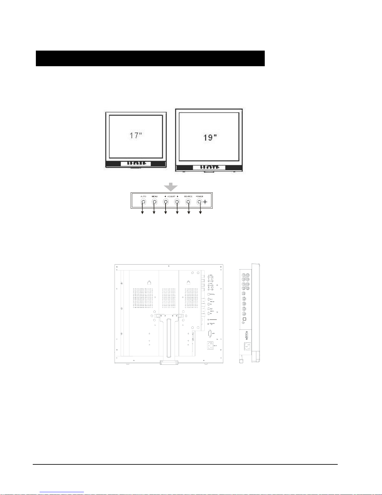
Exploring the Monitor
The monitor is operated by using the buttons on the front panel. The side panels provide the inputs to
connect other equipment to the monitor.
Front Panel
U
O
T
U
M
N
N
W
E
O
D
E
P
U
U
O
S
R
C
E
R
W
O
P
Back Side
6 • XX171-01-00 Rev 1106 VM-617LCD/VM-619LCD Flat Monitors

Backside Connections
1
(R)
2
(L)
5
(R)
(L)
6
9
1, 2AUDIO 2 IN (R, L)
Stereo Audio Signal Input for AV2 or PC
(R)
3
4
(L)
7
(R)
(L)
8
(Refer to Note below)
3, 4 AUDIO 2 OUT (R, L)
Audio looping outputs for AUDIO 2
5, 6 AUDIO 1 IN (R, L))
Stereo Audio Signal Input for AV1 or
S-Video (Refer to Note below)
7, 8 AUDIO 1 OUT (R, L)
10
11
12
13
Audio looping outputs for AUDIO 1
9 S-Video IN
Y/C separated signal input
10 VIDEO 2 OUT
Video looping output for VIDEO 2
14
15
11 VIDEO 2 IN
Composite signal input for VIDEO 2
12 VIDEO 1 OUT
Video looping output for VIDEO 1
16
13. VIDEO 1 IN
Composite signal input for VIDEO 1
17
14. DC OUTPUT
DC 12V / 500mA power output
(For external devices)
15 PC AUDIO IN
16 VGA IN
17.
AC POWER SOCKET
100VAC ~240VAC Input
Note: Audio Connections
Audio 1 Audio 2 PC Audio
PC X
AV1 X
AV2 X
S-Video X
XX171-01-00 Rev 1106 VM-617LCD/VM-619LCD Flat Monitors • 7
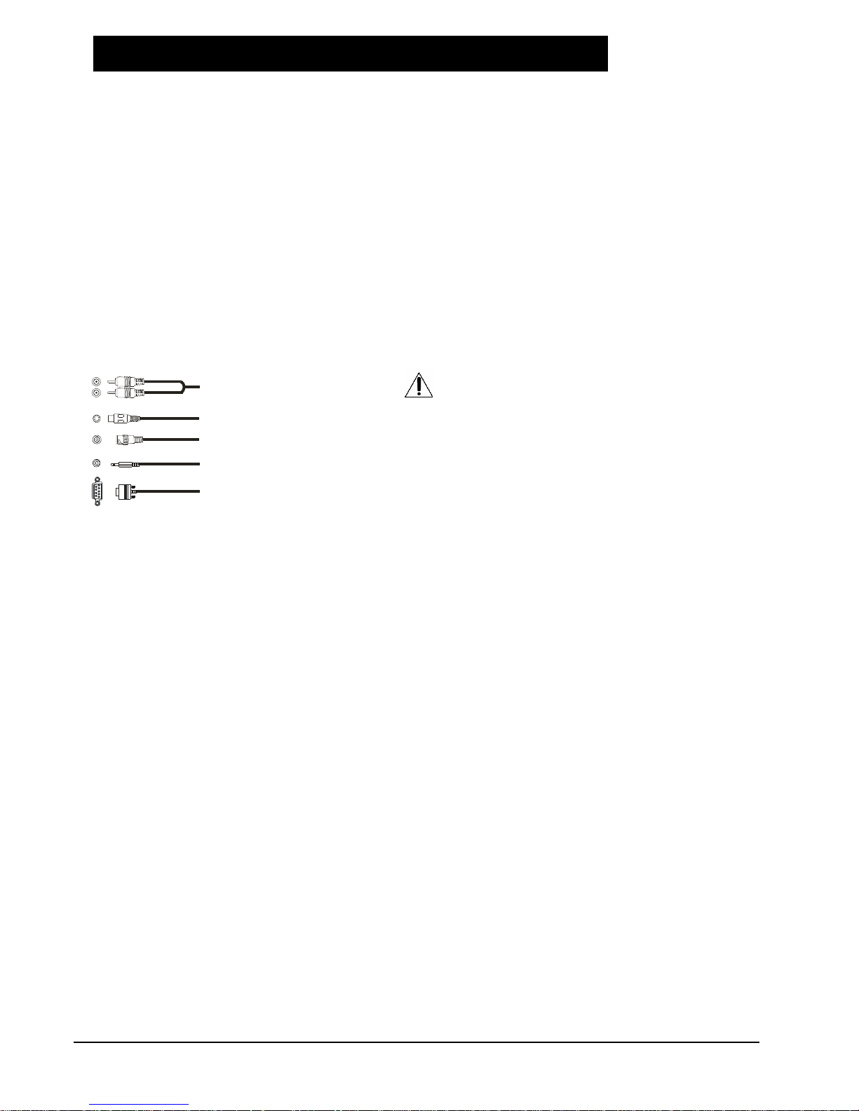
Connecting the Monitor
quip
If you don’t have previous experience with electronic equipment connection, read this section completely
before continuing with the installation.
Note: Cables are not supplied; they are mentioned just for reference.
• Audio cables are usually color coded according to use: red and white for audio. The red audio cable
is for the stereo right channel and the white audio cable is for the stereo left (or mono) channel. The
terminals on the rear panel of the monitor are color coded in the same manner as the cables.
• S-video cables provide better picture performance than standard video cables. S-video cables can
only be used with S-video compatible components.
• BNC cables provide better connection and picture performance.
RCA Audio Cable
S-Video
BNC Connector
NOTE:
To prevent equipment damage,
do not plug in any power cords
until you have finished connecting
all e
ment.
PC Audio Connector
VGA Connector
8 • XX171-01-00 Rev 1106 VM-617LCD/VM-619LCD Flat Monitors
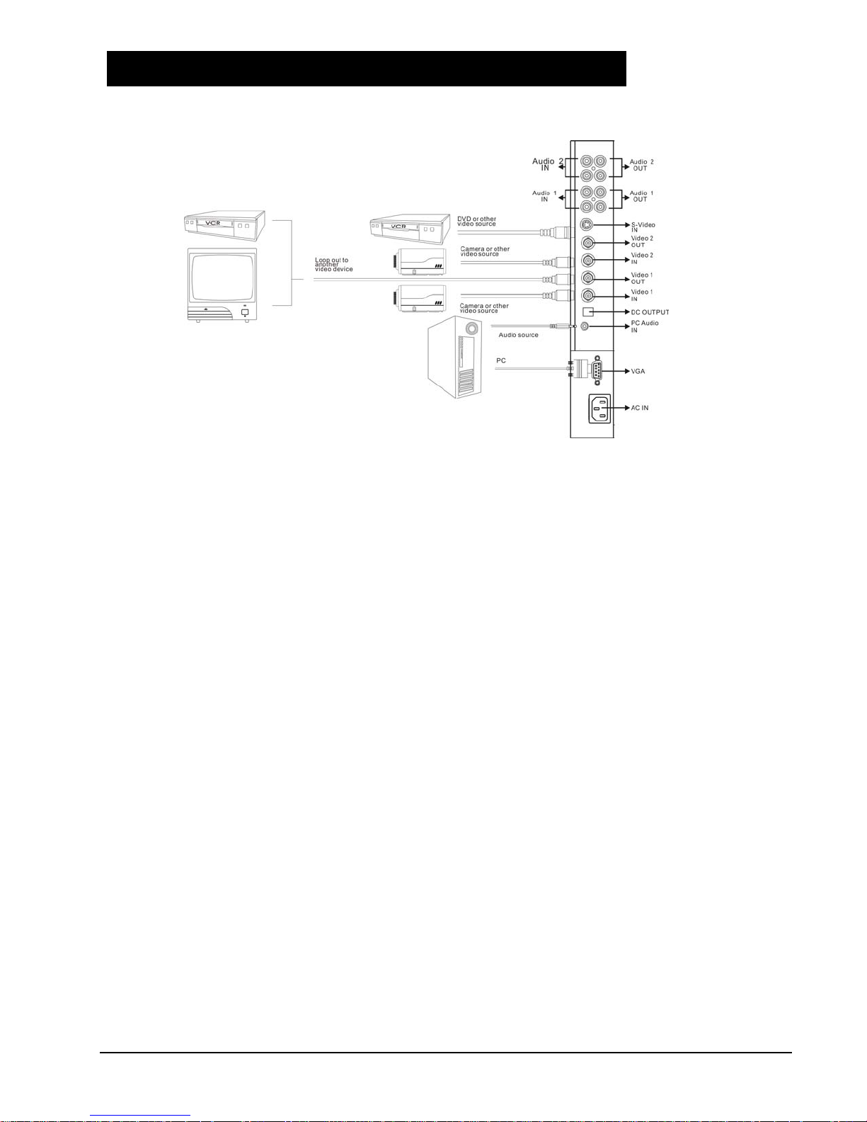
Connecting Devices
1. Connect PC to Monitor through VGA connector as shown on the above picture.
2. Connect external device, such as DVD, to Monitor as shown on the above picture.
3. Connect CCD Camera 1 and 2 to Monitor through Video Input 1 and 2 (BNC connector) as shown on the
above picture.
4. Support resolution.
17” Monitor Display Modes
Mode Resolution Refresh Rate
VGA 640x480 up to 75Hz
SVGA 800x600 up to 75Hz
XGA 1024x768 up to 75Hz
SXGA 1280x1024 up to 75Hz
19” Monitor Display Modes
Mode Resolution Refresh Rate
VGA 640x480 up to 75Hz
SVGA 800x600 up to 75Hz
XGA 1024x768 up to 75Hz
SXGA 1280x1024 up to 75Hz
Although these monitors support above RGB signals, any resolutions not matched by this monitor (SXGA) will
be expanded or shrunk, which will affect image quality.
To view high-quality images, it is recommended that the PC's resolution should be set to SXGA (1280x1024)
resolution.
XX171-01-00 Rev 1106 VM-617LCD/VM-619LCD Flat Monitors • 9

A
Monitor Setup
U
O
T
U
M
AUTO: Auto-optimize displaying picture in PC mode.
Enter: In OSD Menu the “Auto” Button is used for “Enter” function
CCD Mode: Under AV1/AV2 /S-Video press Auto to toggle CCD/Video mode
MENU: OSD menu ON/OFF control; also use to EXIT item
ADJUST: Increase or decrease the value on OSD menu.
Up: Increase value or turn function ON/OFF
Down: Decrease value or turn function ON/OFF
SOURCE: Each press selects input signal from AV1, AV2, S-Video or VGA (PC).
POWER: Monitor power ON/OFF. In OFF mode, monitor will be in standby status.
Green Light: ON mode
Orange Light: Power Saving (refer to note below)
Red Light: OFF mode
Note: 1. AV1, AV2, S-Video: When there is no input signal, LCD monitor
will go into Power Saving mode after 60 seconds.
2. VGA: When there is no input signal, LCD monitor will go into power
saving mode after 5 seconds.
3. PIP: When there is no signal on both input sources, LCD
monitor will go into Power Saving mode after 120 seconds.
N
N
W
E
O
D
E
P
U
R
U
O
S
R
E
C
W
O
P
10 • XX171-01-00 Rev 1106 VM-617LCD/VM-619LCD Flat Monitors

General Setup
Auto Source Detect: The monitor will auto detect the video source when power is turned ON.
OSD Language: English.
Power ON Control: This function is to assign a specific video signal when power ON.
Key Lock: This function is provided to prevent tampering.
To release key lock function press AUTO and DOWN simultaneously.
Power Memorize: This function enables the monitor to memorize the previous power status before
power break.
Channel Display: This function allows the channel title to be displayed on the monitor.
CCD Mode: If video signal source comes directly from CCD camera, use CCD Mode to
obtain better picture performance.
Default: Returns to factory default value.
XX171-01-00 Rev 1106 VM-617LCD/VM-619LCD Flat Monitors • 11

Video Setup
Brightness: Adjusts the overall picture shade and brightness.
Contrast: Permits adjustment of contrast between light and dark areas of the picture.
Color: Adds coloring to the black and white picture content (of a color
signal), and is usually set for viewer’s preference in color saturation.
Tint: Adjusts all the colors on the screen, but is most noticeable to the eye
for reds and yellows, and is usually set for pleasing face tones. (NTSC only.)
Sharpness: Sets the desired sharpening enhancement to the picture.
Color Temperature: Selects color temperature of either 6500°K or 9300°K.
Scale Mode: Selection of picture size.
H-Position: Allows adjustment for horizontal position.
V-Position: Allows adjustment for vertical position.
AGC Control: This function provides a small scale of backlight enhancement to
compensate for insufficient luminance.
Default: Returns to factory default value.
12 • XX171-01-00 Rev 1106 VM-617LCD/VM-619LCD Flat Monitors

VGA Setup
Auto
Brightness
Contr ast
Color Temperature
H-position
V-Pos ition
Clock
Phase
De fau lt
100
9300
No
80
50
50
50
50
No
Auto: Auto detects screen detail data such as clock and phase.
Brightness: Adjusts the overall picture shade and brightness.
Contrast: Permits adjustment of contrast between light and dark areas of the picture.
Color Temperature: Selects color temperature of either 6500°K or 9300°K.
H-position: Allows adjustment for horizontal position.
V-position: Allows adjustment for vertical position.
Clock: Used to adjust best picture quality. It adjusts the numbers of the
pixel clock across one line time. Therefore it can affect the picture
position and size.
Note: Improper adjustment will cause image failure.
Phase: Used to adjust best picture quality. It adjusts the sampling phase across
one pixel time. When the phase is not adjusted properly, the picture will be
unclear. Therefore this value should be carefully adjusted.
Note: Improper adjustment will cause image failure.
Default: Sets monitor to the original factory setting.
XX171-01-00 Rev 1106 VM-617LCD/VM-619LCD Flat Monitors • 13

Audio Setup
Volume: Controls built-in speakers’ output volumes.
Mute: Disables the audio function. To enable, press MUTE again.
Default: Returns audio settings to the original factory setting.
14 • XX171-01-00 Rev 1106 VM-617LCD/VM-619LCD Flat Monitors

PIP Setup
Multi-Mode: Allows the PIP mode to be selected.
Sub Source: Allows the PIP Sub source to be selected.
Sub Window Size: Selects size of PIP window.
Sub Window H-Position: Controls the PIP window horizontal position.
Sub Window V-Position: Controls the PIP window vertical position.
Switching: Enables switching PIP sources.
Switching Time: Controls PIP source switching time.
Audio Source: Selects PIP mode audio source.
Note: PIP hot key: Auto + Menu
XX171-01-00 Rev 1106 VM-617LCD/VM-619LCD Flat Monitors • 15
Rack M
5
SA S
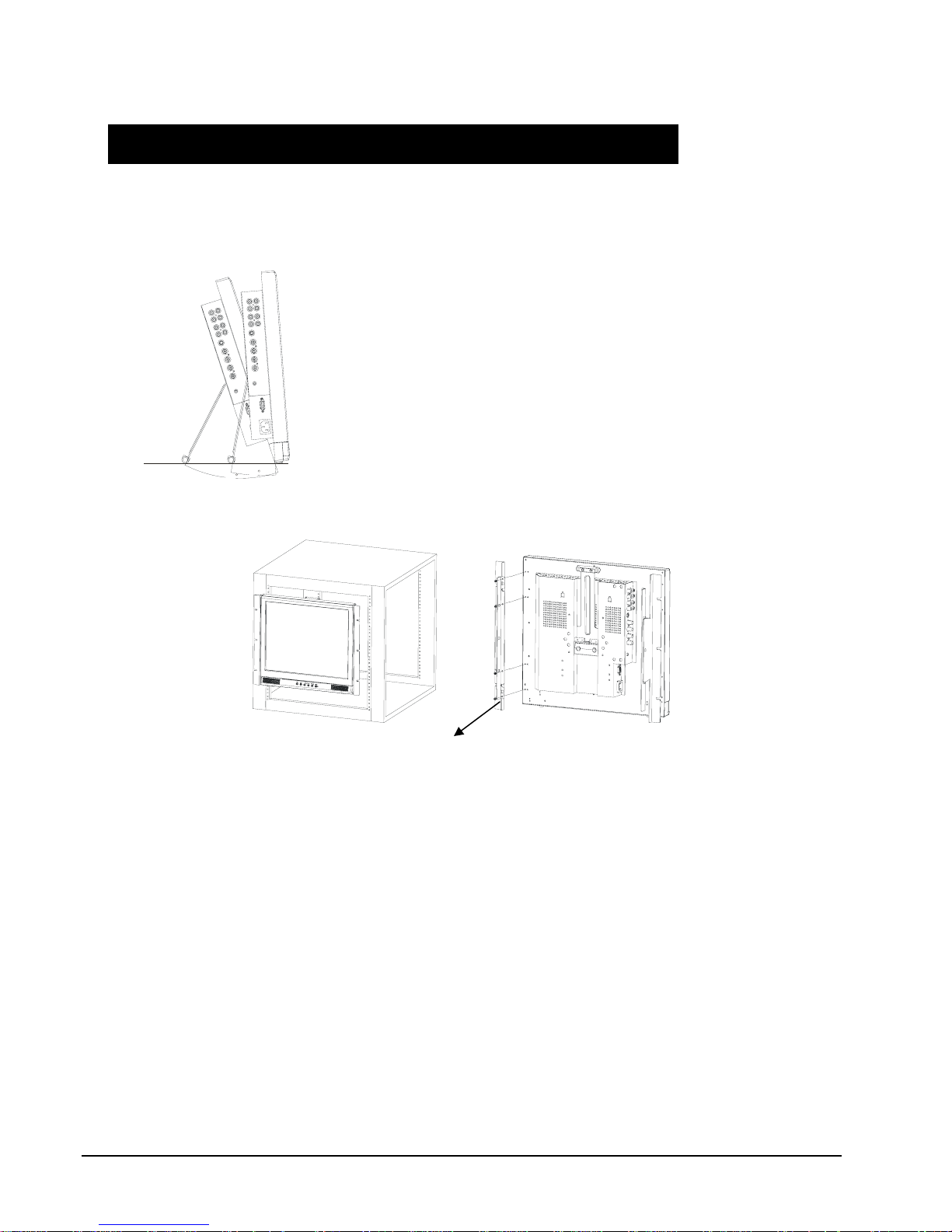
LCD Monitor Mounting Guide
Desktop Arm Mount (VESA Standard)
Adjust the viewing angle of LCD monitor to fit most
comfortable monitoring status.
15
15
45
4
Mounting the monitor on the rack
When adjusting the VE
tandard
Arms to the back side of the LCD
monitor, use the 4x8 (mm) screw.
For further information, refer to the
Arm Manual.
Note:
When adjusting to a rack, an optional rack mount is needed for the back side of the LCD monitor.
ount
16 • XX171-01-00 Rev 1106 VM-617LCD/VM-619LCD Flat Monitors

Troubleshooting
Before calling a service technician, check the following table for a possible cause of the problem and a solution.
Symptom Solution
Monitor will not turn on ● Make sure the power cord is plugged in, then press POWER button.
No picture, no sound ● Check cable connections. There is no sound in “Video Loss”.
No sound, picture OK ● Check audio cable connections.
● Try pressing Volume Up button in the Menu.
Poor color, sound OK ● Check cable connections.
● Adjust Video set up menu.
Poor color or no color ● Adjust Color and/or Tint (NTSC only).
XX171-01-00 Rev 1106 VM-617LCD/VM-619LCD Flat Monitors • 17

LCD Color Monitor Specification
(∗1) The brightness spec. is from panel spec.
(∗2) It is not guaranteed for all the specified range.
Design and Specifications are subject to change without notice.
Model Number VM-617LCD VM-619LCD
Panel Size 17.0” 19.0”
Aspect Ratio 5:4 5:4
Resolution/Scan
Brightness 300cd/m2 (*1) 270cd/m2 (∗1)
Viewing Angle (H/V)
Response Time 8ms (Typ) 8ms (Typ)
Sync. Format NTSC/PAL
Frequency (Horizontal) PC: 31.5K - 80KHz, Video 15750 / 15625Hz (NTSC/PAL) (∗2)
Frequency (Vertical) PC: 56Hz -75Hz, Video: 50 / 60Hz (∗2)
Input
Interfaces
Built-in Speakers Yes (2 pcs)
Front Panel Button Power, Source, Up/Down, Menu, Auto
OSD Language English
VESA Mounting VESA 100
Weight 12.3 lb (5.6 kg) 13.9 lb (6.3 kg)
External Dimensions
(WxHxD)
Safety & EMI UL, CUL, FCC/B, CE
Power 100-240 VAC, 50/60Hz
Power Consumption (max) 40 W 45 W
Temp (Oper.) 14°F ~122°F (-10°C to 50°C)
Humidity 20% ~ 80%
Accessories Power Cord, User Manual
Video
Interface
Audio
Interface
Input Power AC In x 1
Termination 75 ohm (Auto Termination)
640 x 480
@ 60/72/75
800 x 600
@ 56/60/72/75
1024 x 768
@ 60/70/75
1280 x 1024
@ 60/75
Left 85°/Right 85°
Up 85°/Down 85°
D-SUB 15IN x 1, Video In x 2 (BNC), Video Out x 2 (BNC),
Audio In x 2, Audio Out x 2, PC-Audio In x 1
15.4x13.9x2.9 in.
(390x354.5x74.2 mm)
640 x 480
@ 60/72/75
800 x 600
@ 56/60/72/75
1024 x 768
@ 60/70/75
1280 x 1024
@ 60/75
Left 80°/Right 80°
Up 75°/Down 60°
S-Video In x 1
16.7x15.6x3.0 in.
(425x396x75.6 mm)
18 • XX171-01-00 Rev 1106 VM-617LCD/VM-619LCD Flat Monitors

LCD Color Monitor Dimensions
XX171-01-00 Rev 1106 VM-617LCD/VM-619LCD Flat Monitors • 19

Maintenance
The VM-617LCD and VM-619LCD monitors require no scheduled maintenance.
Shipping Instructions
Use the following procedure when returning a unit to the factory:
1. Call or write Vicon for a Return Authorization (R.A.) at one of the locations listed below. Record the name
of the Vicon employee who issued the R.A.
Vicon Industries Inc.
89 Arkay Drive
Hauppauge, NY 11788
Phone: 631-952-CCTV (2288); Toll-Free: 1-800-645-9116; Fax: 631-951-CCTV (2288)
For service or returns from countries in Europe, contact:
Vicon Industries Ltd
Brunel Way
Fareham, PO15 5TX
United Kingdom
Phone: +44 (0) 1489/566300; Fax: +44 (0) 1489/566322
2. Attach a sheet of paper to the unit with the following information:
a. Name and address of the company returning the unit
b. Name of the Vicon employee who issued the R.A.
c. R. A. number
d. Brief description of the installation
e. Complete description of the problem and circumstances under which it occurs
f. Unit’s original date of purchase, if still under warranty
3. Pack the unit carefully. Use the original shipping carton or its equivalent for maximum protection.
4. Mark the R.A. number on the outside of the carton on the shipping label.
20 • XX171-01-00 Rev 1106 VM-617LCD/VM-619LCD Flat Monitors

Vicon Standard Equipment Warranty
Vicon Industries Inc. (the “Company”) warrants your equipment to be free from defects in material and workmanship under
Normal Use from the date of original retail purchase for a period of three years, with the following exceptions:
1. VCRs, all models: Labor and video heads warranted for 120 days from date of original retail purchase. All other
2. Video monitor CRT (cathode ray tube) and LCD monitors, all models: One year from date of original retail
3. Uninterruptible Power Supplies: Two years from date of original retail purchase.
4. VDR-204 and VDR-208 Recorder Series: One year from date of original retail purchase.
5. Normal Use excludes prolonged use of lens and pan-and-tilt motors, gear heads, and gears due to continuous
Date of retail purchase is the date original end-user takes possession of the equipment, or, at the sole discretion of the
Company, the date the equipment first becomes operational by the original end-user.
The sole remedy under this Warranty is that defective equipment be repaired or (at the Company’s option) replaced, at
Company repair centers, provided the equipment has been authorized for return by the Company, and the return shipment
is prepaid in accordance with policy.
The Company will not be obligated to repair or replace equipment showing abuse or damage, or to parts which in the
judgment of the Company are not defective, or any equipment which may have been tampered with, altered, misused, or
been subject to unauthorized repair.
Software supplied either separately or in hardw are is furnished on an “As Is” basis. Vicon does not warrant that
such software shall be error (bug) free. Software support via telephone, if provided at no cost, may be
discontinued at any time without notice at Vicon’s sole discretion. Vicon reserves the right to make changes to
its software in any of its products at any time and without notice.
This Warranty is in lieu of all other conditions and warranties express or implied as to the Goods, including any
warranty of merchantability or fitness and the remedy specified in this Warranty is in lieu of all other remedies
available to the Purchaser.
No one is authorized to assume any liability on behalf of the Company, or impose any obligations on it in connection with
the sale of any Goods, other than that which is specified above. In no event will the Company be liable for indirect, special,
incidental, consequential, or other damages, whether arising from interrupted equipment operation, loss of data,
replacement of equipment or software, costs or repairs undertaken by the Purchaser, or other causes.
This warranty applies to all sales made by the Company or its dealers and shall be governed by the laws of New York
State without regard to its conflict of laws principles. This Warranty shall be enforceable against the Company only in the
courts located in the State of New York.
The form of this Warranty is effective August 2, 2006.
THE TERMS OF THIS WARRANTY APPLY ONLY TO SALES MADE WHILE THIS WARRANTY IS IN EFFECT. THIS
WARRANTY SHALL BE OF NO EFFECT IF AT THE TIME OF SALE A DIFFERENT WARRANTY IS POSTED ON THE
COMPANY’S WEBSITE, WWW.VICON-CCTV.COM. IN THAT EVENT, THE TERMS OF THE POSTED WARRANTY
SHALL APPLY EXCLUSIVELY.
parts warranted for one year from date of original retail purchase.
purchase.
use of “autopan” or “tour” modes of operation. Such continuous operation is outside the scope of this warranty.
Vicon Part Number: 8006-9010-03-02 Rev 806
XX171-01-00 Rev 1106 VM-617LCD/VM-619LCD Flat Monitors • 21

Vicon Industries Inc.
Corporate Headquarters
89 Arkay Drive
Hauppauge, New York 11788
631-952-CCTV (2288) 800-645-9116
Fax: 631-951-CCTV (2288)
Vicon Europe
Headquarters
Brunel Way
Fareham, PO15 5TX
United Kingdom
+44 (0) 1489 566300
Fax: +44 (0) 1489 566322
Brussels Office
Planet II - Unit E
Leuvensesteenweg 542
B-1930 Zaventem
Belgium
+32 (2) 712 8780
Fax: +32 (2) 712 8781
Far East Office
Unit 5, 17/F, Metropole Square
8 On Yiu Street, Shatin
New Territories,
Hong Kong
(852) 2145-7118
Fax: (852) 2145-7117
Internet Address: www.vicon-cctv.com
 Loading...