

Page 1
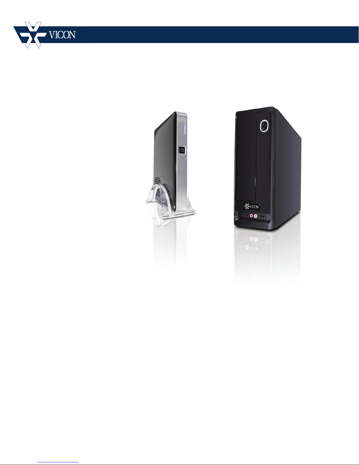
Quick Guide
XX255-21-00
Tel: 631-952-2288 Fax: 631-951-2288 Toll Free: 800-645-9116
24-Hour Technical Support: 800-34-VICON (800-348-4266) UK: 44/(0) 1489-566300
Vicon Industries Inc. does not warrant that the functions contained in this equipment will meet your requirements or that the
operation will be entirely error free or perform precisely as described in the documentation. This system has not been designed
to be used in life-critical situations and must not be used for this purpose.
Document Number: 8009-8255-21-00
Product specications subject to change without notice.
ViconNet JUMP and ZONE
Vicon Industries Inc.
www.vicon-security.com
Issued: 714
Copyright © 2014 Vicon Industries Inc. All rights reserved.
Page 2
Important Safeguards – I ndoor Use
GRAPHIC SYMBOL EXPLANATION
The lightning bolt symbol alerts the user to the presence of
dangerous voltage that may present the risk of electric shock.
The exclamation point symbol alerts the user to the presence of
important operating and maintenance instructions.
WARNING
To reduce a risk of fire or electric shock, do not
expose this product to rain or moisture.
1. Read Instructions - Read all safety and operating instructions
before the product is operated.
2. Retain Instructions - Retain all safety and operating
instructions for future reference.
3. Heed Warnings - Pay attention to all product warnings.
4. Follow Instructions - Follow all operating instructions.
5. Installation and Wiring - The equipment shall be installed and
wired in accordance with the National Electrical Code,
ANSI/NFPA 70.
6. Cleaning - (Do not use caustic, abrasive or aerosol
cleaners)
a) For units that CAN BE DISCONNECTED from the power
source, use a damp cloth for cleaning.
units that CANNOT BE DISCONNECTED from the
b) For
power source, use a damp cloth for cleaning and do not
allow moisture or liquids to enter vents.
7. Attachments - Use only UL Listed Vicon recommended
attachments to prevent unit damage and personal injury.
8. Water and Moisture - Use only product s designed f or outdoor
environments where they will be exposed to water or moisture.
9. Accessories - Do not place the unit on an unstable surface to
avoid falling. Use only UL Listed Vicon recommended mounting
accessories.
10. Ventilation - Do not block ventilating slots and openings as
they ensure reliable operation. Do not place the unit near a heat
source or into an enclosure unless recommended by Vicon.
11. Grounding - Only products equipped with a 3-prong
grounded plug should be inserted into a grounded power outlet.
Contact an electrician to replace an obsolete outlet. Do not force
a plug into a non-grounded outlet.
12. Power Cord Protection - Power supply cords should not be
routed in trafficked areas or in tight spaces where they will be
pinched or used to bear weight. Allow some slack in the cord
where it enters the unit.
13. Lightning - Disconnect the product from its power source and
cable system when possible to prevent damage due to lightning
and power-line surges.
14. Power Lines - Do not locate outside cables over power or
utility lines where they can fall and make direct contact. Contact
with power lines can be fatal.
15. Overloading - Do not overload wall outlets and extension
cords to prevent risk of fire and electric shock.
16. Object and Liquid Entry - Never probe through, or spill liquid
into, enclosure openings to prevent risk of fire or electric shock.
17. Servicing - Refer all servicing to qualified service personnel.
18. Damage Requiring Service - Obtain service when:
a) The power-supply cord or plug is damaged.
b) Objects have fallen or liquid has been spilled into the
product.
c) The product is not designed for outdoor use and has been
exposed to water or moisture.
d) The product does not operate per the operating instructions.
Perform Vicon recommended adjustments, modifications
and troubleshooting only to avoid unit damage and personal
injury.
e) The product has been dropped.
f) The product shows a significant change in performance.
19. Replacement Parts - Use only Vicon specified replacement
parts or an approved equivalent to prevent unit damage and injury.
20. Safety Check - Request safety checks to be performed
following repair or maintenance to verify proper operation.
21. ESD Precaution - Take all normal electrostatic disc harge
precautions to avoid component damage during installation and
operation.
22. For 230 VAC Devices Only - When the disconnect device is
not incorporated in the equipment or when the plug on the power
supply is intended to serve as the disconnect device, follow the
guidelines below:
a) For permanently connected 230 VAC units, a readily
accessible disconnect device must be incorporated int o the
site wiring.
b) For 230 VAC units with a plug, the outlet must be installed
near the unit and be easily accessible.
23. For Devices Requiring a Separate Power Supply – All
devices requiring a separate power supply shall be powered by a
UL Listed, Class 2 Power Supply.
24. Lithium Batteries Only:
Fire and burn hazard. Do not recharge, disassemble,
heat above 212°F or incinerate. Keep battery out of
reach of children and in original package until ready
to use. Dispose of used batteries promptly.
Risk of explosion if battery is replaced by incorrect
type. Dispose of used batteries according to the
instructions.
WARNING
Page 3

Important Safeguards – I ndoor Use (Con t )
25. For Rack-Mounted U nits Only – The following precautions apply
to all rack-mounted units.
a) Elevated Operating Ambient - If installed in a closed or multi-unit
rack assembly, the operating ambient temperature of the rack
environment may be greater than room ambient. Therefore,
consideration should be given to installing the equipment in an
environment compatible with the m aximum ambient temperature
(Tma) specified by the manufacturer.
b) Reduced Air Flow - Installation of the equipment in a rack should
be such that the amount of air flow required for safe operation of
the equipment is not compromised.
c) Mechanical Loading - Mounting of the equipment in the rack
should be such that a hazardous condition is not achieved due to
uneven mechanical loading.
d) Circuit Overloading - Consideration should be given to the
connection of the equipment to the supply circuit and the effect
that overloading of the circuits might have on overcurrent
protection and supply wiring. Appropriate consideration of
equipment nameplate ratings should be used when addressing
this concern.
e) Reliable Earthing - Reliable earthing of rack-mounted equipment
should be maintained. Particular attention should be given to
supply connections other than direct connections to the branch
circuit (e.g. use of power strips).
Page 4

Quick Guide | 3
V
Quick Guide
iconNet JUMP/ZONE NVR
This manual provides a quick ov er view for the configuration and operation
of the ViconNet JUMP and ZONE NVRs.
ViconNet JUMP and ZONE offer all the performance and features of the
open platform enterprise-scale software, limited to a s ing le NVR system,
JUMP supporting up to 6 cameras and ZONE suppor t ing up t o 16 or 24
cameras. It is available as soft w ar e only, downloaded from Vicon’ s
website, or preloaded on an NVR.
ViconNet software provides outstanding functionality and an intuitive
interface for administrators, security managers and system operators
anywhere on the network. Vico nNet JUMP and ZONE eas ily integrates
with third party access co nt r ol software. They can be used in conjunction
with Vicon’s Virtual Matrix Display Controller (VMDC ) and are compatible
with other workstations an d NV R s .
The VN-NVR-JUMP (hardware sold by Vicon) is not intended for local
display. It can be used with t he free VN-VIEWER/ViconNet Web Viewer or
a Workstation to view local video (refer to Using the Web Viewer at the
end of this manual). The VN-NVR-ZONE NVR series is available with
various options for storage in des k-top or r ack-mount versions.
Page 5
4 | Quick Guide
Connecting the NVRs
Note
Ports may vary subject to v ar iat ions in hardware, but will be similar in
function.
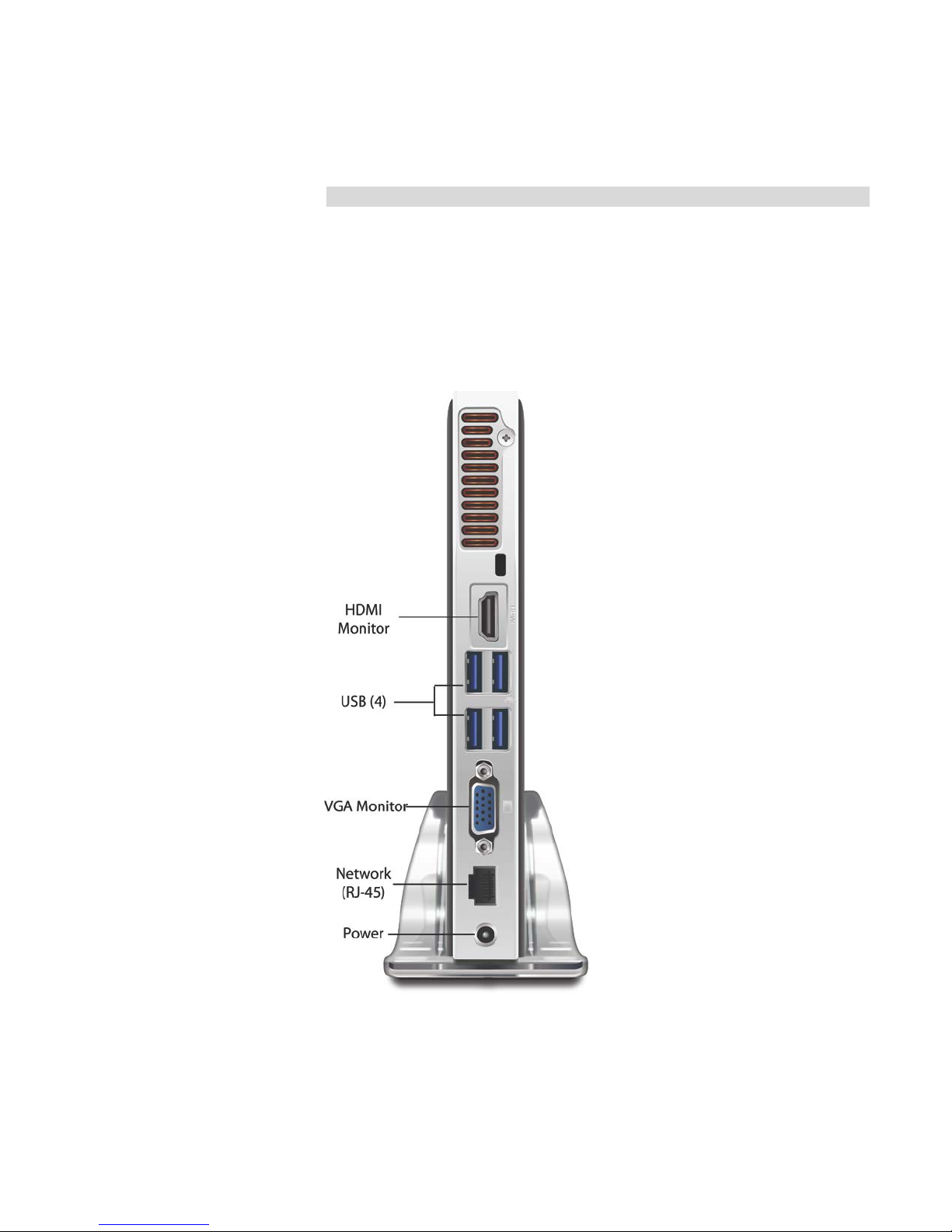
Rear Panel Connections – ViconNet JUMP NVR
Refer to the figure below for a des cr i pt ion of the rear panel connecti ons for
the ViconNet JUMP N VR (VJ P).
• HDMI : Connect to a monitor with a HDMI conn ection.
• VGA: Connect to a monitor with a VGA connection.
Page 6

• USB Por ts (4): Used to connect to USB devices such as a
• Network Port: A standard RJ-45 connector used to connect to
• Power R ec eptacle: Jack for 19 VDC power supply provided.
Side Panel
• eSATA Port (1): Used to connect to an external SATA device.
• Headphones Out, Mic In Jacks: Used to connect audio devices
• Me mory Card slot:
Quick Guide | 5
Note that on this specific hardw ar e configuration both display
ports can be used for the purpose of setting up the NVR and
camera but are not designed t o be used for continuous video
viewing (use ViconNet Vie w er from a remote PC).
mouse, keyboard, printer, flas h drive, etc.
a LAN/WAN.
and microphones.
Page 7
6 | Quick Guide
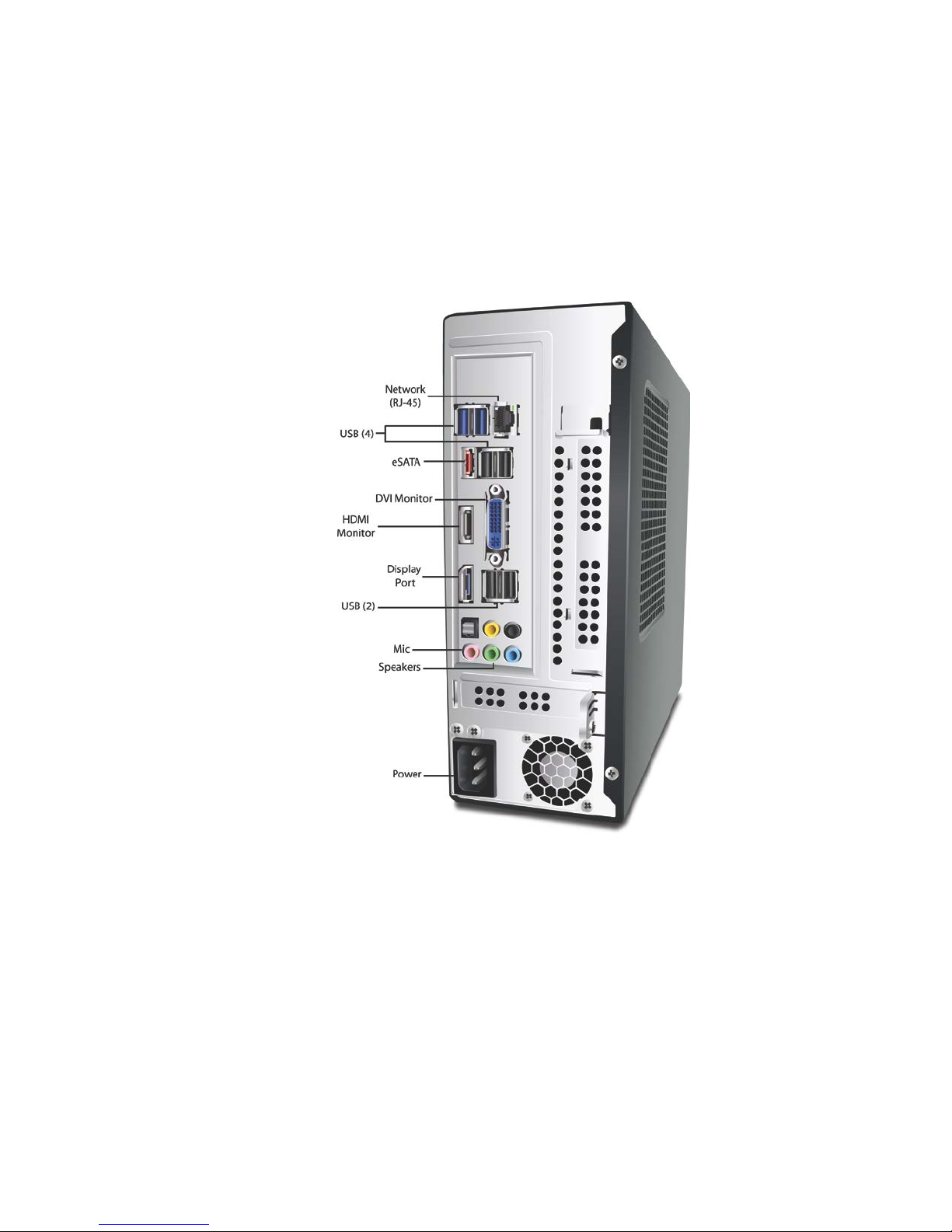
Rear Panel Connections - ViconNet ZONE NVR Series
The ViconNet ZONE NVR (VZN) is available in desk-top or rack-mount
versions. The connections are similar for both. The illustrati on below
shows the desk-top versio n.
• Network Port: A standard RJ-45 connector used to connect to
a LAN/WAN.
• USB Por ts (6): Used to connect to USB dev ices such as a
mouse, keyboard, printer, flas h drive, etc.
• eSAT A Port (1): Used to connect to an external SATA device.
• DVI: C onnect to a monitor with a DVI connection.
• HDMI : Connect to a monitor with a HDMI conn ection.
• Disp lay Port: Used to connect a video so ur ce t o a display
source.
Page 8

Mounting
Quick Guide | 7
• Speaker Out, Mic In Jacks: Used to connec t audio devices and
microphones.
• Power R ec eptacle: Used to connect the provided power cable.
Front
• USB Port (2): Used to connect to USB devic es s uch as a
mouse, keyboard, printer, flash drive, etc.
• Speaker Out, Mic In Jacks: Used to con nec t audio devices and
microphones.
The ViconNet JUM P NV R c an be desk-top mounted in a stand provi ded or
VESA mounted. The ViconNet ZONE NVR is available in desk-top or rackmount versions.
Desktop
The NVR can rest on a clean and dry flat service; the JUMP version can
be placed in the stand provided. The desk or table must pr ovide a surface
of suitable strength to sup por t t he weight of the NVR. In addition, there
must be enough area left ar ound the unit to provide suitable airflow for
cooling.
Warning
Failure to leave space for cool in g m ay result in malfunctioning an d
possible failure of the NVR.
VESA
A VESA bracket is provided to m ount the VN-NVR-JUMP to a monitor.
Rack
The VZN -RK models were designed to be mounted in a st andard 19-inch
(483 mm) wide vertical ra ck.
It is recommended that at least 1 RU of space [1.75 in. (44.45 mm)] be l eft
in between multiple units mounted in the same rack for cooling purposes.
Warning
Failure to leave space for cool ing between recorders may result in
malfunctioning and poss ib le f ai lure of the recorder
Page 9

8 | Quick Guide
ViconNet JUMP/ZONE NVR Connections
After the ViconNet JUMP/ZONE NVR is permanently mounted, the
connections are made. Refer to Rear Panel diagram s as needed.
Important Notes
• The connection of external hardware may require simple hand
tools. Do not apply power or plug-in the unit to any outlet until
instructed to do so.
• Disab le t he AC power to prevent installer injury and damage to the
unit.
• Before beginning the hardware installation, ensure that the
following environmental conditions have been met:
• The sur face on which the NVR hardware is to be placed must
be level.
• The roo m or ar ea designated for the NVR hardware installation
must be well ventilated.
Page 10

Quick Guide | 9
Make the following conn ections to the NVR:
Note
A mouse and keyboard are r equired for setup.
• Posit io n t he monitor(s) in a permanent fixed location. Connect the
monitor to the appropriate connector, VGA, DVI or HDMI (a DVIVGA adapter can be used if requ ired).
• Inser t one si de of a standard LAN cable to the Network Port’s RJ-
45 connector. Insert the other RJ-45 connector into the LAN s ide
of the network.
• Inser t t he connector of the provided power supply into the
NVR’s power receptacle. Do not connect the remaining end to a
power receptacle until inst r ucted.
• Connect t he monitor(s) to the power sourc e and switch on.
To ensure that the NVR is protected dur ing a power failure and that no
important data is lost, it must be connected to an uninterrupt ibl e pow er
source (UPS) before use.
• Connect t he NVR's power supply to the UPS pow er r eceptacle.
• Connect t he UPS power cord to the wall outlet.
• Power on t he UPS and ensure that it is wor king properly.
• Power on t he NVR.
Page 11
10 | Quick Guide
Using ViconNet
Adding Cameras and Devices
A camera or device must be added to the Nucleus of the system to be
recognized on the ViconN et site list. ViconNet cameras must point to the
Nucleus in their setup. Vicon open standard cameras, as well as cameras
from other manufacturer s ( t hird par t y), must be added to the system.
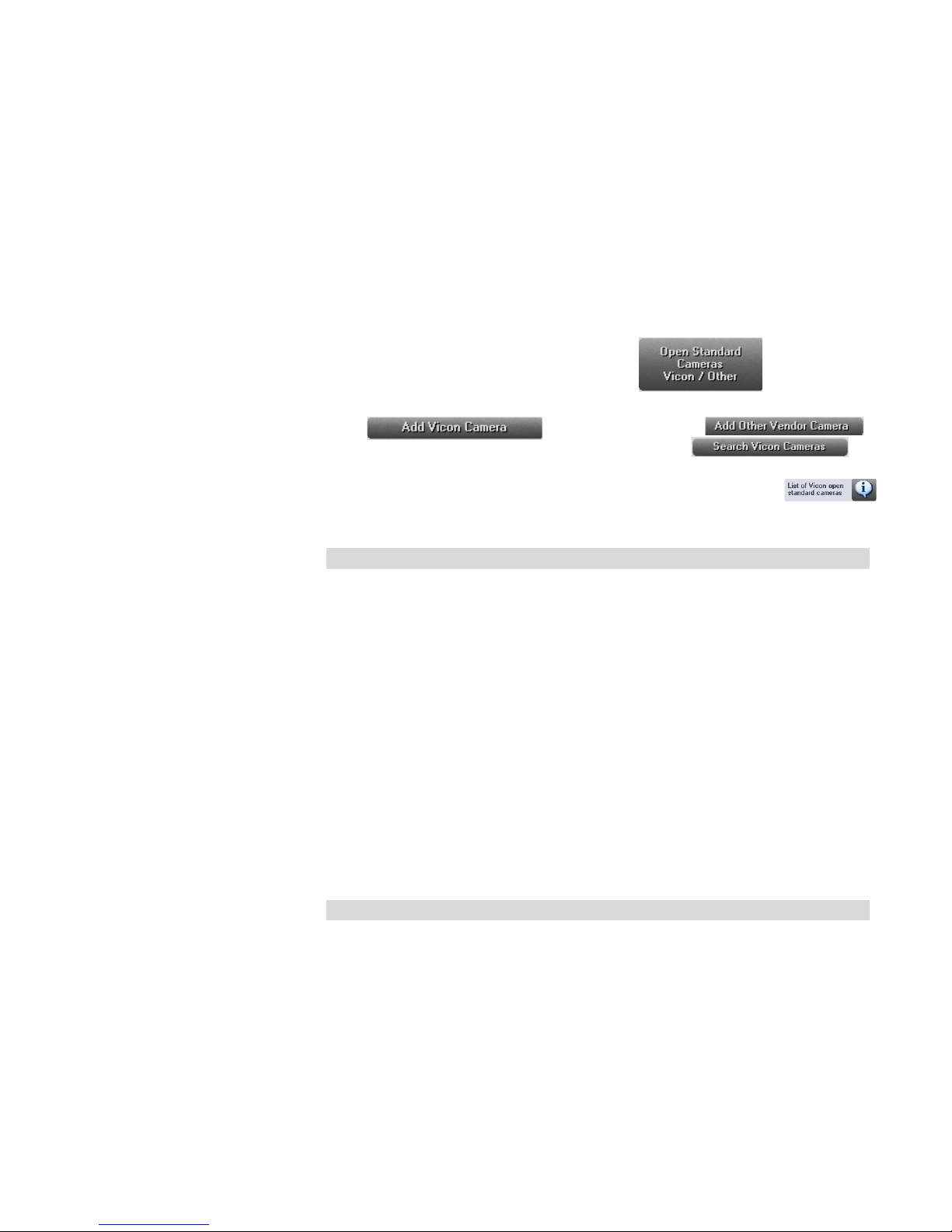
From the System Settings window, select . The Vicon
and other vendor open standard camera settings scr een displays.
Click for a Vicon camera or .
for open standard cameras from other vendors, or
for Vicon cameras already setup on the Open Standard Camera settings
screen. If you are not sure what type of camera you have, clic k
to access a list of Vicon camer as supported as open standard. The
detected cameras are displayed and added automatically to the list.
Getting Started
Note
The JUMP and ZONE systems h ave limitations to the number o f cameras
that can be displayed in the Site List, 6 for the JUMP and 16 or 24 for t he
ZONE. Cameras are added to the Site List in the order they ar e connected
to the system. For example, for a JUMP, the first 6 cameras sele ct ed will
be listed in the Site List, no matter how many cameras are added
afterwards. Therefore, it i s important to make your camer a selections
carefully in order to have acces s t o those you require.
After all connections are ma de, the NVR can be configured. The NVRs are
delivered registered fro m the factory and the storage database is
configured to the maximum. Working with ViconNet is the same for the
NVR or for an NVR that is loaded wit h VJP-SWV7 or the VZN-SWV7.
Note
The VJP NVR does not support local display. It can be used with the
ViconNet Web Viewer to view local video (refer to Using the Web Viewer
at the end of this manual).
Login
Logging in to the ViconNet application is performed using your assigned
user name and password. The al lowed system operations are dependent
on your assigned authoriz ation rights.
Page 12
Quick Guide | 11
To log in to the ViconNet application:
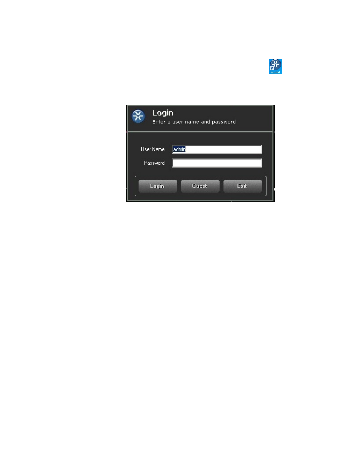
1. At your NVR, double-click the Vicon Net icon on your
Windows® desktop or select Start
ViconNet. The ViconNet
Login window appears. E nt er your user name and password; the
default login in is admin and no password.
1. Click Login; the Main screen displays.
Page 13
12 | Quick Guide
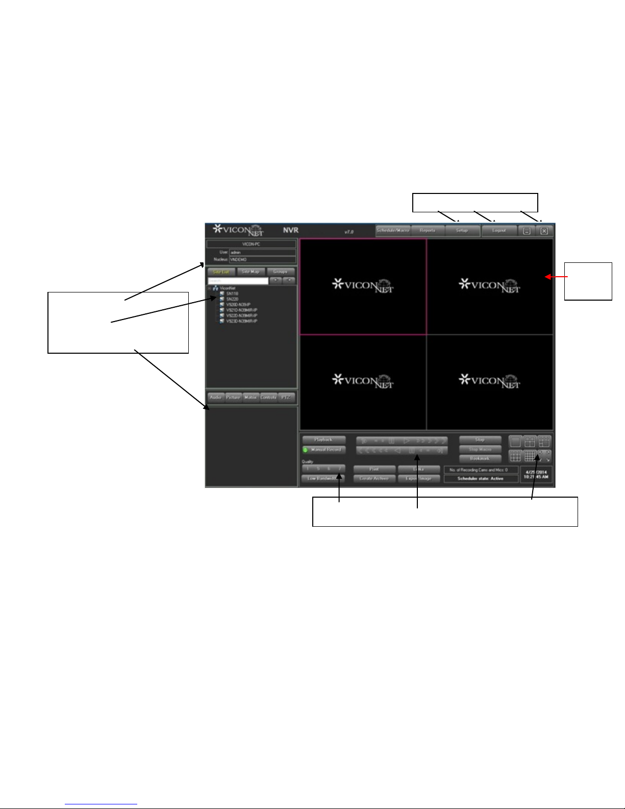
Setup Logout Exit
Current Details
Control Display Area
Function Playback Display
Controls Controls Mode Controls
Video
Main Window
After logging in to the ViconNet application, the Main window is displayed,
as shown below, enabling you to:
• View and l ist en t o l ive video and audio.
• Play back recorded video and audio.
• Print or export image frames.
Site List
The window shown above provides access to all the basic fun ct ionality
required to operate the sy st em.
Display
Page 14
Configuring Storage Database Utilities
The ViconNet system ena bles you to configure the storage loc at i ons of the
video and audio database in your system, depending on your
requirements. The NV R's storage database is preconfigured at the factory
to the maximum allowed. If you are using the VN-SW-JUMP or VN-SWZONE software on your own NVR, the storage database shou ld be
configured.
When you run the ViconNet application for the first time, the d efault
storage location settings a r e appl icable. Each storage location can be
made up of a combination of mult iple disks (sections), depending on the
number of available disks in the system.
Configuring Storage Locations (typically not required for hardware
sold by Vicon)
Configuring a storage loca t ion consists of defining the actua l location of
the video/audio database. You must also define the storage size of each
storage location, depending on the available disk siz e.
Quick Guide | 13
This function is disabled while recording (manual, aut omatic, or macroinitiated) is in progress.
To configure Storage Database Utilities:
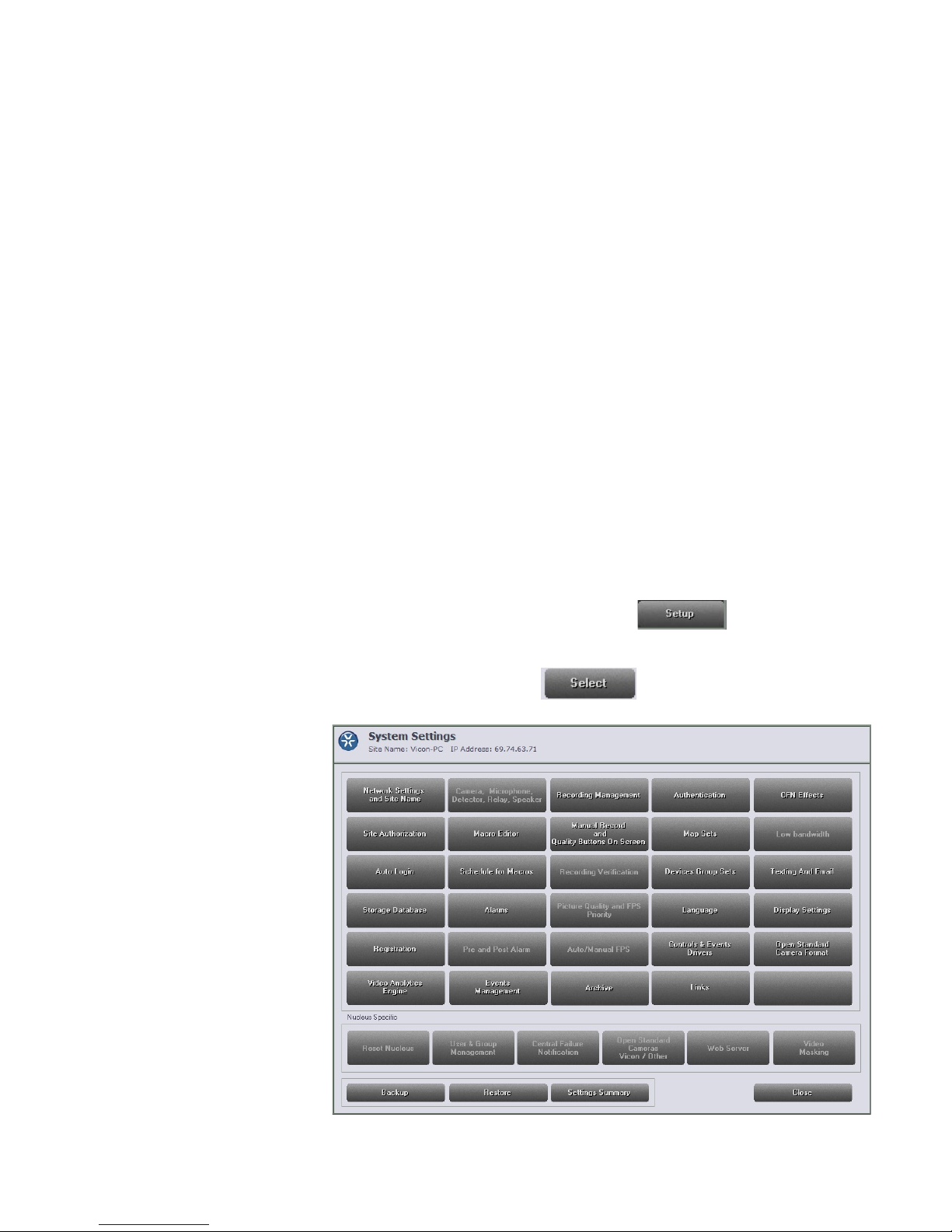
1. From the ViconNet Main window, click . The Setup Site
Selection window is displayed, showing a list of all current ly connected
transmitters and Workstations.
2. Select your unit and click . The System Settings window
is displayed.
Page 15
14 | Quick Guide
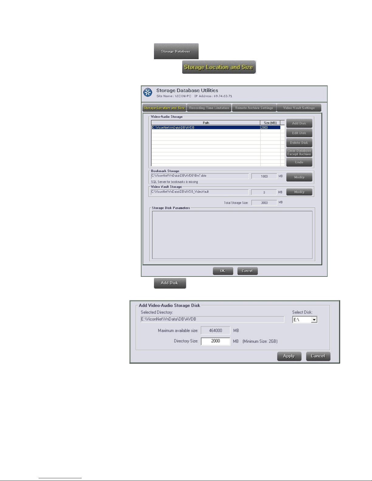
3. Click . The Storage Database Utilities window is
displayed with the tab selected by default.
4. Click . The bottom portion of the Storage Database
Utilities window is enabled, as follows:
5. Click the arrow next to the Select Disk dropdown list and then select
the required location. Do not rec or d on t he OS C drive or any other
internal drive if a RAID is att ac hed.
The system automatical ly detects the Maximum Size of the selected
directory, depending on th e available disk space. The def ault directory
size is 2000 MB (which is also the m inimum size).
Page 16
Navigator Window
Quick Guide | 15
6. In the Directory Size field, type in the required size (between the
minimum and maximum).
7. Click in the bottom of the window. The new st or age location
information is added to the st or age l ocation list at the top of the window.
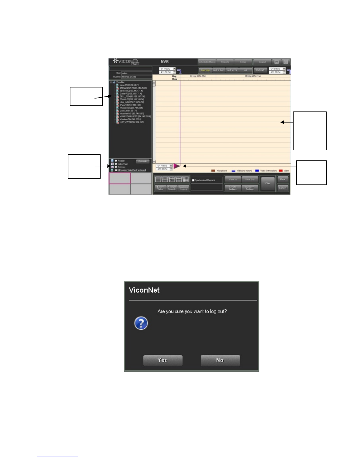
Click on the Main window to display the Navigator
window, which displays a visual mapping of the storage location, enabling
you to:
• Select and playback (in the Main window ) recor ded video and audio
segments.
• Select t he pl ayback start time and time interval.
• Create or r emove archives of recorded video and audio segments.
• Link re lated audio and video and synchronize multiple playbac k
segments.
• Searc h for unique recorded segments.
• Create video files.
The following example illustrates the elements and optio ns in the
Navigator window, w hich provide access to all playbac k functionality:
Page 17
16 | Quick Guide
Playback
Navigator
Navigator
Recorded
List
List
Controls
Logout and Exit
Device
Content
Area
Start
Time
Logging Out
Logging out is performed w hen you want to exit from the ViconNet
application, but need the application to remain open, for exa m ple, to log in
as a different user.
To log out of the ViconNet application:
1. Click Logout in the Main window toolbar. The f ol lowing message is
displayed:
2. Click Yes.
Page 18

Quick Guide | 17
Exiting
Exiting is performed when you want to exit the ViconNet appl icat i on.
To close ViconNet and exit to the operating system:
Either:
• Click the Setup button at the top of the M ain screen to display the
Setup Site Selection window and c l ick the Exit to O.S. button.
OR
• Click the X button on the Main window toolbar. In the confirmation
window displayed, click Yes to exit ( close) the application.
OR
Click Logout at t he top of the Main Window Toolbar to disp lay t he Login
window and click Exit.
Viewing and Listening to Video
Step 1: Selecting the Display Mode
Selecting the display mode enables you to determine the maximum
number of video display locations for viewing and listening to live
video and audio at one time in the Video Display area of the Main
window. The VJP NVR supports up to 6 cameras. The VZN NVRs
support up to 16 or 24 cameras, m odel dependant.
Note
The ViconNet JUMP does not support local display. It can be used
with the ViconNet Web Viewer to view local video (refer to Using the
Web Viewer at the end of this manual).
Various display modes are provided to accommodate your viewing and
listening requirements, and you can change the display mode after
beginning to view and listen t o t he liv e video and audio, without affect ing
the video and audio to which y ou ar e cur r ent ly viewing and listening.
You can choose the display mode from either the Main window or t he
Navigator window.
To select the display mod e from the Navigator window:
In the Navigator window, select the required Display Mode icon (located
below the Navigator wind ow Recorded Device Contents area).
Page 19
18 | Quick Guide
Thereafter, when the Play button is selected, the devices in the Main
window Display Locatio n area are displayed in their respect ive locations in
the Main window, ready for viewing and playing back.
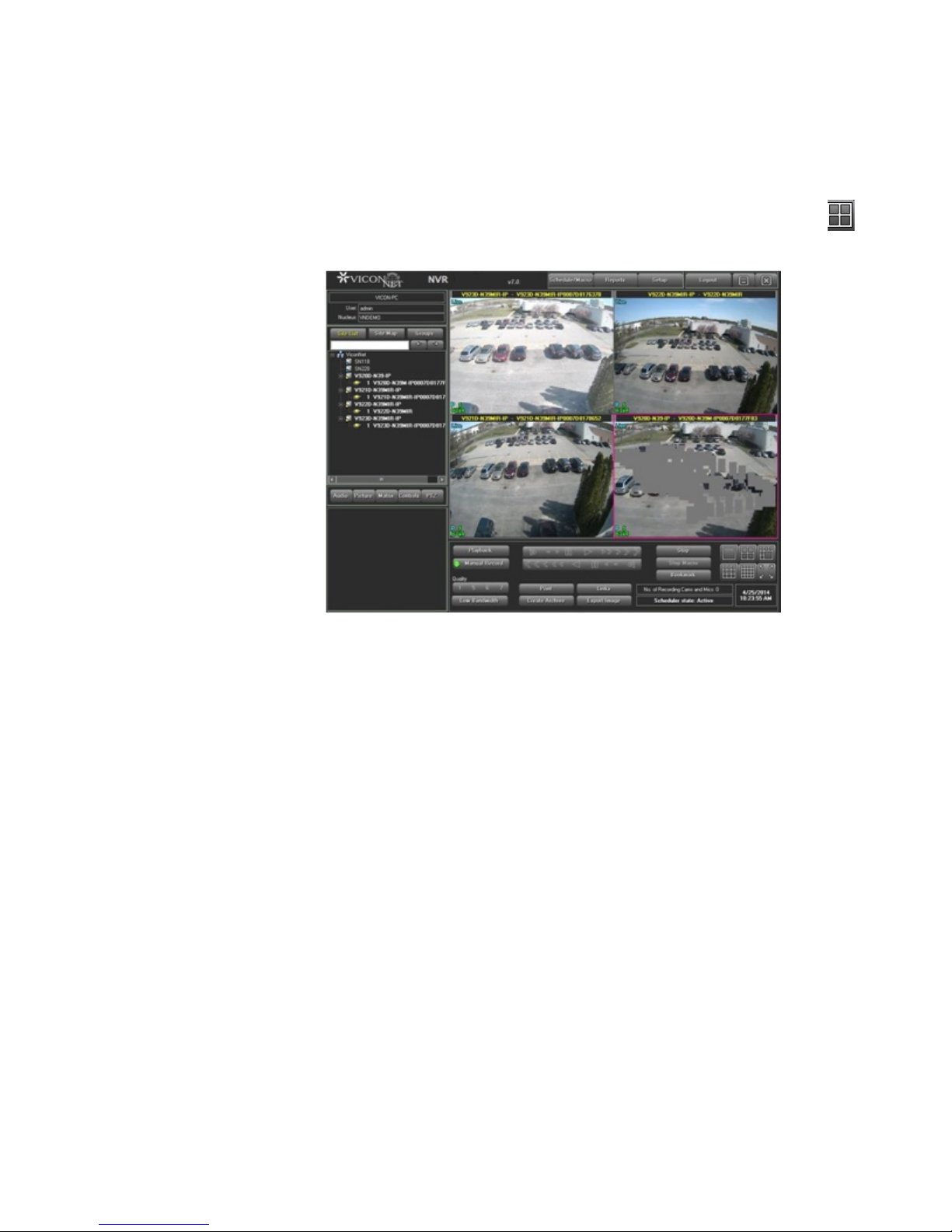
The following example shows the Video Display area after the Four
display mode has been selected.
TIP: You can maximize an individual v ide o display location in the Video
Display area by double-clicking the required location. Double-clicking
again reverts back to the prev ious view.
Step 2: Selecting Cameras and Microphones
After launching the Vicon Net s ystem, in order to view live video and audio
in the Video Display area, you must first s elect the device (camera or
microphone) that transmits the required data.
Use the Site List, Site Map or Groups List to s ele ct devices for viewing
and listening to live video and audio by navigating through the list and
selecting the required devices.
Selecting a device from the list aut omatically begins the device operation
(video and audio transmis sion) in the selected video display location in the
Main window.
As transmission begins, t he appropriate controls for t he s pecific type of
device that you selected become active in the Control Dialog Display area,
which enables you to modify t he liv e video and audio.
Page 20
Quick Guide | 19
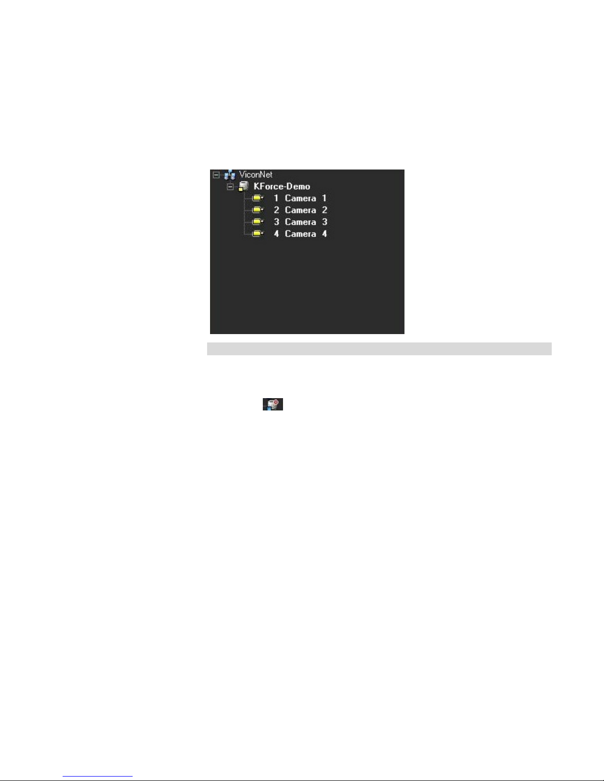
To select a device using t he Sit e Li st:
1. In the Main window, select t he appr opriate display mode, as descri bed
in the previous section.
2. Expand the required trans m it t er t o display a list of the currently
connected cameras and m icrophones.
Note:
The cameras and microphones that appear in the Site List are
automatically detected by t he s ystem during startup. If a camera is
disconnected while it is act ive (meaning being displayed or r ecor ded) , a
red X icon ( ) is displayed next to the relevant c amera in the Site List.
3. Select the required device from the Site List in one of the following
ways:
• Select a video display location and then the required camera. The
live video transmission is disp layed automatically in the s el ected
location, and the camera or m icrophone icon appears highlight ed.
• Select ALL devices from a single transmitter by dr aggin g and
dropping the transmitter anywhere in the Video Display ar ea.
Page 21
20 | Quick Guide
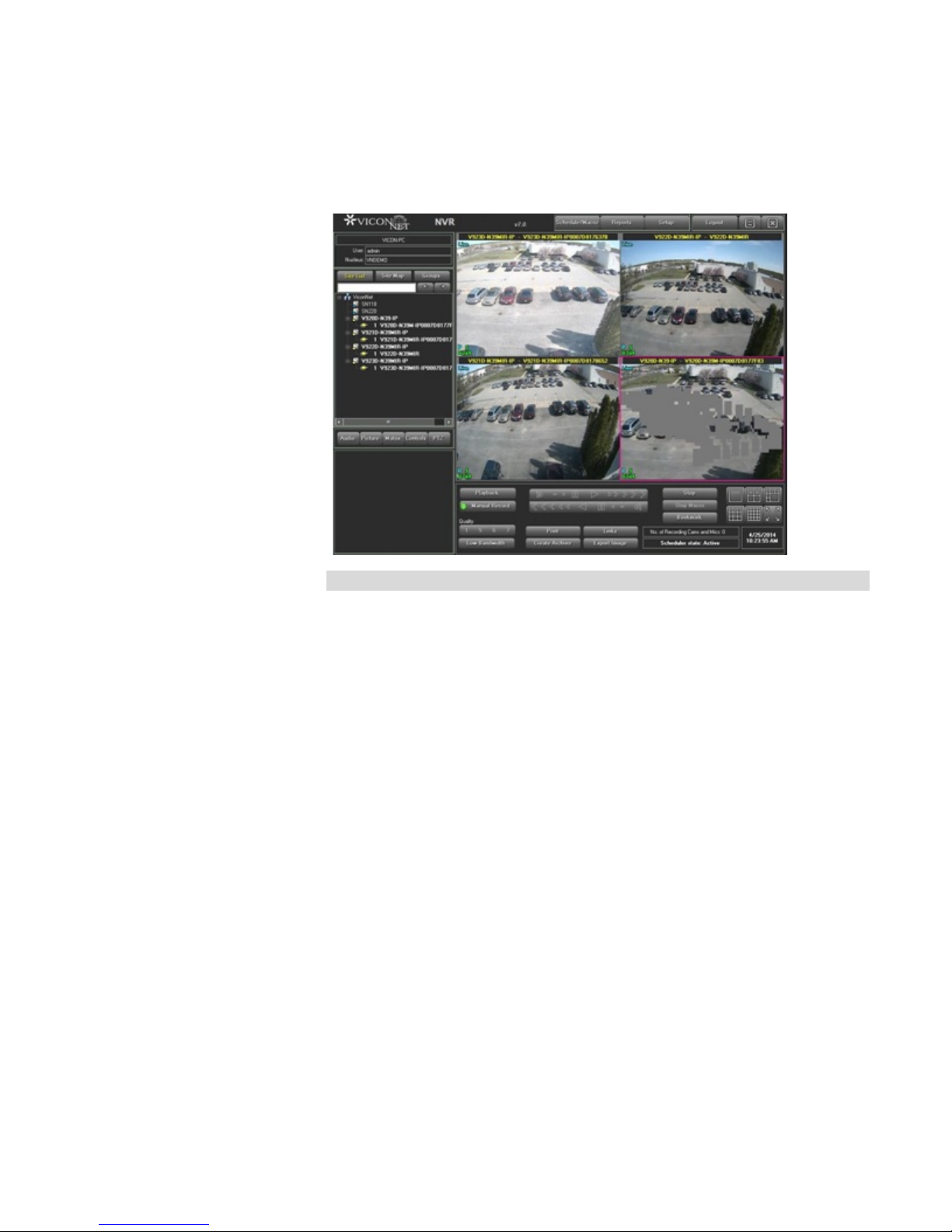
The following example shows four live video transmiss ion s dis played in
the Video Display area. The na me o f e ac h camera is located in the top of
each video display location.
Note
You can manually stop the tr ansmission at any time by clicking STOP.
Page 22
Quick Guide | 21
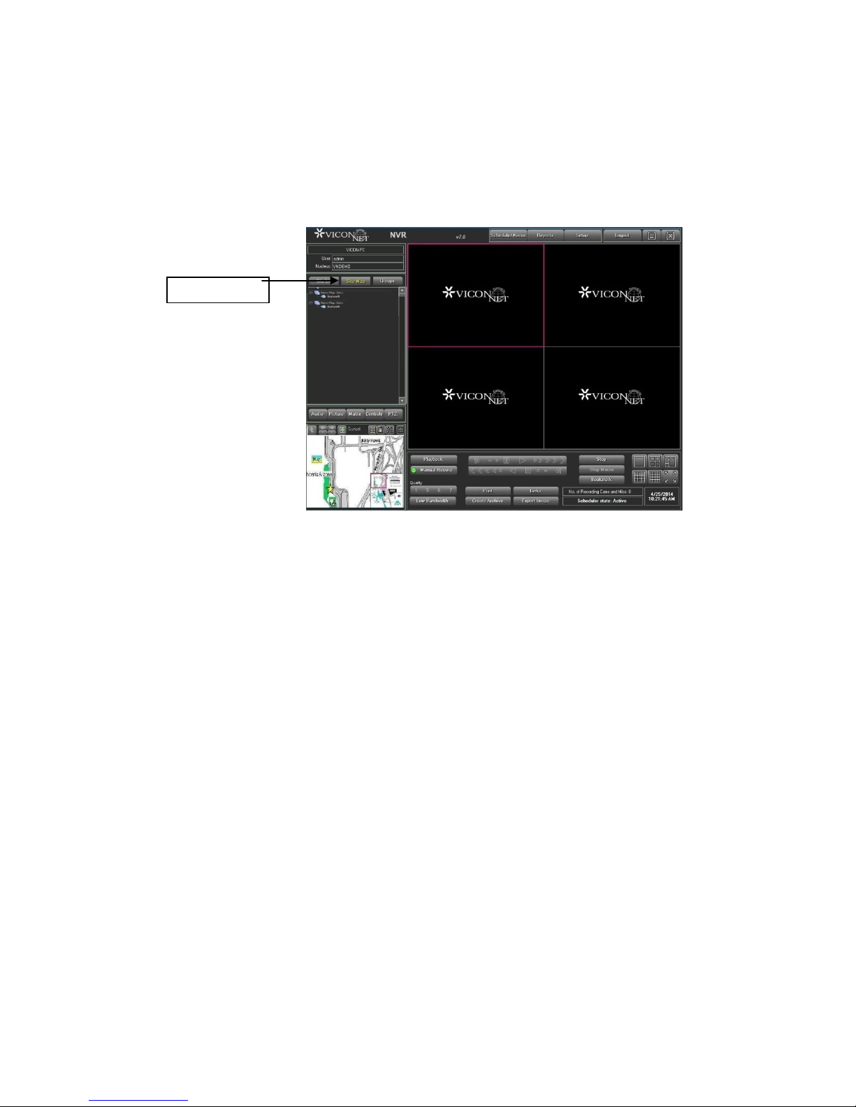
Site Map Tab
Use the Site Map to select cam er as from a drawing, map or set of maps
without having to know to which t r ansmitter it is connected. The Site Map
can be navigated in a similar way to Site List. However, the devices in the
Site Map list are organized by maps, meaning by physical locat ion of
devices as opposed to by dev ice name.
To select a device using t he Sit e Map:
1. In the Main window, select t he Site Map tab.
2. Select a camera by clicking it in the Site Map tab. The lower-left
panel changes according t o t he obj ect selected in the site map.
The picture can be dragged t o t he middle of the editing space, and
then expanded or navigated. The video is displayed in the display
location indicated by the pink border. As an alternative, drag and
drop a camera in the requir ed display location.
3. Devices (cameras, servers, and so on) can be added to a site map
by dragging them directly to where they are located on the map o f
the physical location.
Page 23
22 | Quick Guide
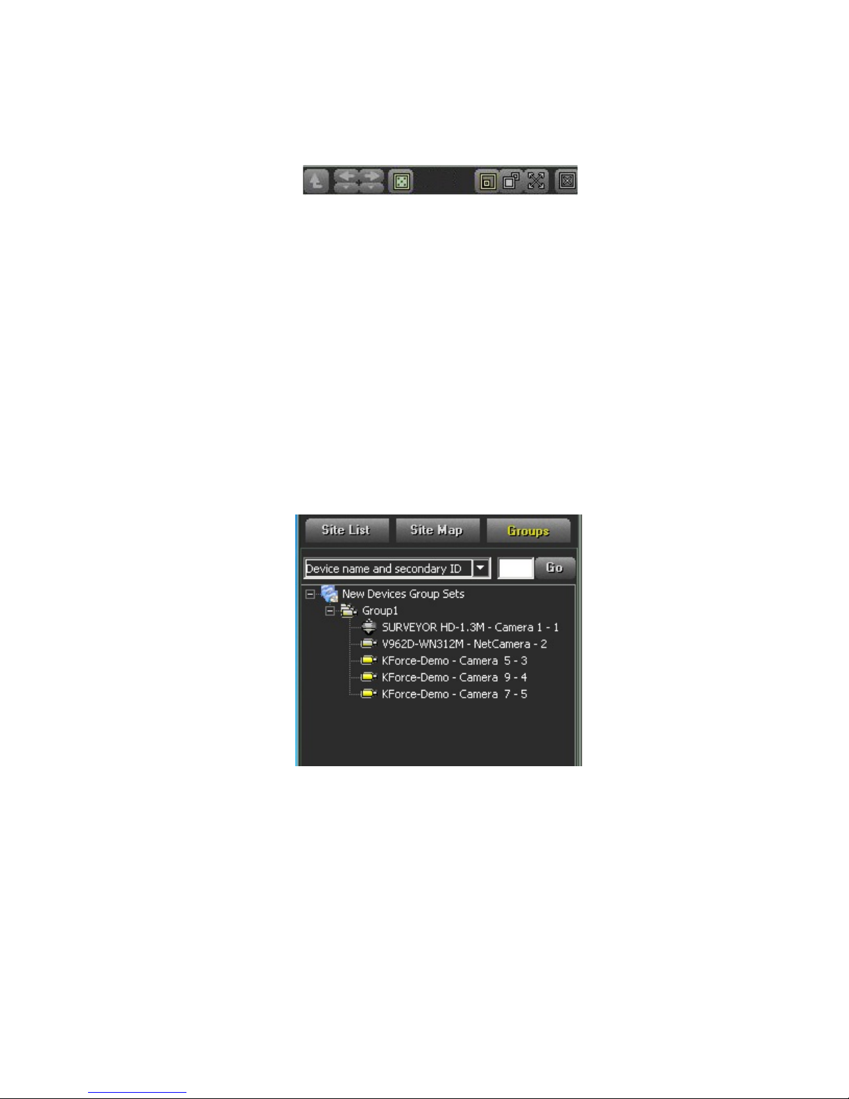
The following options are available for working with the sel ect ed map in
the map set:
From left to right, these co nt r ols ar e for:
• Navig ate to the parent map
• Navig ate to other maps in the map set
• Rem ove text from the map
• Expand the map
• Return t he map to its previous state (expansion)
• Maxi m iz e the map to fit the entire screen
• Close the map image and return to t he Site List tab
The Groups list is a hierar c hic al t ree like the Site List, which display s t he
transmitters and devices connected to your ViconNe t system. The devices
in the Groups list are organized by log ical groups and group sets, where
each group can consist of ca meras and microphones from mu ltiple distinct
transmitters.
You can define your groups and group sets by selecting Devices Group
Sets from the System Settings w indow. Groups are loaded in to the
system using the Add New Group utility.
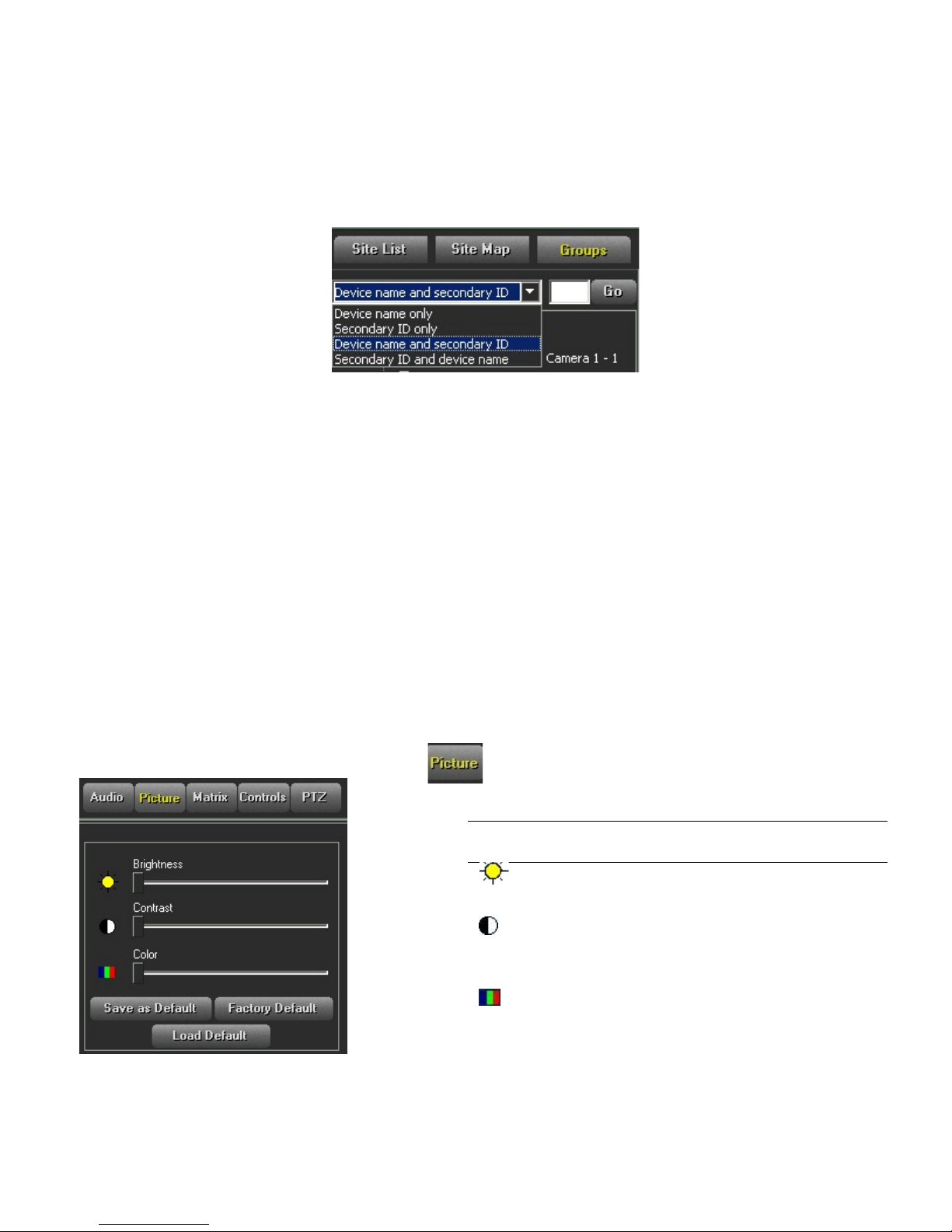
In the Groups list, you can select t o l ist t he devices by name, second ar y
ID (as configured in the Groups Sets Management window ) or bot h.
Page 24
Quick Guide | 23
To select whether to displ ay device name, secondary ID or both:
In the Groups list select the r equired option from the dropdown list and
click Go.
To view a camera or hear a microphone from the Groups list:
Select a camera/microphone in the Groups list or drag and drop it from the
list to the Video Display area or enter the device’s secondary ID in the Go
box and click Go.
The icon appears highligh ted in yellow. The live video tr ansmission/audio
transmission begins; video is displayed in the selected location in the
Video Display area. The pink bor der in t he Video Display area
automatically moves to the next available display loc at ion.
Step 3: Controlling the Picture
The ViconNet system ena bles you to control and change the s et t ings of
the current live pictures di splayed in the Main window, such as the
brightness and contrast. Any changes that you make to the pict ur e
settings affect the data that is cur r ent ly being viewed or recorded.
To control the pic t ure brightness, contrast and c olor:
1. Click . The picture controls are displayed in the Control
Dialog Display area.
2. Move the sliders to adjust the pictur e.
Option Description
Brightness
Contrast
Adjusts the light level on the display
screen.
Adjusts the difference between the
lightest and darkest areas on the
display screen.
Color
Adjusts the color intensity (amount
of white contained in the basic
colors) on the display screen.
Page 25
24 | Quick Guide
To control the live picture quality:
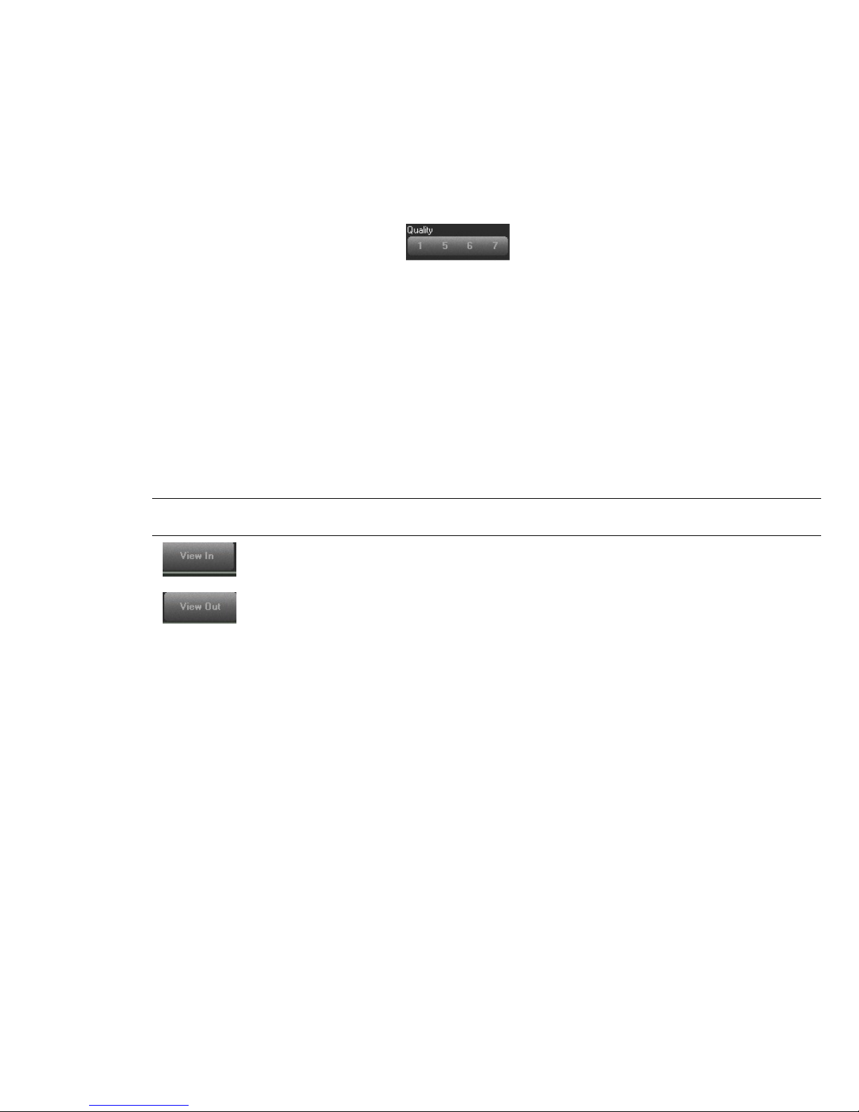
In order to improve transm ission speed, the maximum quality of live
images is set automatica lly according to the selected display mode. The
Single mode is assigned the highest available resolution, w hi le ot her
modes are assigned lesser r esolut i ons, in proportion to their nu mber of
views. When the buttons in the Main window Function
Controls area are enabled, you can manually overrid e t he display
mode - determined live p icture quality for the currently selected camera.
Step 4: Zooming the Video Display
Zooming in or out of a specific vide o display location in the Main window
consists of selecting the required video display location with the left mouse
button and then using the mouse r oller to increase or decrease t he degr ee
of zoom. When the video disp lay is zoomed, one click on the mous e r ol ler
returns the display to its or iginal size.
The zoom function can be used on all types of video (live, recorded, and
playback).
Option Description
Zooms in on the selected segment in order to fine-tune t he selection capability and
simultaneously updates the Time Interval Map accordingly.
Zooms out of the selected segment. The Time Interval Map area returns to its
previous display status.
Page 26
Step 4: Operating a PTZ Camera
From the ViconNet Main window you can easily operate and control a ny
PTZ camera configured in your system. All PTZ functions are performed
and are available only for one selected PTZ camera at a time.
To operate a PTZ camera:
1. Ensure that the PTZ came r a has been configured in the system.
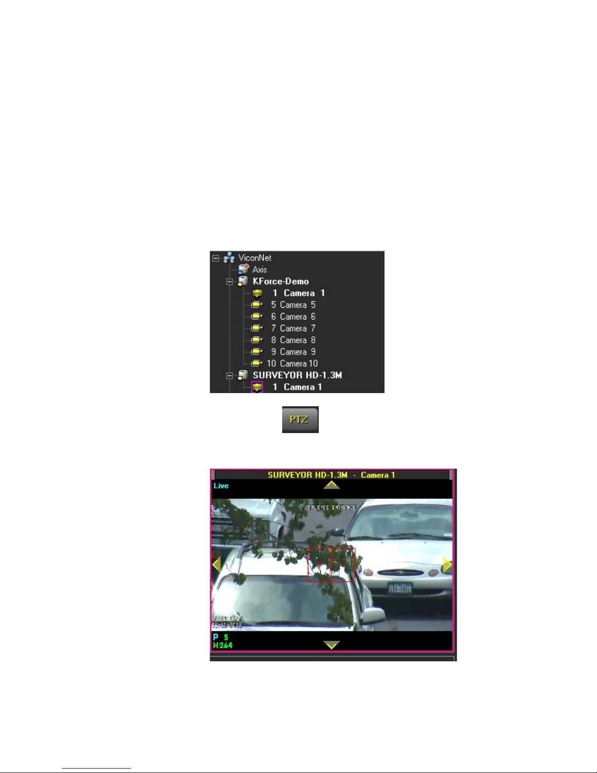
2. Select the required PTZ c am er a from the Site List or Video Display
area.
Quick Guide | 25
3. Click the button. The live video from the selected c amera
is displayed in the Video Display ar ea with a red zoom control box
and yellow direction arrow s.
4. Use the PTZ controls in the video disp lay location, as follows:
Page 27
26 | Quick Guide
To zoom in or out from the center o f t he dis played video, click the plus (+) or
1
4
2
6
7
8
Option Description
Yellow
Direction
Arrows
Optical
Zoom
These arrows serve only as direction markers.
Clicking anywhere in the vide o dis play will cause the camera to mov e in t hat
direction. If you move the mous e (while still holding down the mou s e but t on) ,
the camera will follow the mouse.
When using the mouse, the clos er t he m ouse is to the center, the slower the
camera movement. The farther away the mouse is from the c ent er , t he faster
the camera movement.
minus (-) symbols of the icon.
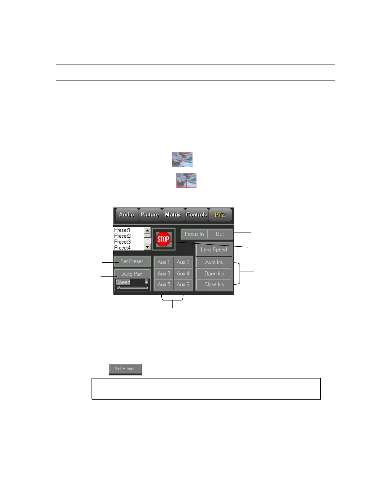
5. Click the icon. The following PTZ cont r ols are displayed in
the Control D ialog Display area:
Option Description
1 The Preset options in the scroll list represent fixed points i n the video display.
When a preset is clicked, t he view automatically focuses on t he associated
view area.
You can define (or reassign) a preset, as follows:
Select the required preset from the scroll list.
Move to the required specific area/zoom using the window navigation functions.
Click
to lock the selected preset to the current location/zoom.
NOTE: Up to 99 presets (depending on the camera's model) may be defined. Vic onNet
recommends that users define a maximum of 80 presets in order to prevent conflict
with some cameras advanced functions.
2 Locks the selected preset t o t he cur r ent location/zoom.
3 Sets the PTZ camera to autom atically rotate around 360° while displaying the
video.
Page 28

Quick Guide | 27
Option Description
4 Determines the speed of the auto pan.
5 Stops uncontrolled directional movement of the video displ ay.
6 Configures Vicon PTZ settings.
7 Adjusts the focus.
8 Controls the amount of lig ht ent er ing behind the PTZ lens. This affect s your
ability to observe the proxim ity of objects to one another in the v ide o display
location, as follows:
Automatically adjusts t he l ight t o t he displayed video.
Adds more light to the displayed video.
Reduces the light in the displayed video.
Page 29
28 | Quick Guide
5
4
3
2
Recorded
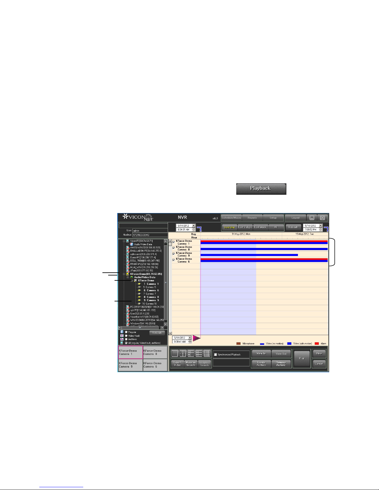
Playing Back Recorded Video/Audio
The ViconNet system ena bles you to select and play back recorded video
and audio segments that hav e been s t or ed in defined storage locatio ns.
You can play back data that was recorded manually or that was recorded
automatically as a result of an a larm event or a preconfigured sc hedule.
You can playback recorde d video and audio either using the Navigator
window or using the Quick Playback option in the Main window.
Step 1: Selecting Recor ded Vi deo/Audio
The first step for playing back recorded video and audio is selecting the
recorded video/audio seg me nt to be played back.
To select recorded video/audio:
1. From the Main window, click . The Navigator
window is displayed, as follows:
Data
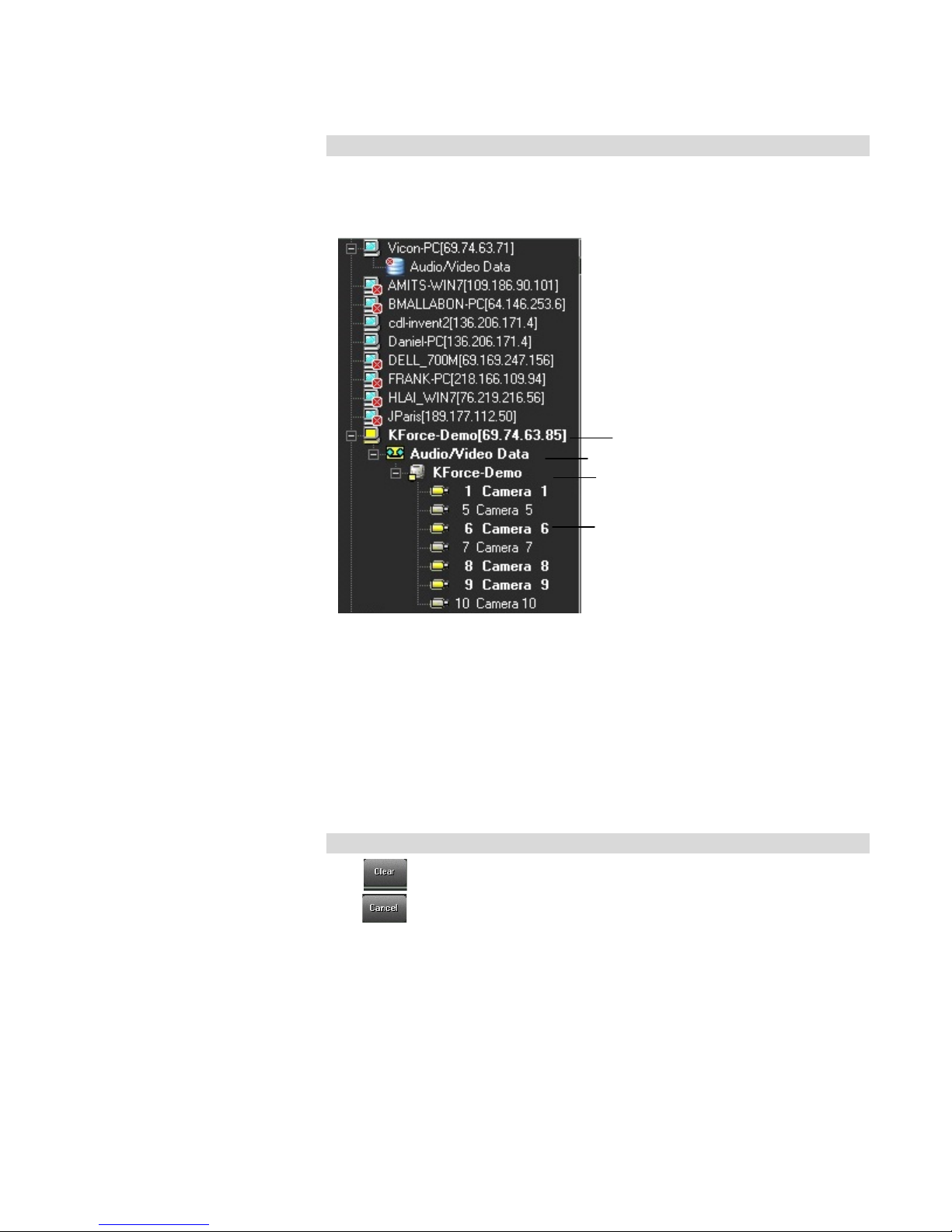
2. Expand the Navigator List to display a list of the system's av ailable
storage locations and archives, if any.
3. Expand a storage location or ar chive to display the list of
connected transmitters.
4. Expand the required trans m it t er t o display the list of recorded
cameras and microphones.
Page 30
Quick Guide | 29
Storage Location
AVDB (Storage Type) Contents
Transmitter
Recorded Devices
Note
You can select (optional) the r equired viewing option from the Navigator
List Controls (Regular, Archives, or Both). The Navigator List is upd at ed
depending on your selection.
Select a camera/microphone either from the Navigator List or by using
standard drag and drop functionality. (A microphone is sel ected by clicking
its list icon.) When you select a device for viewing and playback, a scan of
that storage location is pe r formed for that device's recorde d data, which is
then displayed graphical ly.
5. To select additional recor ded cameras or a microphone, repeat
step 5, as required. Each device you select appears in both the
Recorded Device Contents area and in the Main Window Display
Location area.
Note
The button clears the current Navigator wi ndow settings.
The button closes the Navigator window and reinstates the Main
window.
Page 31
30 | Quick Guide
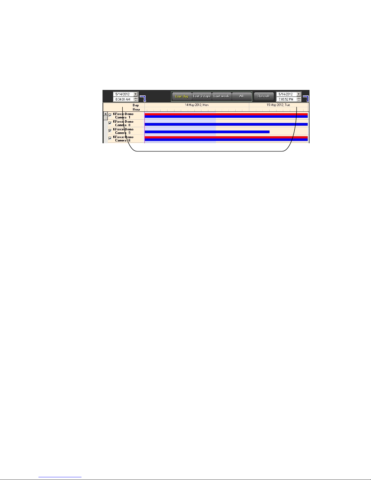
Time Interval Controls – Start Ti me and End Time
Step 2: Selecting the Playback Time Interval
The playback time interval is the range of time for the recorded video and
audio segment you want to view and play back.
You can select a specific time period, defined by its start and end time, for
the recorded segment(s) by:
• Using o ne of the time interval tabs, w hich enable you to select a
range of time;
• OR
• Using the t ime interval controls, which enable you to specify an
exact date and time.
If required, repeat the time inter val selection with a shorter ti me interval to
zoom in further on the select ed r ecorded segment.
For detailed instructions on how to select the playback time inter val, refer
to the full Software Manual.
Step 3: Selecting the Playback Start Time
The ViconNet system provides an option to select the pl ayback start time
by either zooming in on a spec ific recorded segment or by selecting the
exact playback point in the recor ded segment, including hour, minute, and
second, if required.
This option enables you to play back only the required portion o f the
recorded segment instead of having to play the entire seg ment.
To select the playback st art t i m e:
1. (Optional) Zoom in on a speci fic recorded segment, as follows:
• In t he Recor ded Dev ice Content s area, position the mouse point er
to the left or right of the recorded s egment of which you want t o
zoom in.
• Mark the recorded segment by holding down the left mouse button
and dragging the mouse pointer over the recorded segment until
the blue shading covers the ent ire r ecorded segment, as follows:
Page 32
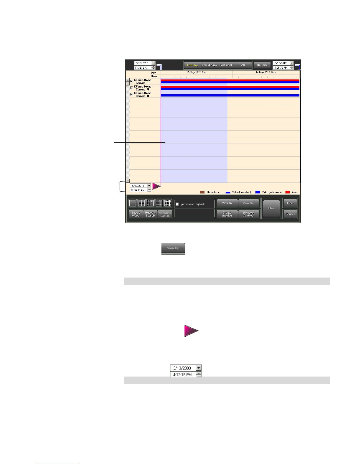
2
1
(Light
area)
blue
Quick Guide | 31
• Click to zoom in on the marked recorded segment.
• Repeat t he pr evious two sub-steps (mark a nd zoom) to zoom in
further on the selected recor ded segment, if required.
Note
If you have selected more than one device in the Recorded Devic e
Contents area, all recorded segments for all devices in the m arked
(shaded) area will be zoomed in o n s i m ultaneously.
2. Select the playback start t i me by using the mouse pointer to click
and slide the pink arrow to the exact locat ion (including the
hour, minute, and second) in the r ecor ded segment.
OR
You can also set the playbac k start t ime by using the time interval
controls on the bottom-left side of the window.
Note
When you click on the pink arrow, a tooltip appears, displaying the date
and time of its current location in t he r ecorded segment(s). This enables
you to pinpoint the exact playback start time.
Page 33
32 | Quick Guide
Step 4: Displaying Recorded Video/Audio Content
The next step is to view the actual recorded segments in the Main window.
Each recorded video seg ment is displayed in a video display location
according to the paramete r s t hat you selected in the previous steps.
To display r ec or ded video/audio content:
• In t he Navigator window, ensure that the pink arrow is positioned
at the required playback start time for the selected cameras, as
described in the previous st ep.
Note
If you do not need to play back from a specific start time, ens ur e that the
pink arrow is to the far left of the Recor ded Dev ice Conte nts area.
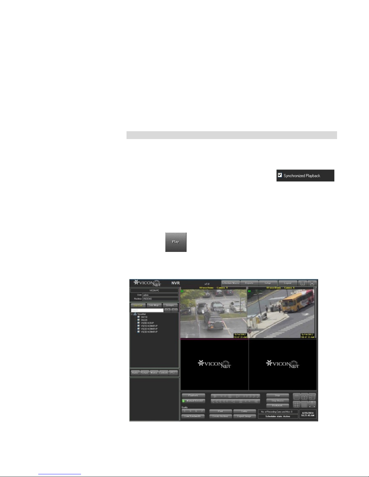
• (Optional) If you want to play the r ecor ded segments for all the
selected devices simultaneously, select the
checkbox.
If this option is not selected, t hen t he playback controls will apply to only
one selected camera or microphone at a time. That device is selected by
clicking its block in the Main Wind ow Disp lay Locatio n ar ea. ( The selected
block has a pink border.) The Main window playback controls then apply
only to the selected camera/microphone.
• Click . The Navigator window closes, and the first frame o f
the recorded segment(s) f or each s elected camera and
microphone is displayed in t he Main window in its selected display
location, as shown below:
Page 34

Each recorded segment a ppear s in its selected display location with its
camera source informati on (date, time, and camera name). The segments
are paused and the playbac k controls are now enabled.
Step 4: Playing Back from a Selecte d Ca mera/Microphone
The ViconNet system ena bles you to simultaneously play back recorded
video and audio segments in t he Main wind ow from either a single or all
currently displayed recorded cameras or microphon es , depending on the
selection you made in Step 4: Displayi ng Recor ded Video/ Aud io Content ,
To play back from a select ed camera/microphone:
1. In the Main window, select t he video display location that contains
the recorded segment that you want to play back.
2. Click the Forward button . The selected recorded segment
plays, and the camera source det ails change accordingly.
If you selected the Synchronized Playback checkbox, all the video and
audio segments for the display ed cameras/microphone p lay
simultaneously.
Quick Guide | 33
Page 35
34 | Quick Guide
1
x50, x100
frame
4
5
frame
8
9
5
4
2 1 3 6 7 8 9
9
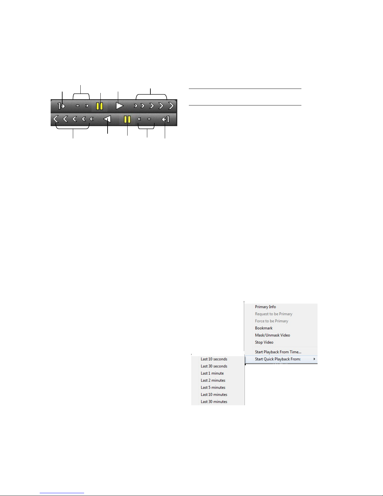
3. (Optional) Use the playback buttons to navigate through the
recorded segment(s) duri ng playback, as required.
Quick Playback
Option Description
2
Play Forward
Forward x2, x5, x10,
3
6
7
Forward – frame by
Forward x¼, x½
Play Reverse
Reverse x2, x5, x10,
x50, x100
Reverse – frame by
Reverse x¼, x½
Pause
The following options are available for quick playback of vide os:
• Start Playback From Time
• Start Quick Playback From
• Move Playback To Time
Page 36

Quick Guide | 35
To perform quick playback (Start Quick Playback From, Start
Playback From Time):
In the Main window, right-click in the required camera disp lay location.
Select Start Quick Playback From, and the number of seconds from the
current moment from which you want to play back.
OR
Select Start Playback From Time, and a calendar is displayed to select
the date to playback the v ideo.
The playback is shown in the adjacent video display location.
If no recording is associat ed w it h t he selected time (for example, the
current recording started more recently than one minute ago, or t he most
updated video is 30 minut es old), a warning is displayed.
Museum Search
To change the play back time or to stop quick playback
To playback currently playing video at another time, select Move
Playback To Time, and a calendar is displayed to select the date to
playback the video.
To stop the quick playbac k, right-click and select Stop Video.
The Museum Search opt i on enables you to search for activity in a
specific camera's data within a defined region of the database. You can
locate all the video segment s that include a specific differenc e, for
example, a main door openin g, or a car being moved.
The Museum Search opt i on enables you to locate the follow i ng t ypes
change entities:
• Detections: Speci fi c frames where significant changes occurred.
• Episodes: Sets of consecutive frames in which significant
changes that determine a uni que event are detected.
Page 37
36 | Quick Guide
To perform a museum search:
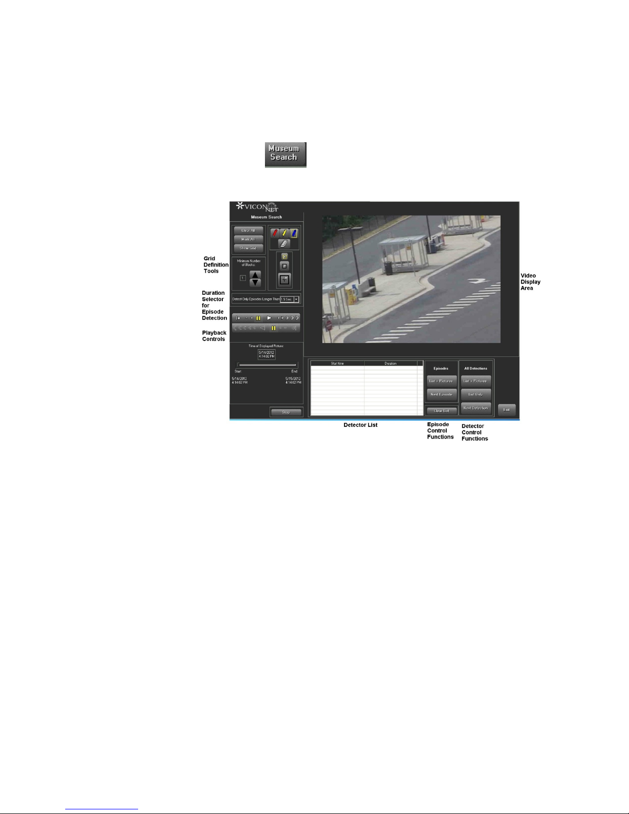
1. In the Navigator window, ensur e that the required camera an d time
interval are selected.
2. Click the button. The Museum Search window is displayed.
The Video Display area shows the first frame of the selected ti me
interval. (The Time Range area shows the selected time inter val start and
end times.) When the Mus eum Search window is opened, blue-colored
grid blocks cover the entir e frame in the Video Display area, in di c at in g
that the change detection me chanism currently applies t o the entire
frame area.
3. If required, navigate to a relevant frame in the segment using t he
playback controls.
4. Define the ROIs relevant for the current search procedures. This is
done using the following gr id de fi nition tools.
Page 38
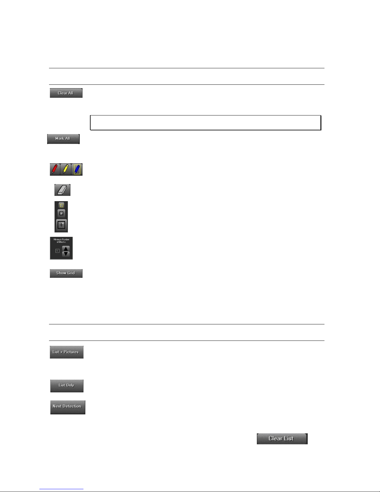
Option Description
Quick Guide | 37
This button clears all the curr ent col or ed grid blocks in the view. You c an
then use the Pencil tool to define grid blocks for specific ROI s within the
display view surface.
NOTE: Change detection does not function unless ROIs are identified by colored grid
blocks.
This button marks colored gr id blocks over the entire window surface,
meaning that change dete ction will apply to the entire camera view. You can
then use the Eraser tool to remove specific grid blocks.
Use the Pencil tool to define ROIs by clicking and dragging over the required
view area segments, thereby drawing arrays of colored gr id b locks.
Use the eraser tool to erase RO I segments by clicking and dragg ing ov er
selected grid blocks.
Use the Tool Size Select ors to select the Pencil/Eraser t ool size. According
to the selected size, the cur sor dr aws/erases a small (single block), medium
(4-block) or large (16-block) width of surface blocks per sweep.
Use the Minimum Number of Blocks selector to define how many blocks of
the colored grid arrays must be simultaneously invol ved in the change,
compared to the reference frame, for a detection to be recog niz ed (most
sensitive = 1, least sensitive = 16).
Use the Show Grid button to apply a gray planning grid to the ar eas of the
window where no ROIs are def in ed. This grid is for viewing purpos es only
and does not affect the change-detection process. When selected, the button
changes into a Hide Grid button.
5. To find specific frames wher e changes occurred in already de fined
Option Description
Starts a search, from the cur r ent frame forward, for any fra mes i n w hich
significant differences in ROIs (based on the Minimum Number of Blocks
selection) are detected. A s each difference frame is detected, t he frame
image is displayed in the Video Display area.
Performs the same action s as t he List + Pictures b ut ton, but does not
display the frame images.
Searches for and display each next frame (one frame each time the button
is clicked) in which there is an applicable difference.
You can clear the Detection list by clicking the button.
ROIs, use the Detector Control functions, as follows:
Page 39
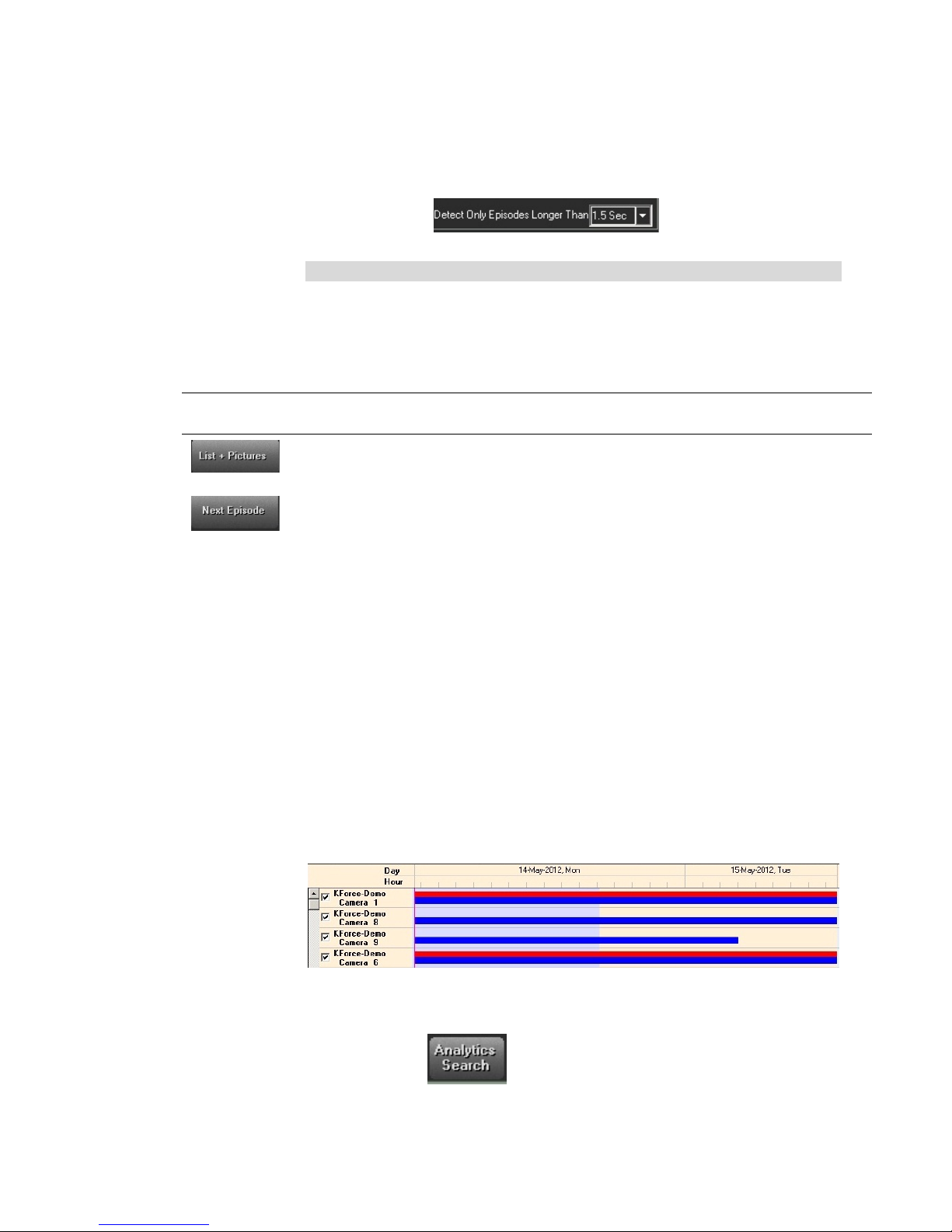
6. If you want to find "episodes" ( set s of consecutive frames in
Blue shading indicates sel ected Time Interval
which a significant differe nce in RO I s is detected), do the
following:
• From the dropdown list, select
the length of time over whi ch c hanges must continuously occur.
Note
The default duration is 1.5 s econds. Values from 0.1 seconds t o 5. 0
seconds can be selected. I n gener al, the shorter the duration, the more
easily episodes will be detect ed.
• Use the Episode Control functions, as follows:
Option Description
38 | Quick Guide
Video Analytics
This button starts a searc h for episodes, from the current frame forward.
As each episode is detect ed, its fir st frame image is displayed in the
Video Display area.
This button is used to searc h for each next episode (one episode each
time the button is clicked).
You can run the frames of an epis ode by clicking on its entry in the
Detection List. Light blue bloc ks indicate the detected differen ces in the
frame.
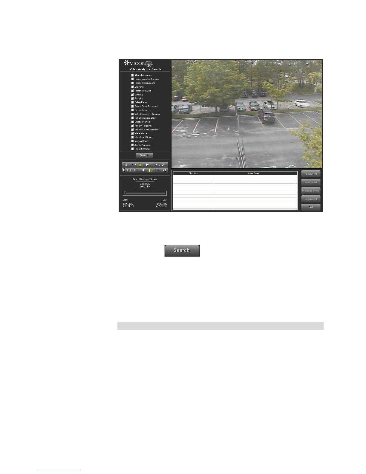
The Analytics Search option enables you to view a specific camera’s
detected suspicious activity collected from a specific time period
(ViconNet VI must be part of the s ystem).
1. In the Navigator window, ensur e that the required camera is
selected. (Only one camera can be selected at a time.)
2. In the Recorded Devices Content area, select the required time
interval by clicking and dr agging.
3. Click the button. The Analytics Search window is
displayed.
Page 40
Quick Guide | 39
4. From the list provided, select which behaviors are to be searched
for (All Analytics will automatically check all behaviors ) .
5. Click the button. A list of behavior violations will
display at the bottom of the scr een.
6. Click the event you want to display. A slider visually represents at
what point in the selected time s pan each behavior violation
occurred. Click Next Event to view the next violation in the list or
select another one from the list. Playback Controls are displayed
and can be used as needed.
7. Click Exit to exit the screen.
Note
Video Analytics Engine must be set for this utility to function.
Page 41
Creating Archives
40 | Quick Guide
The ViconNet system enables you to create archives, w hich contain
selected recorded data fro m a v ideo database. This consists o f sel ect ing
the specific devices, the s pecific recorded data, and the destination
location for where you wa nt t o save the data. You can then view it at a
later time.
Note
After creating an archive, you can perform all playback functi ons on the
archived data in the same way that you can with regular recorded data,
as described beginning from the Selecting Recorded Video/Audio
section.
To create an archive:
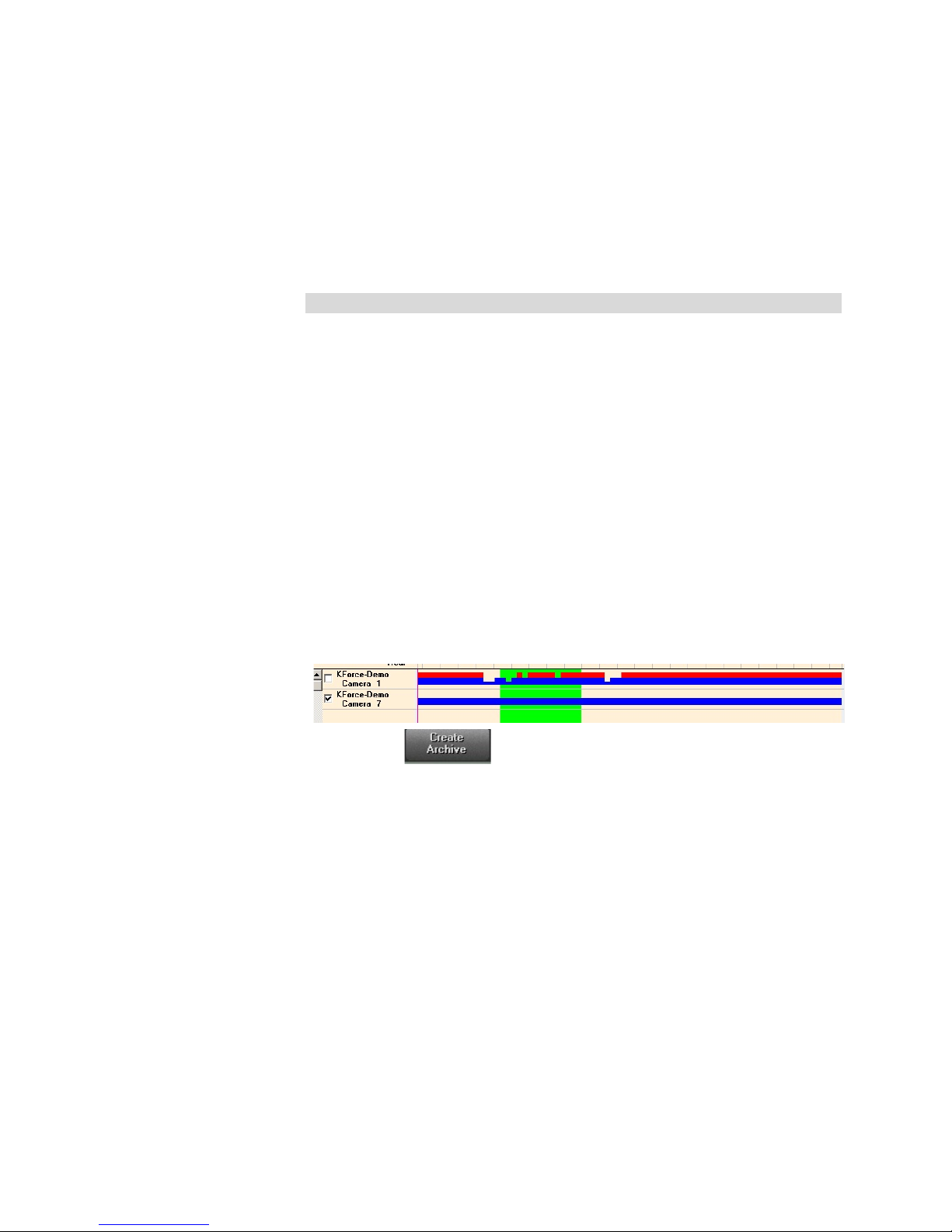
From the Navigator list, s elect the camera(s) and/or m icrophone(s) that
contain the recorded data t hat you want to archive.
1. In the Recorded Device Contents ar ea, mark the recorded
segments that you want to archive by holding down the left
mouse button and draggin g t he m ouse pointer over the required
segments.
2. The selection area is indicat ed with a lime green shading, and t he
size of the selected conte nts is displayed at the top of the Archiv e
area in the Estimated archive size field (in MB).
3. Click . The selection area is indicated with a lime
green shading, and the size of the selected contents is displayed
at the top of the Archive area in the Estimated archive size field
(in MB).The Navigator List is replaced by an Archive area, which
automatically displays t he archive date and time at the bottom.
Page 42
Quick Guide | 41
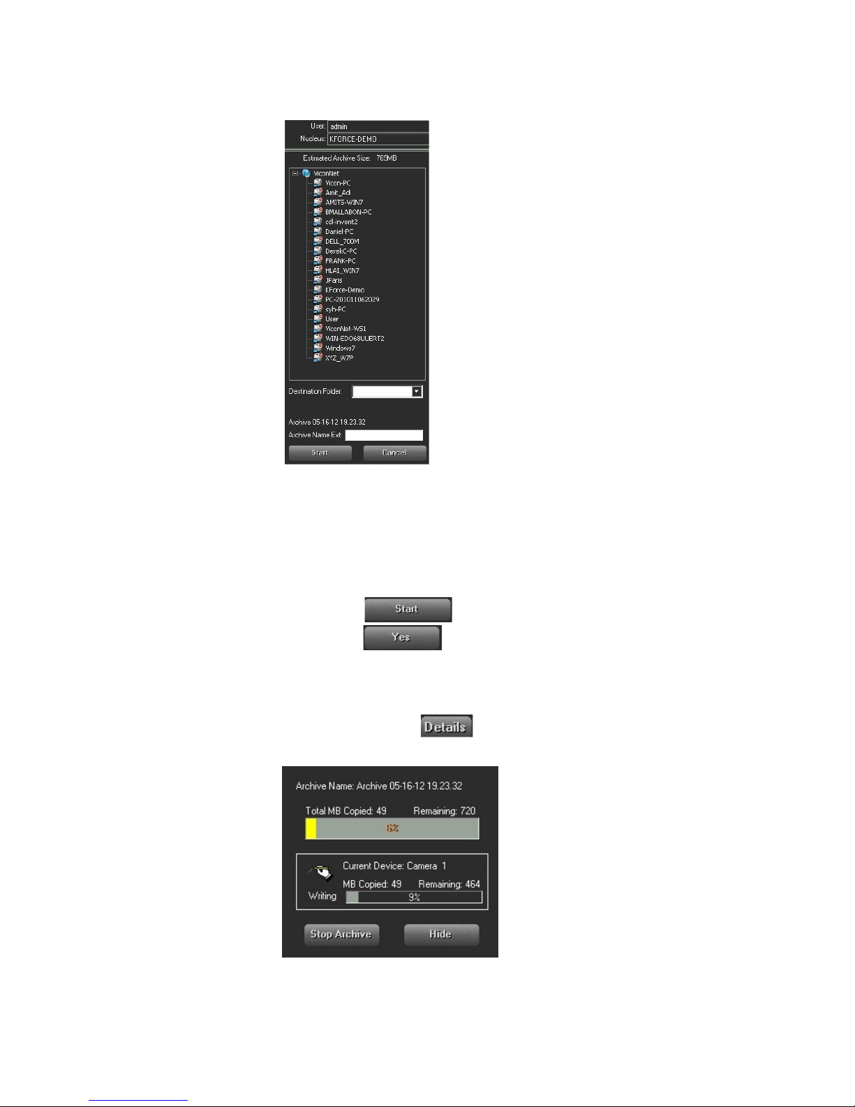
4. In the Archive area, navig at e t o the required archive destination
(network path, CD-ROM or DVD device). The destinat ion d etails
are displayed automatically at the bottom of the Archive area.
5. In the Archive Name Ext field, enter a logical archive name. The
archive name is automatically added to the archive date and time
details.
6. Click . A confirmation message is displayed.
7. Click to confirm archiving. A progress bar in t he
Archive Controls area indic at es t hat the archive creation is in
process.
8. (Optional) To view additional details during the archive creation
process, click
. The relevant details are display ed in the
Control Dialog Display area, as shown in the following example:
Page 43
42 | Quick Guide
Note
If required, you can stop the ar chive creation process by clic kin g Stop
Archive.
9. When the Archive compl et ed successfully message is
displayed, click .
The new archive is displa yed in the Navigator List with an Archive icon
(instead of a database icon ), as well as a list of its contents.
All playback functions can now be performed, as described in the
previous sections in this c hapt er .
To remove an archive:
1. From the Navigator List, select the required archive.
2. Click . A confirmation prompt is disp layed.
3. Click to confirm the action. The archive is deleted from
the database.
Printing/Exporting Frames and Creating Video Clips
Digital recording continu ously writes video and audio dat a to different
types of temporary storage. After this temporary stor age f il ls u p, the
oldest data is overwritten. Thi s c hapter describes the methods offered by
ViconNet for permanently st or ing old recorded video and audio data
before it is overwritten.
Printing Frames
You can print out the Main window Video Display area panel, sh owing
the frames currently being displayed in Live or Playback mode.
To print a selected frame:
1. Display live video (as des cr ibe d in Viewing and Listening to Liv e
Video/Audio) and/or play back the required cameras (as
described in Playing Back Recorded Video/Audio).
2. If you require a specific frame fro m a p layback camera, navigate
to the required frame usin g t he playback controls and freeze the
view on that frame using the Stop/Pause button.
3. Click the button. A standard Print window is
displayed.
4. Select the printer and settings.
5. Click OK to print out the Video Disp lay area panel with its current
contents.
Page 44
Exporting Frames
Quick Guide | 43
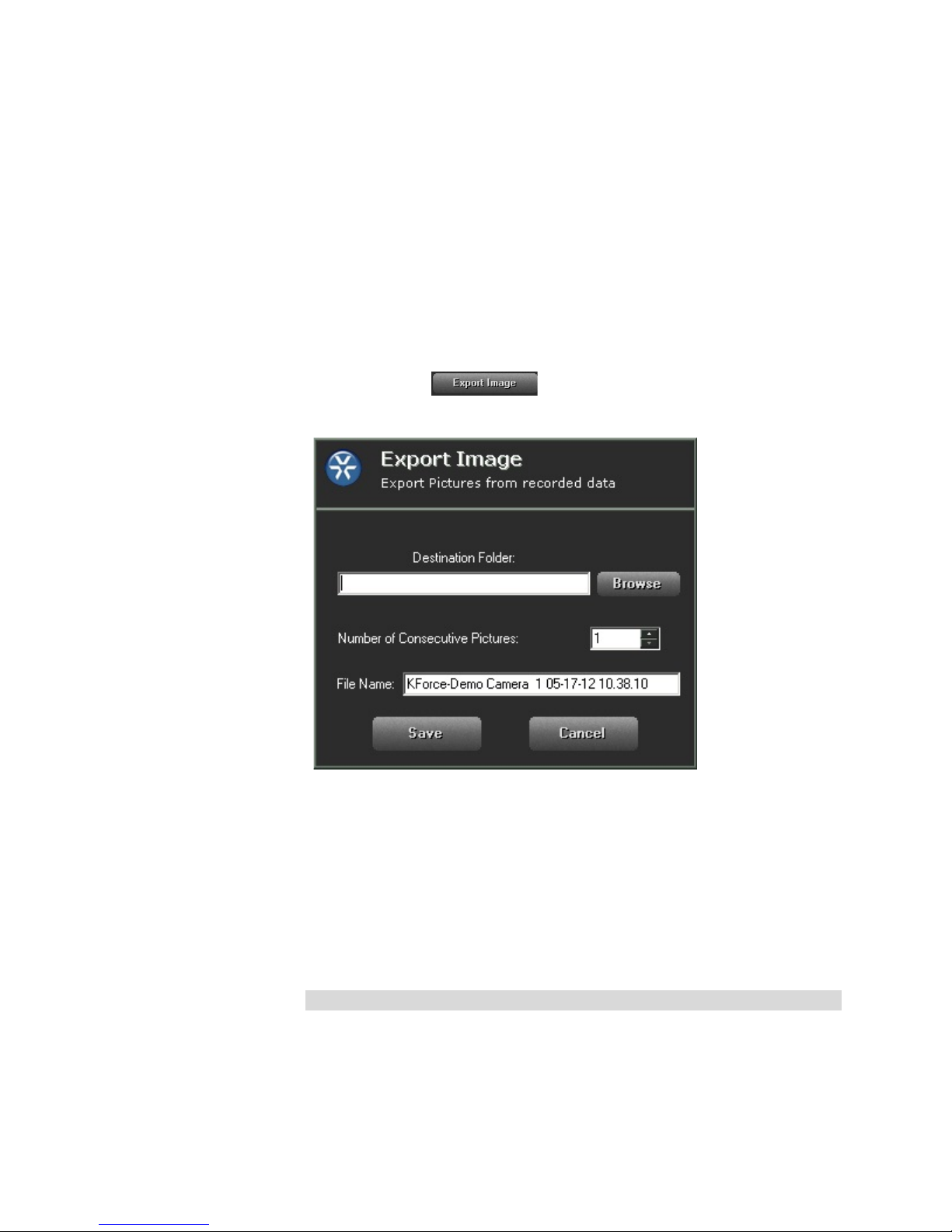
You can save selected single frames or groups of consecutive frames
being viewed in playback to any network destination as JPEG i ma ges.
To export a selected fra m e:
1. Play back the required ca mera, as described in Playing Bac k
Recorded Video/Audio.
2. In the ViconNet Main window, navigat e t o t he r equired frame
using the playback control s and freeze the view on that frame
using the Stop/Pause button.
3. Click the button. The Export Pictures window is
displayed.
4. Enter the required destination path on your network.
5. Specify the number of consecutive frames, including the cur r ent
frame, from which JPEG ima ges should be created (up to 9999).
6. Enter a base file name in the File Nam e field. (Do not include the
file extension. The requested files are automatically named using
the base name plus a suffix to denot e t he applicable frame
number.)
7. Click Save to save the requested imag es t o the selected location.
Note:
If Cancel is clicked while the Export is in process, the frames t hat w er e
already exported up to that point w il l not be r emoved from the destination
folder.
Page 45
Creating Video Clips
44 | Quick Guide
You can create a short video using t he various video formats from a
selected playback segme nt , which can then be viewed using Windows
Media Player. The video scr een converter utility allows conversion of any
video/audio data into standard/common format, enabling you to
view/listen to the data with standard video/audio tool s .
Note:
This should not be used if you r equire t he ability to authenticate your
video in a court of law.
To create a video file:
1. In the Navigator window, select a single camera and/or
microphone and the required playback time interval, as described
in Playing Back Recorded Video/Audio. (Only one cam er a in the
Recorded Device Contents area should have a checkmark.)
2. In the Recorded Device C ontents area, highlight the r ecor ded
segments that you want to create a video file for by holdin g down
the left mouse button and dragging the mouse pointer over t he
required segments.
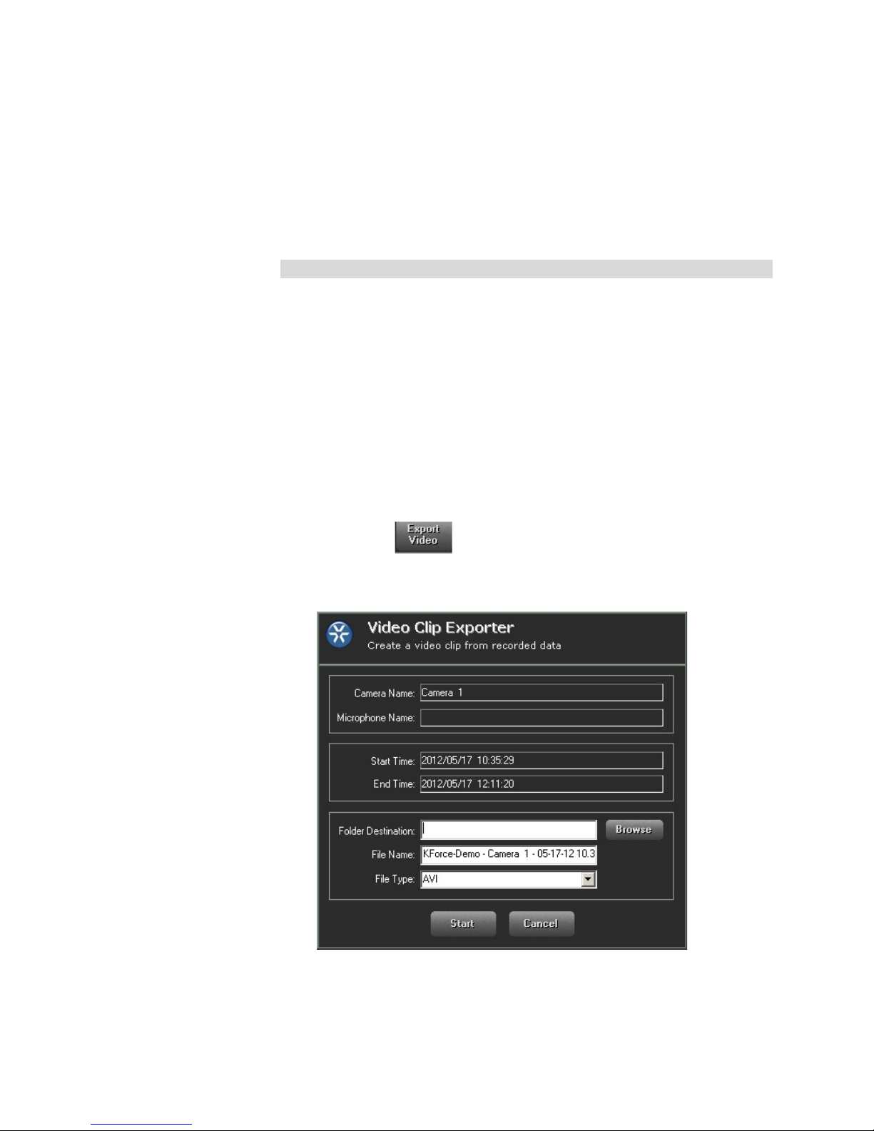
3. Click the button. The Video Clip Exporter window is
displayed. Your camera, microphone and time interval selections
are shown in read-only fields.
4. Enter the required destination path on your network and a base
file name in the File Name field. ( D o not include the file
extension.)
Page 46

Quick Guide | 45
5. Select the File Type from t he dropdown list: AVI, MPEG-4, DivX
(requires codec installati on) or xVid.
Note
Video recorded in MPEG-4 and H.264 compression can only be exported
to MPEG-4 or Xvid. Vid eo created from ViconNet compr es sion or a JPEG
recording (i.e., I-Onyx and 3rd party cameras) can also create AVI files as
well as MPEG-4 or Xvid.
6. Click Start to create the v ideo clip at t he selected location.
Page 47
Help
46 | Quick Guide
ViconNet provides an integrated Help window. Press t he F1 key and a
popup window will display; expand the window to find links t o al l relevant
ViconNet documentation and tutorial videos.
Using the Web Viewer
Since the VN-NVR-JUMP is not cap able of local display, the ViconNet
Web Viewer can be used to view cameras.
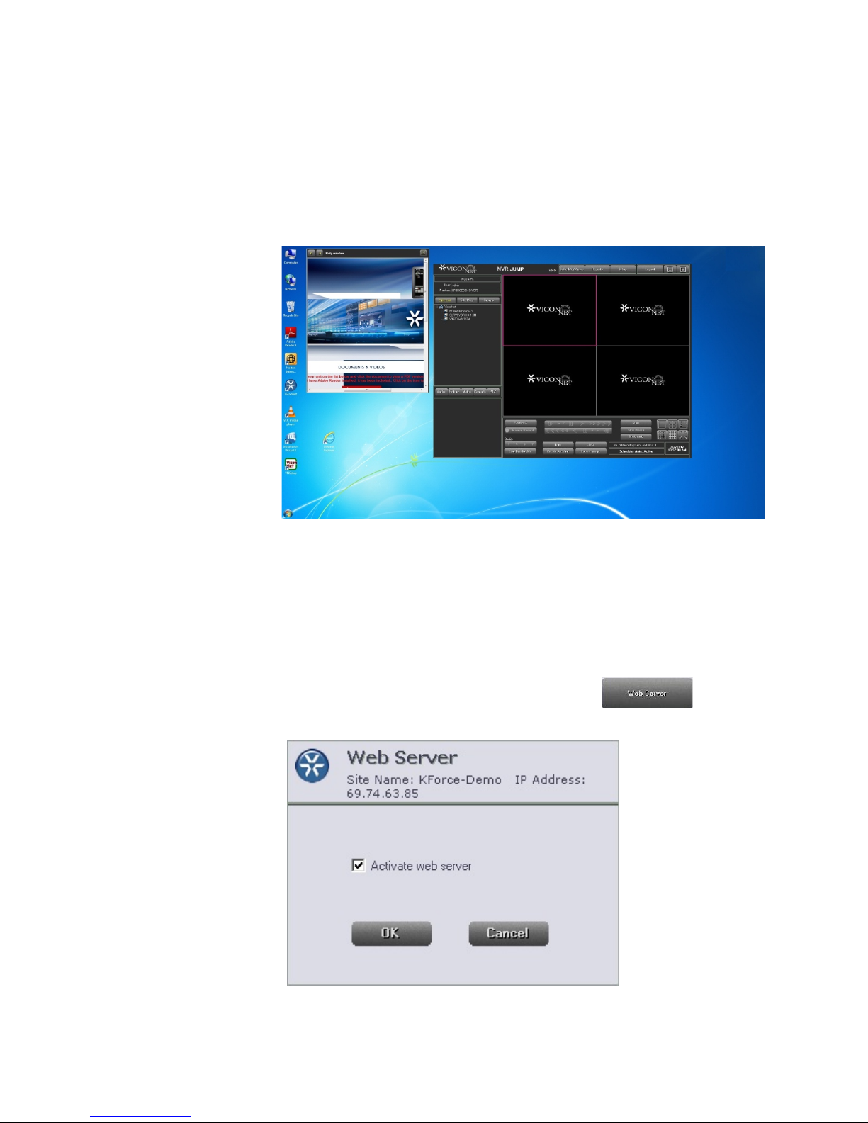
Before the Web Viewer can be used, a Web Server must be setup. This
is done through the VIcon Net software. Click the button
from the System Sett ings window; activate the Web Server and click OK..
Page 48
Quick Guide | 47
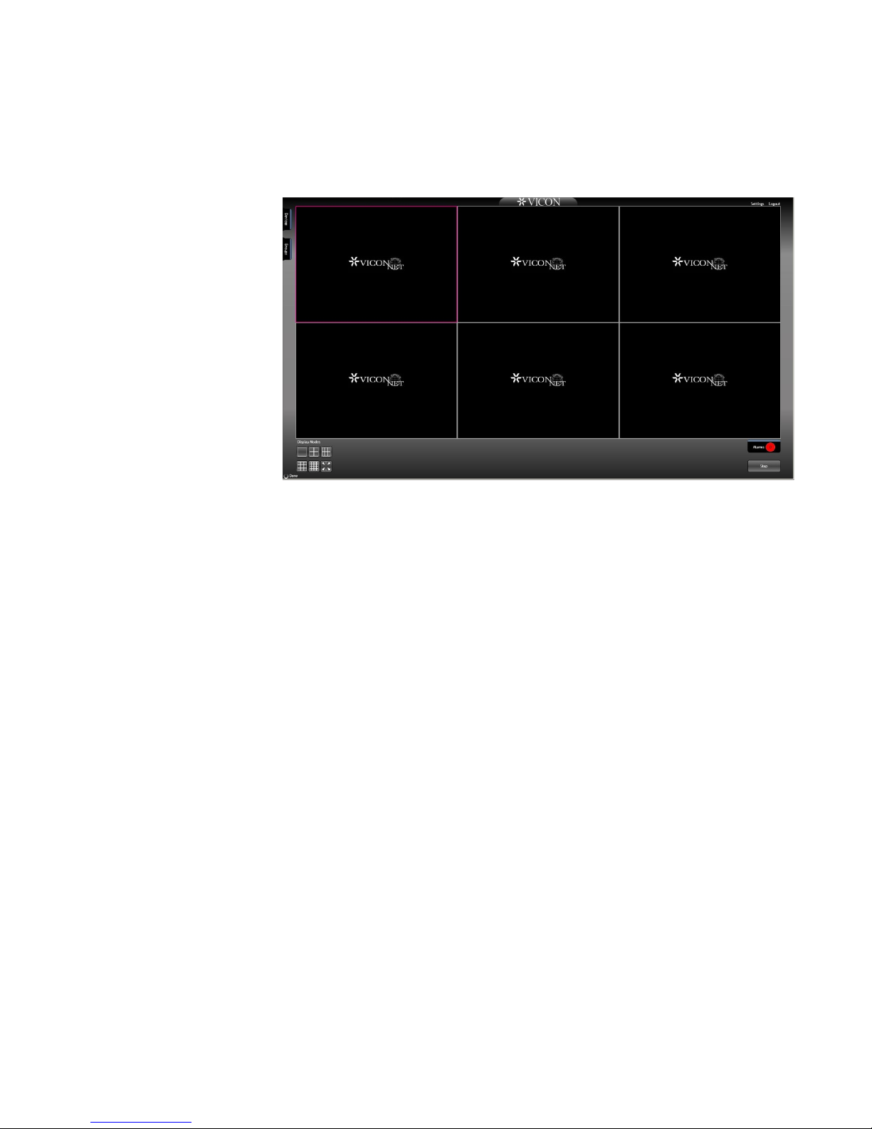
The Web Viewer (client) will run by browsing to the JUMP's IP address.
After login, the Main screen disp lays. The Web Viewer Main screen
provides all the tools needed t o work with the ViconNet system.
Page 49

Shipping Instr u cti o ns
Use the following procedure when returning a unit to the factory:
1. Call or write Vicon for a Return Authorization (R.A.) at one of the locations listed below.
Record the name of the Vicon employee who issued the R.A.
Vicon Industries Inc.
131 Heartland Boulevard
Edgewood, NY 11717
Phone: 631-952-2288; Toll-Free: 1-800-645-9116; Fax: 631-951-2288
For service or returns from countries in Europe, contact:
Vicon Industries (U.K.) Ltd
Brunel Way
Fareham, PO15 5TX
United Kingdom
Phone: +44 (0)1489/566300; Fax: +44 (0)1489/566322
2. Attach a sheet of paper to the unit with the following information:
a. Name and address of the company returning the unit
b. Name of the Vicon employee who issued the R.A.
c. R. A. number
d. Brief description of the installation
e. Complete description of the problem and circumstances under which it occurs
f. Unit’s original date of purchase, if still under warranty
3. Pack the unit carefully. Use the original shipping carton or its equivalent for maximum
protection.
4. Mark the R.A. number on the outside of the carton on the shipping label.
Page 50

Vicon Standard Equipment Warranty
Vicon Industries Inc. (the “Company”) warrants your equipment to be free from defects in material and
workmanship under Normal Use from the date of original retail purchase for a period of three years, with the
following exceptions:
1. Uninterruptible Power Supplies: Two years from date of original retail purchase.
2. VDR-700 Recorder Series: One year from date of original retail purchase.
3. V5616MUX: One year from date of original retail purchase.
4. Arecont Cameras: One year from date of original retail purchase.
5. FMC series fiber-optic media converters and associated accessories: Lifetime warranty.
6. For PTZ cameras, “Normal Use” excludes prolonged use of lens and pan-and-tilt motors, gear
heads, and gears due to continuous use of “autopan” or “tour” modes of operation. Such
continuous operation is outside the scope of this warranty.
7. Any product sold as “special” or not listed in Vicon’s commercial price list: One year from date of
original retail purchase.
Date of retail purchase is the date original end-user takes possession of the equipment, or, at the sole
discretion of the Company, the date the equipment first becomes operational by the original end-user.
The sole remedy under this Warranty is that defective equipment be repaired or (at the Company’s option)
replaced, at Company repair centers, provided the equipment has been authorized for return by the
Company, and the return shipment is prepaid in accor da nce with policy.
The Company will not be obligated to repair or replace equipment s howing abuse or damage, or to parts
which in the judgment of the Company are not defective, or any equipment which m ay have been tampered
with, altered, misused, or been subject to unauthorized repair.
Software supplied either separately or in hardware is furnished on an “As Is” basis. Vicon does not
warrant that such software shall be error (bug) free. Softw are support via telephone, if provided at
no cost, may be discontinued at any time without notice at Vicon’s sole discretion. Vicon reserves
the right to make changes to its software in any of its products at any time and without notice.
This Warranty is in lieu of all other conditions and warranties express or implied as to the Goods,
including any warranty of merchantability or fitness and the remedy specified in this Warranty is in
lieu of all other remedies available to the Purchaser.
No one is authorized to assume any liability on behalf of the Company, or impose any obligations on it in
connection with the sale of any Goods, other than that which is specified above. In no event will the
Company be liable for indirect, special, incidental, consequential, or other damages, whether arising from
interrupted equipment operation, loss of data, replacement of equipment or software, costs or repairs
undertaken by the Purchaser, or other causes.
This warranty applies to all sales made by the Company or its dealers and shall be governed by the laws of
New York State without regard to its conflict of laws principles. This Warranty shall be enforceable against
the Company only in the courts located in the State of New York.
The form of this Warranty is effective July 1, 2014.
THE TERMS OF THIS WARRANTY APPLY ONLY TO SALES MADE WHILE THIS WARRANTY IS IN
EFFECT. THIS WARRANTY SHALL BE OF NO EFFECT IF AT THE TIME OF SALE A DIFFERENT
WARRANTY IS POSTED ON THE COMPANY’S WEBSITE, WWW.VICON-SECURITY.COM. IN THAT
EVENT, THE TERMS OF THE POSTED WARRANTY SHALL APPLY EXCLUSIVELY.
Vicon Part Number: 8006-9010-03-11 Rev 0714
Page 51

Vicon Industries Inc.
For office locations, visit the website:
www.vicon-security.com
 Loading...