

Page 1

VDR-208 USER MANUAL
Digital Hard Disk Recorde
r
Vicon Industries Inc. does not warrant that the functions contained in this equipment will meet your
requirements or that the operation will be entirely error free or perform precisely as described in the
documentation. This system has not been designed to be used in life-critical situations and must
not be used for this purpose.
Warning: To prevent fire or shock hazard, do not expose the unit to rain or
moisture.
Copyright © 2005 Vicon Industries Inc. All rights reserved.
Product specifications subject to change without notice.
Vicon and its logo are registered trademarks of Vicon Industries Inc.
VICON INDUSTRIES INC., 89 ARKAY DRIVE, HAUPPAUGE, NY 11788
TEL: 631-952-CCTV (2288) FAX: 631-951-CCTV (2288)
TOLL FREE: 800-645-9116
24-Hour Technical Support: 800-34-VICON (800-348-4266)
UK: 44 (0) 1489-566300 WEB: www.vicon-cctv.com
Vicon part number 8009-8165-30-01 Rev.1106
Page 2

Page 3
2
To prevent fire or shock hazard, do not expose the unit to rain
or moisture.
The symbol is intended to alert the user to the presence of important operating and
maintenance (servicing) instructions in the literature accompanying the unit.
The symbol is intended to alert the user to the presence of uninsulated "dangerous
voltage" within the product's enclosure that may be of sufficient magnitude to constitute a
risk of electric shock to persons.
Warning -- This equipment has been tested and found to comply with the limits for a Class A digital
device, pursuant to part 15 of the FCC Rules. These limits are designed to provide reasonable
protection against harmful interference when the equipment is operated in a commercial environment.
This equipment generates, uses, and can radiate radio frequency energy and, if not installed and used
in accordance with the instruction manual, may cause harmful interference to radio communications.
Operation of this equipment in a residential area is likely to cause harmful interference in which case
the user will be required to correct the interference at its own expense.
Warning – If TIMEKEEPER NVRAM IC that is consist of RTC, SRAM, POWER-FAIL CONTROL
CIRCUIT and BATTERY is replaced, the replacement is to be done by a trained technician with the
same type of component.
Caution -- Any changes or modifications in construction of this device which are not expressly
approved by the party responsible for compliance could void the user's authority to operate the
equipment.
WARNING
Page 4

3
Warranty will be made void if the product is disassembled or manipulated by the user.
Safety Instructions
1) Read these instructions.
2) Keep these instructions.
3) Heed all warnings.
4) Follow all instructions.
5) Do not use this apparatus near water.
6) Clean only with dry cloth.
7) Do not block any ventilation openings.
Install in accordance with the manufacturer’s instructions.
8) Do not install near any heat sources such as radiators,
heat registers, stoves, or other apparatus (including amplifiers)
that produce heat.
9) Do not defeat the safety purpose of the polarized or grounding-
type plug. A polarized plug has two blades with one wider than the other. A grounding type plug has
two blades and a third grounding prong. The wide blade or the third prong is provided for your safety.
If the provided plug does not fit into your outlet, consult an electrician for replacement of the
obsolete outlet.
10) Protect the power cord from being walked on or pinched particularly at plugs, convenience
receptacles, and the point where they exit from the apparatus.
11) Only use attachments/accessories specified by the manufacturer.
12) Use only with the cart, stand, tripod, bracket, or table specified by the manufacturer, or sold
with the apparatus. When a cart is used, use caution when moving the cart/apparatus
combination to avoid injury from tip-over.
13) Unplug this apparatus during lightning storms or when unused for long periods of time.
14) Refer all servicing to qualified service personnel. Servicing is required when the apparatus
has been damaged in any way, such as power-supply cord or plug is damaged, liquid has been
spilled or objects have fallen into the apparatus, the apparatus has been exposed to rain or
moisture, does not operate normally, or has been dropped.
Page 5

2
Table of contents
1. SYSTEM OVERVIEWS ..........................................................10
1.1 S
AFETY
................................................................................................................................10
1.2 P
ACKING LIST
...................................................................................................................... 12
1.2.1 Components......................................................................................................................... 12
1.2.2 Options ................................................................................................................................ 12
1.3 F
EATURES & SPECIFICATIONS
............................................................................................... 13
1.3.1 Features ............................................................................................................................... 13
1.3.2 Specifications ...................................................................................................................... 14
1.4 N
AME, FUNCTION & CONNECTIONS
..................................................................................... 15
1.4.1 Front view ........................................................................................................................... 15
1.4.2 Rear panel view................................................................................................................... 18
1.4.3 Remote controller function.................................................................................................. 19
1.5 INSTALLATION................................................................................................................. 21
1.5.1 Installation and connection.................................................................................................. 21
1.5.2 Camera ................................................................................................................................ 21
1.5.3 Video Out ............................................................................................................................ 22
1.5.4 Audio................................................................................................................................... 22
1.5.5 RS-232................................................................................................................................. 22
1.5.6 PTZ/AUX/ALARM ............................................................................................................ 22
1.5.6.1
RS-485+, RS-485- .............................................................................................................................. 22
1.5.6.2
AUX 1~5 ............................................................................................................................................ 22
1.5.6.3
Alarm Out (NO, COM, NC) ............................................................................................................... 22
1.5.6.4
Sensor 1~8 .......................................................................................................................................... 23
1.5.7 Network............................................................................................................................... 23
1.5.8 USB flash memory.............................................................................................................. 23
2. BASIC OPERATION PROCEDURES ................................... 24
2.1 P
OWER ON/OFF
.................................................................................................................... 24
2.1.1 Power ON............................................................................................................................ 24
2.1.2 Power OFF .......................................................................................................................... 24
2.2 D
ATE & TIME SETTING
......................................................................................................... 24
Page 6

3
2.3 C
HANGE OF LIVE VIDEO CHANNEL IN MUX MODE
................................................................ 24
2.4 P
ASSWORD SETTING PROCEDURE
.......................................................................................... 24
2.5 N
ETWORK SETTING
.............................................................................................................. 25
2.6 R
ECORDING
.......................................................................................................................... 25
2.6.1 Recording types................................................................................................................... 25
2.6.2 Recording modes.................................................................................................................25
2.7 P
LAYBACK
........................................................................................................................... 25
2.7.1 Press the Play button ...........................................................................................................25
2.7.2 Audio files........................................................................................................................... 25
2.8 S
EARCH
................................................................................................................................25
2.8.1 Search mode........................................................................................................................ 25
2.8.2 Search method..................................................................................................................... 26
2.9 B
ACKUP
............................................................................................................................... 26
2.9.1 CD-RW................................................................................................................................ 26
2.9.2 USB flash memory.............................................................................................................. 26
2.10 N
ETWORK
............................................................................................................................ 26
2.11 C
LIENT PROGRAM
................................................................................................................ 26
2.11.1 RAMS (Remote Access & Monitoring System) ................................................................. 26
2.11.2 UniPlayer............................................................................................................................. 27
2.11.3 MultiViewer ........................................................................................................................ 27
2.11.4 Quick Installer..................................................................................................................... 27
3. MAIN SETUP SCREEN ..........................................................28
3.1 C
AMERA SETUP MENU
......................................................................................................... 28
3.1.1 Channel number................................................................................................................... 29
3.1.2 Camera Name Edit .............................................................................................................. 29
3.1.3 Camera hide ........................................................................................................................ 30
3.1.4 Picture Setting ..................................................................................................................... 30
3.1.4.1
Contrast, Brightness, Hue, .................................................................................................................. 30
3.1.4.2
Default ................................................................................................................................................ 30
3.1.5 PTZ setup ............................................................................................................................ 31
3.1.5.1
Model Number.................................................................................................................................... 31
3.1.5.2
PTZ ID................................................................................................................................................ 32
3.1.5.3
Reverse Control .................................................................................................................................. 32
3.1.5.4
RS-485 Setting.................................................................................................................................... 32
3.1.5.5
TEST................................................................................................................................................... 32
Page 7

4
3.1.5.6
Additional PTZ Menus........................................................................................................................ 32
3.1.6 Sequence time ..................................................................................................................... 34
3.2 R
ECORD SETUP MENU
.......................................................................................................... 34
3.2.1 Resolution ........................................................................................................................... 34
3.2.2 Audio Sync.......................................................................................................................... 34
3.2.3 Channel number ..................................................................................................................35
3.2.4 Quality................................................................................................................................. 35
3.2.5 Frame rate............................................................................................................................ 35
3.2.6 Record mode ....................................................................................................................... 35
3.2.7 Record Schedule Setup........................................................................................................ 36
3.3 E
VENT SETUP MENU
............................................................................................................ 37
3.3.1 Motion Detection Setting .................................................................................................... 37
3.3.1.1
Channel............................................................................................................................................... 38
3.3.1.2
Sensitivity ........................................................................................................................................... 38
3.3.1.3
Detection Zone.................................................................................................................................... 38
3.3.2 Sensor Setting...................................................................................................................... 39
3.3.2.1
Sensor Type......................................................................................................................................... 39
3.3.2.2
Channel Link....................................................................................................................................... 39
3.3.3 Alarm Output ...................................................................................................................... 40
3.3.3.1
Sensor ................................................................................................................................................. 40
3.3.3.2
Motion ................................................................................................................................................ 40
3.3.3.3
Relay Time.......................................................................................................................................... 40
3.3.4 Post Alarm Record Time ..................................................................................................... 40
3.3.5 FTP Setting.......................................................................................................................... 41
3.3.5.1
FTP Server IP address......................................................................................................................... 41
3.3.5.2
ID........................................................................................................................................................ 42
3.3.5.3
Password............................................................................................................................................. 42
3.3.5.4
Target Path .......................................................................................................................................... 43
3.3.5.5
FTP Length of Image (second) ........................................................................................................... 43
3.3.6 FTP Trigger Setting.............................................................................................................43
3.3.6.1
Sensor ................................................................................................................................................. 44
3.3.6.2
Motion ................................................................................................................................................ 44
3.3.7 E-Mail Address Setting ....................................................................................................... 44
3.3.8 E-Mail Setting ..................................................................................................................... 45
3.3.8.1
Send (Period) ...................................................................................................................................... 45
3.3.8.2
Prohibition setting............................................................................................................................... 46
Page 8

5
3.3.8.3
SMTP Server IP address ..................................................................................................................... 46
3.3.8.4
Authentication..................................................................................................................................... 46
3.3.8.5
Password............................................................................................................................................. 46
3.3.8.6
Event Log............................................................................................................................................ 47
3.4 P
LAYBACK SETUP
................................................................................................................ 47
3.4.1 Channel ............................................................................................................................... 47
3.4.2 Starting Point....................................................................................................................... 48
3.4.3 Audio................................................................................................................................... 48
3.5 D
ISPLAY SETUP
.................................................................................................................... 48
3.6 N
ETWORK SETUP
................................................................................................................. 49
3.6.1 DDNS setting ...................................................................................................................... 49
3.6.2 Remote Connection Login Password .................................................................................. 51
3.6.3 Network Type...................................................................................................................... 51
3.6.3.1
Static ................................................................................................................................................... 52
3.6.3.2
DHCP.................................................................................................................................................. 53
3.6.3.3
PPPoE ................................................................................................................................................. 53
3.6.4 Changing the Network configuration.................................................................................. 55
3.7 S
YSTEM SETUP SCREEN
........................................................................................................ 56
3.7.1 DVR Name.......................................................................................................................... 56
3.7.2 System Password.................................................................................................................57
3.7.2.1
Password Setting................................................................................................................................. 57
3.7.2.2
Password Apply .................................................................................................................................. 58
3.7.3 Auto Key Lock.................................................................................................................... 58
3.7.4 Time / Date.......................................................................................................................... 58
3.7.4.1
Set up Time / Date .............................................................................................................................. 59
3.7.4.2
Time / Date Format ............................................................................................................................. 59
3.7.4.3
Day Light Saving Time....................................................................................................................... 59
3.7.5 Buzzer ................................................................................................................................. 60
3.7.6 Language............................................................................................................................. 60
3.7.7 HDD Setup .......................................................................................................................... 60
3.7.7.1
The number of HDD ........................................................................................................................... 61
3.7.7.2
Write Mode......................................................................................................................................... 61
3.7.7.3
Forced Deletion................................................................................................................................... 61
3.7.7.4
Hard Disk............................................................................................................................................ 62
3.7.8 Aux Port .............................................................................................................................. 62
3.7.8.1
Active.................................................................................................................................................. 63
Page 9

6
3.7.8.2
Function .............................................................................................................................................. 63
3.7.9 Factory Default.................................................................................................................... 63
3.7.10 Software Upgrade................................................................................................................64
3.8 B
ACKUP
............................................................................................................................... 65
3.8.1 Backup Device .................................................................................................................... 65
3.8.2 Start Time............................................................................................................................ 65
3.8.3 End Time............................................................................................................................. 65
3.8.4 Channel ............................................................................................................................... 65
3.8.5 Event ................................................................................................................................... 65
3.8.6 Backup Start ........................................................................................................................ 65
3.8.7 Format ................................................................................................................................. 66
3.9 S
YSTEM LOG
........................................................................................................................ 66
3.10 S
YSTEM INFORMATION
......................................................................................................... 67
3.10.1 Video type ........................................................................................................................... 67
3.10.2 H/W version ........................................................................................................................ 67
3.10.3 S/W version......................................................................................................................... 67
3.10.4 KERNEL version ................................................................................................................ 67
3.10.5 Mac Address........................................................................................................................ 67
3.11 S
EARCH MENU
..................................................................................................................... 68
3.11.1 Search by Time.................................................................................................................... 68
3.11.1.1
Starting Time ...................................................................................................................................... 69
3.11.1.2
Ending Time........................................................................................................................................ 69
3.11.1.3
Channel............................................................................................................................................... 69
3.11.1.4
Event................................................................................................................................................... 69
3.11.1.5
Example of Search Result................................................................................................................... 70
3.11.2 Search of still image............................................................................................................ 70
3.11.2.1
Screen of search.................................................................................................................................. 70
3.12 PLAYBACK........................................................................................................................71
3.12.1 PLAYBACK of recorded Images........................................................................................ 71
3.12.2 Method of playback............................................................................................................. 71
3.12.3 Screen of played back. ........................................................................................................ 71
3.12.4 Control during play back..................................................................................................... 72
3.12.5 Playback of still image ........................................................................................................ 73
3.12.5.1
Method of playback ............................................................................................................................ 73
3.12.5.2
Screen of playing back........................................................................................................................ 73
3.12.5.3
Control during Play back .................................................................................................................... 73
Page 10

7
3.12.6 Playback the backed up-image ............................................................................................ 74
3.13 M
ISCELLANEOUS MENU
....................................................................................................... 74
3.13.1 NET..................................................................................................................................... 74
3.13.2 OSD..................................................................................................................................... 75
3.13.3 Audio Mute ......................................................................................................................... 75
3.13.4 HDD .................................................................................................................................... 75
3.13.5 LOG .................................................................................................................................... 75
4. DVR CLIENT PROGRAM......................................................76
4.1 O
VERVIEW OF
DVR ............................................................................................................. 76
4.2 PC
REQUIREMENT (MINIMUM
) ............................................................................................. 76
4.3 I
NSTALLATION & EXECUTION OF PROGRAM
.......................................................................... 76
4.4 RAMS (R
EMOTE ACCESS
& M
ONITORING SYSTEM
) ........................................................... 77
4.4.1 Screen and button................................................................................................................ 77
4.4.2 Connecting to DVR............................................................................................................. 78
4.4.3 UniPlayer link ..................................................................................................................... 79
4.4.4 Full-screen display .............................................................................................................. 79
4.4.5 Program setup...................................................................................................................... 80
4.4.6 DVR recording.................................................................................................................... 80
4.4.7 DVR playback search.......................................................................................................... 82
4.4.8 DVR playback search.......................................................................................................... 82
4.4.9 DVR backup........................................................................................................................ 85
4.4.10 DVR Setting........................................................................................................................ 86
4.4.11 Still image Capture.............................................................................................................. 86
4.4.12 Watermark insertion ............................................................................................................ 87
4.4.13 Printing still image .............................................................................................................. 87
4.4.14 Motion picture recording..................................................................................................... 87
4.4.15 PAN/TILT, ZOOM/FOCUS ................................................................................................ 88
4.4.16 HDD Information ................................................................................................................ 88
4.4.17 Check the program version.................................................................................................. 89
4.4.18 S/W upgrade of DVR .......................................................................................................... 90
4.4.19 Program minimizing............................................................................................................ 90
4.4.20 Close program ..................................................................................................................... 91
4.5 U
NIPLAYER
.......................................................................................................................... 91
4.5.1 Screen and button................................................................................................................ 91
4.5.2 Search.................................................................................................................................. 92
Page 11

8
4.5.2.1
Search option from video image & backup file................................................................................... 92
4.5.2.2
Search option for still image............................................................................................................... 94
4.5.2.3
Searching by directory ........................................................................................................................ 95
4.5.2.4
Still Image Capture ............................................................................................................................. 96
4.5.3 Input water mark ................................................................................................................. 97
4.5.4 Printing still image .............................................................................................................. 97
4.5.5 Moving picture file playback, playing, pause, temporarily pause, move ............................ 97
by interval of frame, fast forward Playing .................................................................................................... 97
4.5.6 Water mark drawing ............................................................................................................ 98
4.5.7 Panorama........................................................................................................................... 100
4.5.8 Check the program version................................................................................................ 101
4.5.9 Close Program...................................................................................................................101
4.6 M
ULTIVIEWER
................................................................................................................... 102
4.6.1 Program login.................................................................................................................... 102
4.6.2 Screen and Button ............................................................................................................. 103
4.6.3 DVR LIST management & connection............................................................................. 103
4.6.4 Camera On/Off.................................................................................................................. 105
4.6.5 Full Screen ........................................................................................................................ 106
4.6.6 Program Setup...................................................................................................................106
4.6.7 Link with UniPlayer.......................................................................................................... 107
4.6.8 PAN/TILT, ZOOM/FOCUS .............................................................................................. 107
4.6.9 HDD Information .............................................................................................................. 108
4.6.10 Confirmation of Version of Program................................................................................. 108
4.6.11 Minimizing of program ..................................................................................................... 109
4.6.12 Closing of Program ........................................................................................................... 109
4.7 Q
UICK INSTALLER
.............................................................................................................. 109
4.7.1 Select model...................................................................................................................... 109
4.7.2 System parameter setting................................................................................................... 109
4.7.3 Communication over Network or serial port......................................................................110
4.8 C
ONNECTION BY INTERNET EXPLORER
...............................................................................111
4.8.1 Security setup .....................................................................................................................111
4.8.2 Download ActiveX control ................................................................................................112
4.8.3 Connection with DVR........................................................................................................112
4.8.4 Login ..................................................................................................................................112
4.8.5 Connected screen................................................................................................................113
4.8.6 Search.................................................................................................................................113
Page 12

9
4.8.7 Playback .............................................................................................................................114
5. APPENDIX.............................................................................. 115
5.1 I
NSTALLING
HDD ...............................................................................................................115
5.1.1 Installing single hard disk drive .........................................................................................115
5.2 T
ERMINAL INFORMATION
....................................................................................................118
5.2.1 DSUB-9P (RS-232)............................................................................................................118
5.2.2 DSUB-15P (PTZ / AUX / ALARM / SENSOR) ...............................................................119
5.3 F
ACTORY DEFAULT VALUE
................................................................................................. 120
5.3.1 Main Menu ........................................................................................................................ 120
1.5.1. Search Menu...................................................................................................................... 123
5.4 P
ROTOCOL
......................................................................................................................... 124
5.4.1 Code table.......................................................................................................................... 124
5.4.2 Usage................................................................................................................................. 125
5.5 HDD
RECORDING TIME TABLE
........................................................................................... 126
All rights reserved. No part of this publication may be reproduced or transmitted in any form or any means,
electronic or mechanical, including photocopy, recording, or any information storage and retrieval system,
without prior permission.
Page 13
10
1. SYSTEM OVERVIEWS
1.1 Safety
To prevent fire or shock hazard, do not expose the unit to rain
or moisture.
The symbol is intended to alert the user to the presence of important operating and
maintenance (servicing) instructions in the literature accompanying the unit.
The symbol is intended to alert the user to the presence of uninsulated "dangerous
voltage" within the product's enclosure that may be of sufficient magnitude to constitute a
risk of electric shock to persons.
Warning -- This equipment has been tested and found to comply with the limits for a Class A digital
device, pursuant to part 15 of the FCC Rules. These limits are designed to provide reasonable
protection against harmful interference when the equipment is operated in a commercial environment.
This equipment generates, uses, and can radiate radio frequency energy and, if not installed and used
in accordance with the instruction manual, may cause harmful interference to radio communications.
Operation of this equipment in a residential area is likely to cause harmful interference in which case
the user will be required to correct the interference at its own expense.
Warning – If TIMEKEEPER NVRAM IC that is consist of RTC, SRAM, POWER-FAIL CONTROL
CIRCUIT and BATTERY is replaced, the replacement is to be done by a trained technician with the
same type of component.
Caution -- Any changes or modifications in construction of this device which are not expressly
WARNING
Page 14

11
approved by the party responsible for compliance could void the user's authority to operate the
equipment.
Warranty will be made void if the product is disassembled or manipulated by the user.
Safety Instructions
1) Read these instructions.
2) Keep these instructions.
3) Heed all warnings.
4) Follow all instructions.
5) Do not use this apparatus near water.
6) Clean only with dry cloth.
7) Do not block any ventilation openings.
Install in accordance with the manufacturer’s instructions.
8) Do not install near any heat sources such as radiators,
heat registers, stoves, or other apparatus (including amplifiers)
that produce heat.
9) Do not defeat the safety purpose of the polarized or grounding-
type plug. A polarized plug has two blades with one wider than the other. A grounding type plug has
two blades and a third grounding prong. The wide blade or the third prong is provided for your safety.
If the provided plug does not fit into your outlet, consult an electrician for replacement of the
obsolete outlet.
10) Protect the power cord from being walked on or pinched particularly at plugs, convenience
receptacles, and the point where they exit from the apparatus.
11) Only use attachments/accessories specified by the manufacturer.
12) Use only with the cart, stand, tripod, bracket, or table specified by the manufacturer, or sold
with the apparatus. When a cart is used, use caution when moving the cart/apparatus
combination to avoid injury from tip-over.
13) Unplug this apparatus during lightning storms or when unused for long periods of time.
14) Refer all servicing to qualified service personnel. Servicing is required when the apparatus
has been damaged in any way, such as power-supply cord or plug is damaged, liquid has been
spilled or objects have fallen into the apparatus, the apparatus has been exposed to rain or
moisture, does not operate normally, or has been dropped.
Page 15

12
1.2 Packing List
The following items are included with the 8 Channel DVR. Please be certain that all items are included
as soon as you open the box:
1.2.1 Components
DVR ( CD/RW as a basic specification)
Power cable
DSUB-15 connector for PTZ /AUX / ALARM
Quick Manual
Software CD (RAMS, Uni Player, Multi Viewer, Quick Installer and Operation Manual)
Screws for Assembling HDD
1.2.2 Options
Remote controller (two battery included)
Hard disk drive (Option or included)
Page 16

13
1.3 Features & specifications
1.3.1 Features
8 channel Embedded Digital Video Recorder
MPEG-2 compression
Quad-plex mode for simultaneous recording, playback, backup, and networking
Live remote viewing, on-the-fly recording, and control over the network
Dynamic IP support (DHCP & PPPoE)
Alarm triggered FTP and E-mail alert function
Motion detection, Video loss, and sensor alarm function
User defined setting for recording frame rate & resolution
Various backup method support
( CD-RW, USB, Network)
Audio recording available
Multiple recording modes: Time lapse, video loss alarm, schedule, manual, & continuous
recording
Still image capture and search function
Convenient search by alarm, time, or date
Quick and responsive playback & field-by-field viewing with the Jog/Shuttle dial
Watermarking (Backup)
PTZ control through RS-485
Quick & easy setup through RS-232
Remote controller available (optional)
Dual video modes: Selectable NTSC & PAL
Rack mountable : 2U
Free voltage power input (100 - 240VAC, 50Hz/60Hz, 70W)
Various Video output (CVBS 2 ea out, VGA out, Spot out, S-Video out)
Page 17

14
1.3.2 Specifications
Item 8 Channel
Image System NTSC, PAL selectable
Video Channel 8 CH
Multi-tasking Quad-plex
Video Output 2 Ch Composite(BNC), 1Ch S-Video, 1 Ch Spot, VGA
Video Compression MPEG-2
Recording Resolution NTSC : 640x240, 320x240
PAL : 640x288, 320x288
Recording Quality 4 Levels (Normal, Enhanced, Fine, Super Fine)
Max Recording Speed 120fps (320*240), 100 fps (320*288),
60 fps (640*240), 50 fps (640*288)
NTSC: 1,2,3,4,5,6,7,8,9,10,15,20,30 Time Laps Recording
Interval (FPS)
PAL : 1,2,3,4,5,6,7,8,9,10,15,20,25
Recording Mode Schedule, Event (sensor, motion detection),
manual, Continuous
Playback Search Date/Time, Event (Alarm, Motion detection)
Playback Speed x1, x2, x4, x8, x16, x32, x64, x128, Field by Field
(Forward/ Backward)
Slow Motion X1/4, x1/2 (Forward only)
Sensor Input 8 (NO/NC Selectable)
Alarm Output 1 (NO/NC)
Aux Control In/Out 2/3 (Selectable Function Menu)
Alarm Reset In, Record Start In, Record ON/OFF, Alarm Out,
Error Out, Record Start Out, Disk Full Out, Record Status Out
Audio 1CH, mono
Network 10Base-T (STATIC,DHCP, PPPoE, E-mail, & FTP)
Motion Detection 12* 12, 8 Level Sensitivity
Hard Disk Max Two HDD
Backup Method CD-RW,USB Memory, Network
Watermarking Still image backup
PTZ Control RS-485
System Log Video Loss, Power On/Off, HDD Full, HDD Fail, Menu called,
Reset HDD, Format, Reset SW Upgrade, E-mail Fail, FTP fail
Language Korean, English, Japanese, French, Spanish
S/W upgarde Network, USB Memory stick
Password Function Power ON/OFF, MENU, Record OFF, Key Lock
Digital Zoom x 2
Timer Built-in real time clock
Remote control Optional
Power Source Free Voltage (100 - 240VAC, 50Hz/60Hz, 70W)
Dimension 433(W) x 385(D) x 88(H)
Operating Temperature
5℃ ~ 40℃
Weight 7 Kg (w/o HDD)
Design and specifications are subjected to change without notice.
Page 18
15
1.4 Name, function & connections
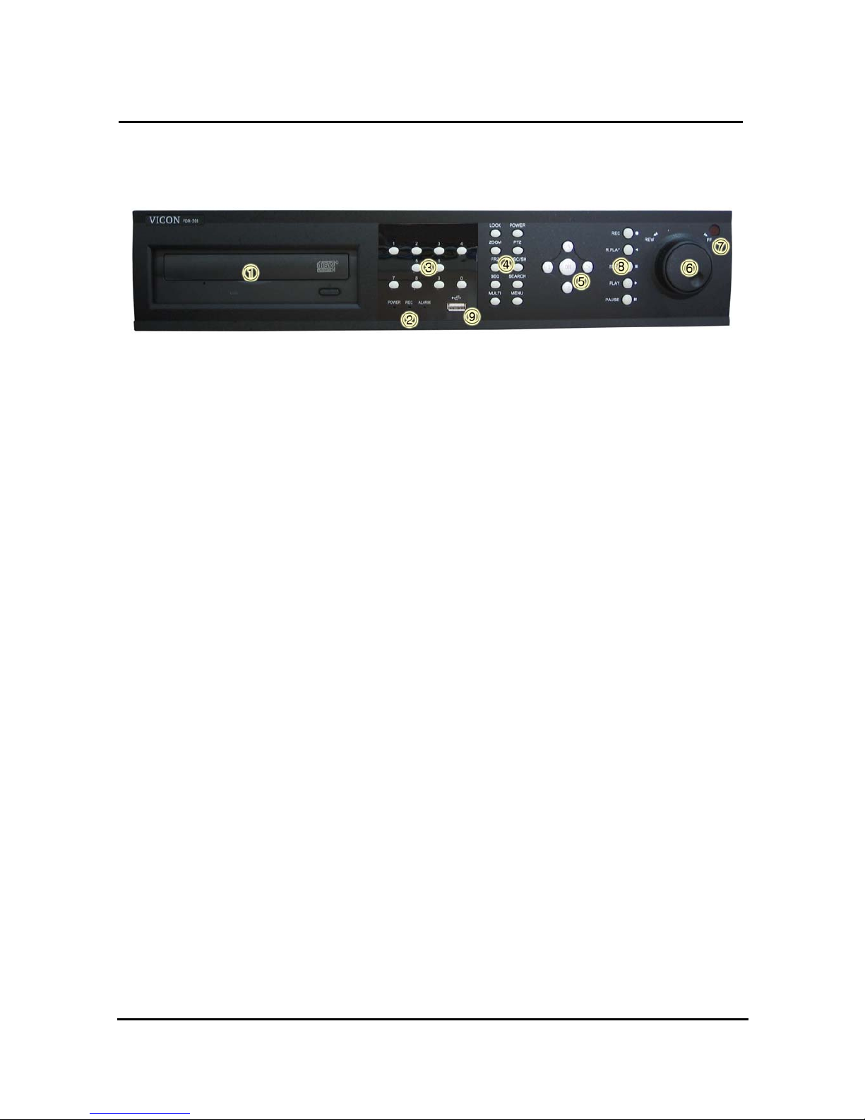
1.4.1 Front view
<8 Channel>
Description:
1. CD/RW
2. LED indicator
POWER: Power Off status is indicated by a Red light and ON status is indicated
by a Green light.
REC: Green light (Recording)
ALARM: Green light (Alarm triggered)
3. Numeric button - Live Viewing mode button
Channel selection for Live Viewing and Playback mode, Password inputting.
Page 19

16
4. Function button
POWER: Press this button to power ON/OFF
- Soft Power method is adapted. Therefore, If Power button is pressed,
user is asked to input Password, before Power off.
LOCK: Press this button to lock/unlock the buttons of DVR, in order to prevent the use by
Unapproved user.
- If the LOCK button is pressed, DVR is locked, and it’s unlocked by inputting correct
password
ZOOM: Zoom In/Out on the images during Live Viewing.
FRZ : Freeze.
- Press button once to freeze the frame at live mode. Press again to return.
- To take a still image capture at playback mode.
- Exchange of video input type : Press power button with FRZ button from NTSC to Pal
or PAL to NTSC.
MISC/SH: Miscellaneous functions or Shuttle Hold.
- MISC: To substitute for the buttons that are placed on the remote control but that are
not placed on the keypad (NET, OSD, Audio Mute, HDD, LOG).
(If the button is pressed, windows appear, and user can select lower menu one by one)
- SH: Press button while using the Shuttle to hold the speed.
SEARCH : Press once to open the menu to search for recorded files.
PTZ: Pan/Tilt/Zoom. Press once to access the Pan/Tilt/Zoom/Focus control mode.
Press again to exit.
MENU: Press button to access Main Menu. Press again to return.
MULT
- Selection of Screen Division for Live Viewing mode
(8 screen -> 9 screen -> 4 screen -> 4 screen -> 6 screen division, )
- In order to go back to previous mode, user is required to push “MULT” button,
after selecting a specific channel
SEQ : Sequential view.
- View all active channels sequentially.
Also, Release all sections for Motion Detection Zone
5. Direction/select button
UP: Used to move the cursor up; change possible values in the setup menu; under
PTZ control sub menu, used to move camera; or used to adjust focus.
DOWN: Used to move the cursor up; change possible values in the setup menu; under
PTZ control sub menu, used to move camera; or used to adjust focus.
Page 20

17
LEFT: Used to change possible values in the setup menu. Under PTZ control menu,
used to move the camera left or used to do Zoom Out; At playback mode, used to
decrease playback speed.
RIGHT: Used to change possible values in the setup menu. Under PTZ control menu,
used to move the camera left or used to do Zoom In; At playback mode, used to
increase playback speed.
OK: Used as a selection key. Under PTZ control menu, used to be interchanged P/T
mode with Z/F mode
6. Jog/Shuttle
Shuttle: Multi-speed forward/reverse playback. Under Network Setup sub menu,
used to input parameters fast.
Jog: Frame by frame search.
7. IR receiver
Remote control signal receiver
8. Recording/Playback buttons
RECORD: Press once to begin recording all active channels. Press again to end recording.
R-PLAY: Reverse Playback. Press to begin reverse playback. Under PTZ control menu,
used to decrease the speed of Pan, Tilt, Zoom, Focus.
STOP: Stop playback.
PLAY: Access to playback.
- Playback button will activate assigned starting position and Channel at playback setup of
menu.
- At pause mode, it will release pause mode.
- Under PTZ control menu, used to increase the speed of Pan, Tilt, Zoom, Focus.
PAUSE: Press to freeze the picture at playback mode..
9. USB connector in the front panel
* This connector is for USB Memory stick to back up the image
Page 21
18
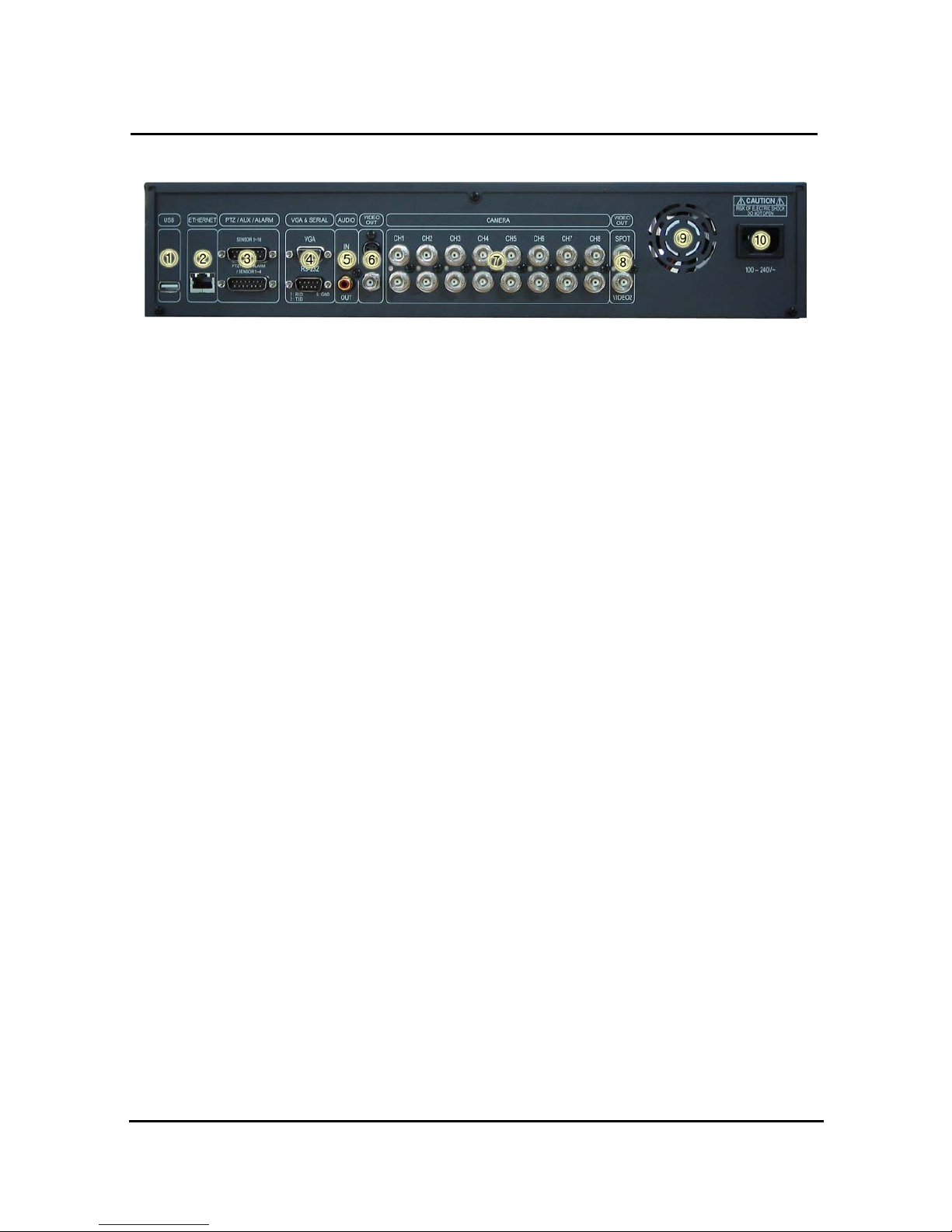
1.4.2 Rear panel view
Description:
1. USB
Connect USB flash drives for backing up stored video files.
2. ETHERNET
Network terminal for 10Base-T (RJ-45)
3. PTZ/AUX/ALARM
Terminal for PTZ, sensor, alarm, and AUX IN/OUT (DB-15 Male Connector)
4. VGA and SERIAL
VGA : Terminal for VGA video output (DB-15 Male Connector)
Serial terminal for RS-232C (PC) for console or quick installation (DB-9 Male Connector)
5. AUDIO
IN: Audio line input
OUT: Audio line output
6. VIDEO OUT
Terminals for composite video and s-video to connect with monitor
7. CAMERA
8 Inputs ( 1 ~ 8 ch) : With 8 loop through, the video of each channel can be out.
8. VIDEO OUT (SPOT and VIDEO 2)
SPOT : User can use this connector for a specific Spot Monitor
VIDEO 2 : With the Extra Output, user can connector with other monitor
( Same video image as Video 1)
9. FAN
Heat protection fan to reduce heat in the unit
10. POWER INPUT
Power cord terminal (free voltage, 100 - 240VAC, 50Hz/60Hz)
Page 22

19
1.4.3 Remote controller function
① POWER : button for power on/off. (DVR should be standby or on working)
② MUTE : button for voice off ( If it’s pressed again, voice on)
③ RECORD : button for forced recording (If it’s pressed again, recording stops)
④ INFO BUTTON GROUP : button group for HDD, NET, LOG, INFO.
If each button is pressed, the relative information shows and press Menu button for exit
⑤ NUMBER KEYPAD : use with OK button to select any channel
Ex : to select Ch 7, press 7 button and OK button.
Page 23

20
⑥ LOCK : Remocon Rock button. Same function as Lock button in the front panel.
To unlock, press any button and input password.
⑦ SEARCH : button to search data in HDD. Press the button to enter, and repress for exit
⑧ SEQ : button for sequence ( 2 functions)
- Press one time : one channel in full screen shows by interval.
- Press 2
nd
time : 4 division / 8 division/ 9 division screen shows.
- If press again, previous screen shows. To exit, press MULT button
⑨ MULT : button for division screen
- Basic screen : 8 ch. If it’s pressed each time, 8 screen -> 9 screen -> 4 screen
-> 4 screen -> 6 screen division shows
⑩ MENU : Button for menu. Various sub menu can be selected
- To exit, press again the button
⑪ Up/down, Right/left & OK button
Status OK Up/down Right/left
Menu Selection, sub menu Menu move x
Sub Menu Selection Move Menu Adjust value
Play x x Low speed and playback speed
Page 24
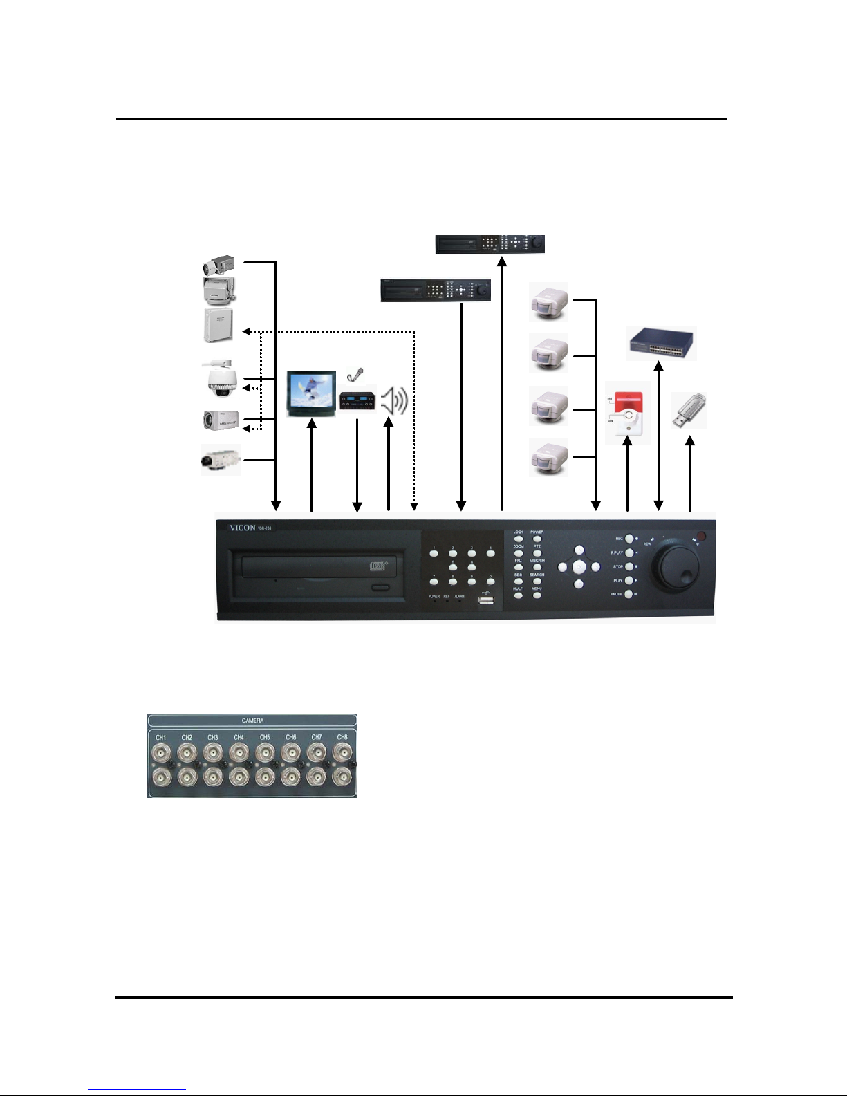
21
1.5 INSTALLATION
1.5.1 Installation and connection
Camera 1
Camera8
Camera 2
Monitor
Speak
Sensor 1
PTZ
Rec iever
Alarm
Network
USB
Sensor 16
~
Sensor 2
RS-485
AUX IN
AUX OUT
Mic
~
1.5.2 Camera
The unit comes with 8 video IN and 8 video OUT for up to 8
cameras connection
Page 25
22
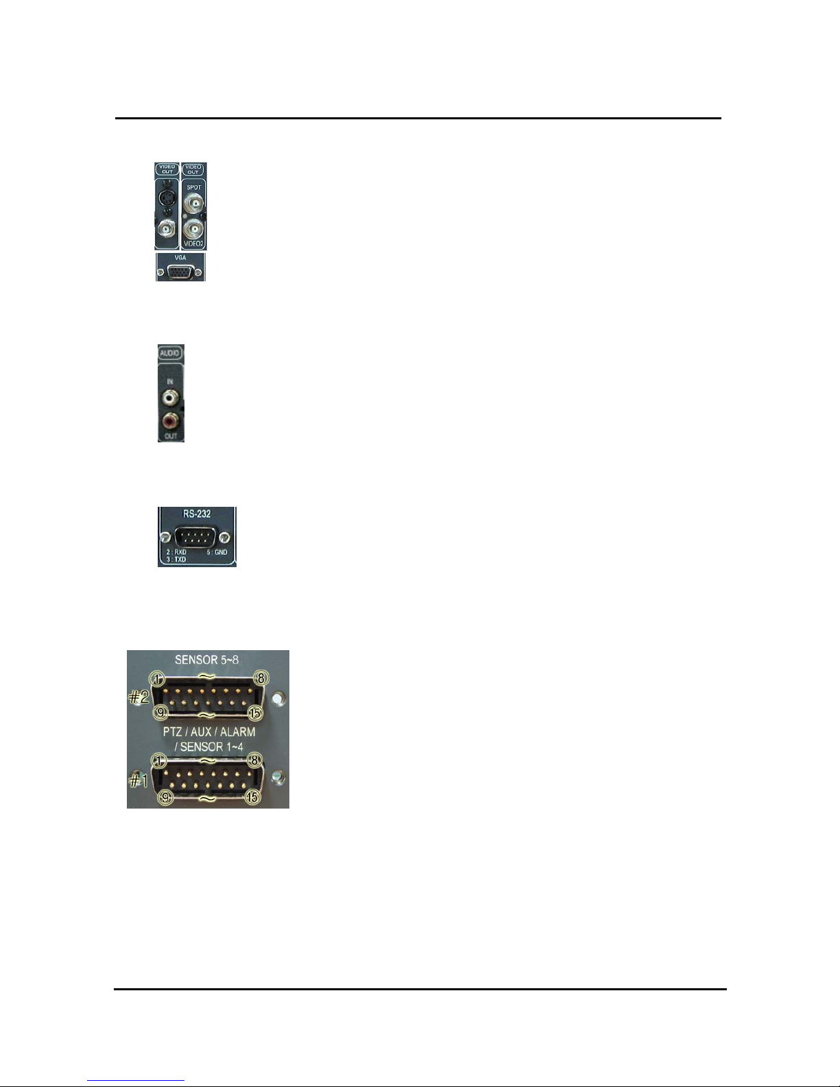
1.5.3 Video Out
The unit has two composite video outputs, one S-video output, one VGA output.
Also one spot output allows users to select specific channel for special monitoring.
1.5.4 Audio
Use IN for a Line input and OUT for speaker output.
1.5.5 RS-232
Use this connector to connect RS-232 cable to the serial port on your PC to
control the DVR or to perform Quick Installation.
1.5.6 PTZ/AUX/ALARM
1.5.6.1 RS-485+, RS-485-
DVR uses RS-485 protocol to control PTZ Receiver, Speed Dome, and
Auto-focus camera. Be sure to match the polarity.
1.5.6.2 AUX 1~5
AUX Port consists of 2 input ports (AUX 1,2) and 3 output ports (AUX
3,4,5) and the function of each port is selectable according to user’s
purpose, user’s access to external DVR, or controllers using the supplied DB-15 connector.
1.5.6.3 Alarm Out (NO, COM, NC)
The Alarm output is activated using a relay contact point when an alarm event occurs for the
duration of the alarm event.
Select from Normal Open Relay or Normal Close Relay.
N.O. (Normal Open) is disconnected from COM during normal status and connected to COM
Page 26
23
during alarm event. N.C (Normal Close) is connected from COM during normal status and
disconnected to COM during alarm event.
1.5.6.4 Sensor 1~8
Users can connect up to four N.O./N.C. type sensors and configure them within Main Menu,
Sensor Setting.
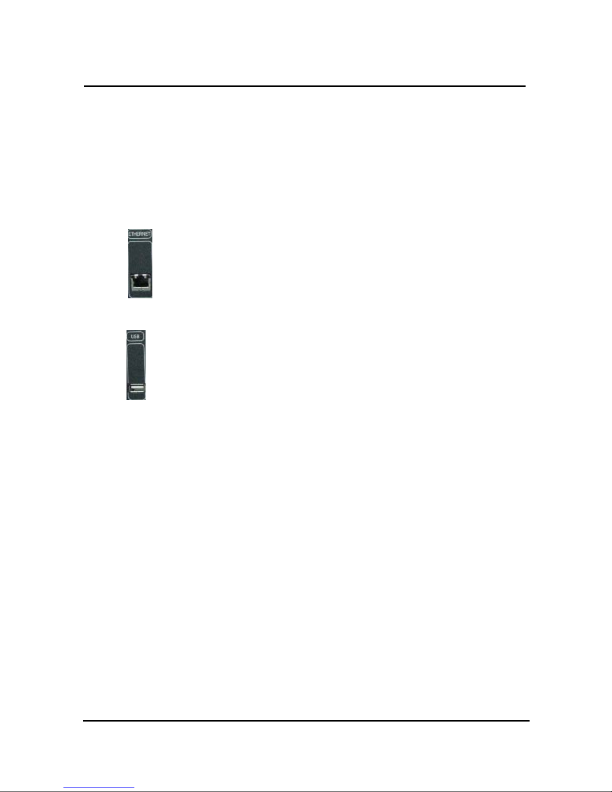
1.5.7 Network
Support 10 base- T Ethernet, and connect Ethernet cable.
1.5.8 USB flash memory
Perform backup of recorded video files from DVR system to USB flash memory
manually.
Page 27

24
2. Basic operation procedures
2.1 Power On/Off
2.1.1 Power ON
Using either the keypad or the remote control, press the “Power” button. (Note: In case of
power outage or rare instance of system failure, the DVR will reboot automatically)
The Power LED light will turn from red to green when it has turned on properly.
In a standby mode, the LED is red.
2.1.2 Power OFF
In order to shutdown the system, you must type in the password. The default password for
shutd ow n is “111111 ”.
2.2 Date & time setting
Set the date and time for the DVR.
(System Setup in Main Menu Time/Date)
2.3 Change of live video channel in Mux mode
Live channel can be changed in Mux screeen of DVR.
This function is available for 8 screen, 9 screen, 4 screen, 6 screen.
If OK key is pressed in the mux screen, box appears. Buttons are used to select the channel
And up/down key is used to move the channel.
After setting, if menu key is pressed, user can go back to Live picture.
2.4 Password setting procedure
Select or change your password for the DVR. The password must be a 6-digit number
consisting of numbers 0 ~ 8.
(System Setup in Main Menu System Password)
Page 28

25
2.5 Network setting
There are three types of network setting for the DVR: Static, DHCP, or PPPoE. Please set
the network type. (Network Setup in Main Menu)
2.6 Recording
Select recording related parameters in the Record Setup in the main menu.
2.6.1 Recording types
Enter in Recording setup of menu. For resolution, select either 640*240 (NTSC), 640*288 (PAL)
or 320*240 (NTSC), 320*288 (PAL). Audio channel is synchronized with the selected video
signal. Select Video input quality (Enhance/ Normal/ Fine/ Super fine), Frame rate (120 fps –
NTSC/ 100 fps –PAL), and recording mode. 8 channels can be selected at the same time,
2.6.2 Recording modes
Recording mode are made up of MANUAL, CONTINUOUS, MOTION, SENSOR,
MOTION+SENSOR, and SCHEDULE mode. A red record light ( ) on the top right corner of
each channel will indicate DVR recording.
In the MANUAL mode, the DVR starts to record on/off whenever the RECORD button is pressed.
Refer to the article 3.2.6 for details of Record mode.
2.7 Playback
2.7.1 Press the Play button
The DVR will playback either the first recorded file or the last recorded file according to the
setting in the Playback Setup menu.
2.7.2 Audio files
You will hear audio when video files containing audio is selected for playback.
2.8 Search
2.8.1 Search mode
The DVR has 2 types of search modes:
SEARCH BY TIME: Displays recorded data by recording time and camera number.
STILL IMAGE SEARCH: Displays recorded still images.
Page 29

26
2.8.2 Search method
When you press Search, select from three options listed: Search by Time, Still Image
Search, & Backup HDD Search. A detailed search list will open. Press OK button to view
the selected file.
Use the Left/Right key to move page by page. The Up/Down key is used to move between
items on the same page.
2.9 Backup
The DVR has various types of backup methods:
2.9.1 CD-RW
After inserting CD-Rom into CR-RW Drive, push Menu button & go to Backup menu, and
back up the moving picture of HDD by CD-RW for the selected time.
In the backup menu, select backup time
start backup, and backup for capacity of CD RW.
The backed-up files can be play-backed by Uniplayer
2.9.2 USB flash memory
User can backup manually from internal HDD to USB memory stick by connecting one to
USB port equipped at rear side of DVR
Connect USB Memory Stick into USB port Input the start of backup date and time at
backup menu Input the end of backup date and time at backup menu Select the
channel Select event condition.
USB flash memory will save backup to be used..
Backup by USB flash memory supports video data only.
User can replay backup files at proprietary UniPlayer client program.
2.10 Network
At remote sites, users will access to backup audio & video files recorded in local H.D.D to user’s
PC through network.
2.11 Client Program
2.11.1 RAMS (Remote Access & Monitoring System)
Remotely access, monitor, and operate the DVR for real-time live viewing, playback, backup,
on-the-fly recording, and control over the LAN/WAN
Page 30

27
Upgrade the S/W(Kernel, Ramdisk) of DVR
Install the RAMS program as referred to in section 4.2 of Operation Manual.
Execute RAMS program and register selected DVR’s IP address & Port number from the DVR
list.
After selecting the target DVR, enter “admin” for ID and “111111” for default password. This
will enable you to access the DVR.
2.11.2 UniPlayer
A viewer with functions for recording, capturing, & backing up files.
2.11.3 MultiViewer
To monitor multiple DVR, both locally and remotely.
2.11.4 Quick Installer
To setup configuration template for quick & easy, multiple unit setup using RS-232 or network
To upload/download DVR menu setting from/to DVR as file form using pc.
Page 31
28
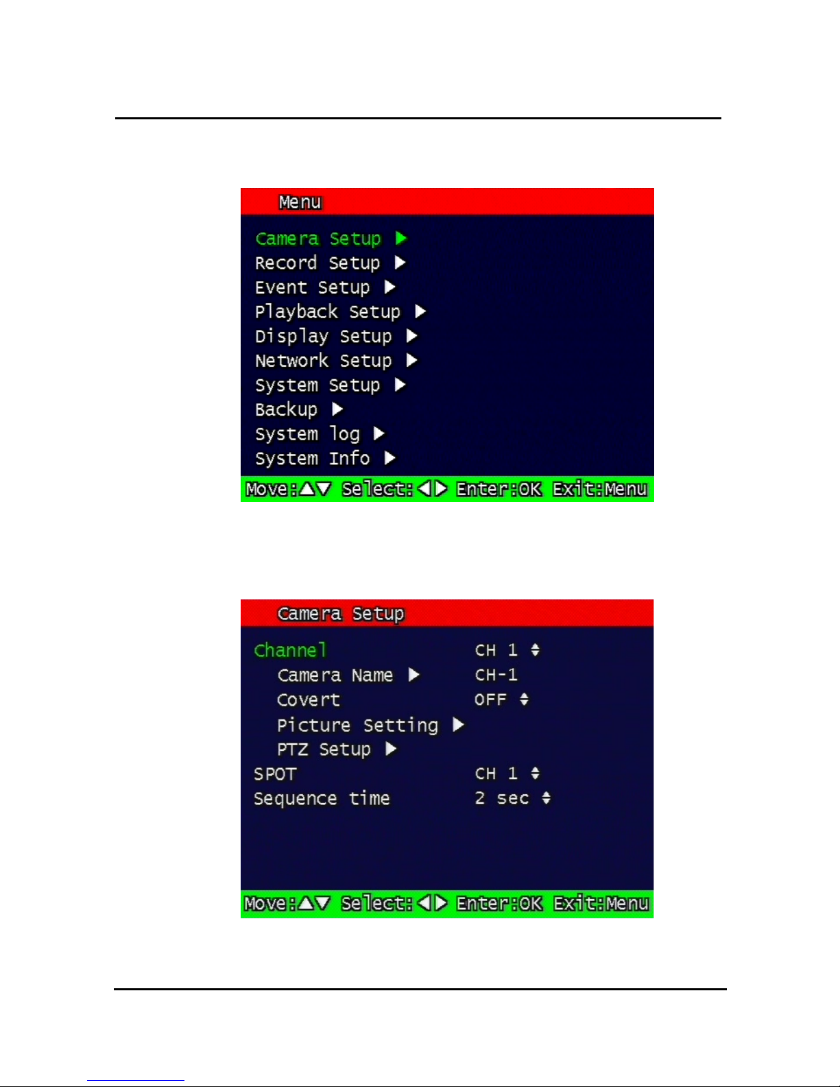
3. Main Setup screen
Figure. 3-1
Main Setup screen
3.1 Camera Setup menu
Figure. 3-2
Camera setup screen
Page 32
29
3.1.1 Channel number.
A user can select targeted camera. After setting, this, live viewing picture will be changed
to selected channel automatically.
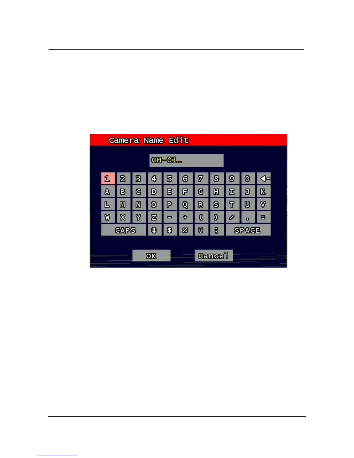
3.1.2 Camera Name Edit
Figure. 3-3
Camera name edit screen
User can edit camera name indicated button part of each channel. as explained paragraph
3.1.1. According to above picture 3-3, after keyboard type’s window which is enterable or
editable as displayed, user can set channel name with entering new letters and it is available
12 letters at maximum. Selected name at this paragraph will be displayed at the left side of
top portion on window.
By using “CAPS” button, user can shift a letter to capital one and/or inversion.
By using “◀ㅡ” button, user can delete miss-entered characters .
If you enter “OK” button, entered name will be applied after that and revert to previous menu.
If user enter “cancel” button, entered name will be discharged and maintain the present
name & reverted to prior menu.
Page 33
30
3.1.3 Camera hide
User can make the live screen appear or not by channel with this function.
If user sets up “On” in this function, the live screen of the selected channel does not appear.
In case of recording, the recording continues, although screen does not appear.
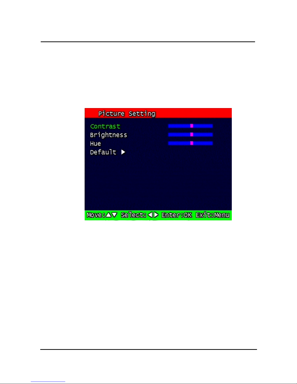
3.1.4 Picture Setting
Figure. 3-4
4 Picture setting screen
3.1.4.1 Contrast, Brightness, Hue,
Contrast, Brightness, Hue will be managed & each parameter has 16 level steps
adjustable.
3.1.4.2 Default
Users can restore the factory default setting of Contrast, Brightness & Hue.
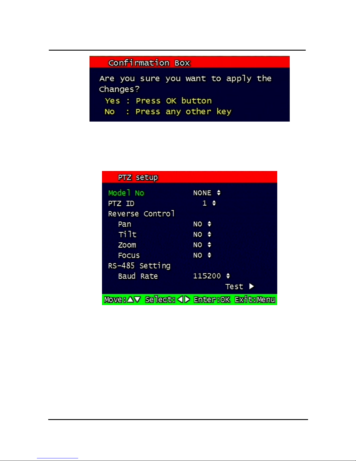
Confirmation box on picture setting default will appear after entering default. User can
restore the factory default setting after entering ‘yes’ key button.
Page 34
31
Figure. 3-5
Confirmation box on Picture Setting Default
3.1.5 PTZ setup
Figure. 3-6
PTZ setup screen
It sets PTZ protocol of targeted channel in the Camera Setup. (Please refer to paragraph
3.1.1 for channel selection)
3.1.5.1 Model Number
Select the PTZ model or choose “NONE”.
Page 35

32
3.1.5.2 PTZ ID
Set the PTZ ID: 0 ~ 255
The PTZ ID must match the ID number that has been set by the PTZ Controller. Please
verify the ID on the Controller first before setting the PTZ ID.
3.1.5.3 Reverse Control
Without any further changing of cable connection, user can control PTZ controller by
changing reverse direction of PTZ. Each PAN, TILT, ZOOM, FOCUS will be selectable to
reverse direction and each parameter will be selectable ON /OFF.
3.1.5.4 RS-485 Setting
Choose from the following to set PTZ RS-485 baud rate: 2400, 4800, 9600, 19200, 38400,
57600, 115200 bps.
3.1.5.5 TEST
Users can test the PTZ control after setting the parameters. After clicking the TEST button,
PTZ control will be available and tested by up/down key. Pan/tilt and Zoom/Focus mode will
be controlled after entering OK key button.
PTZ control speed will be controlled by PLAY button for higher speed or by R-PLAY button
for precision control
Users can access prior menu with PTZ key entering after finishing test.
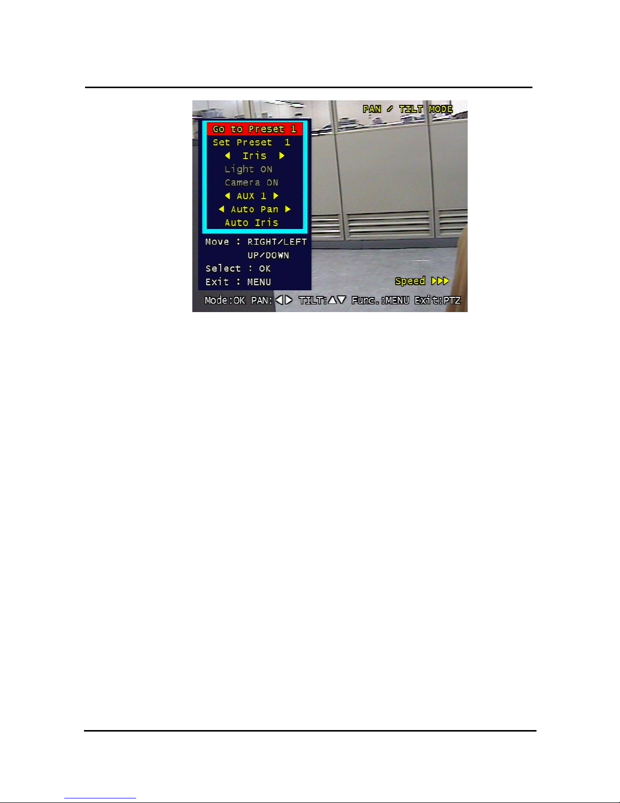
3.1.5.6 Additional PTZ Menus
Users can access additional PTZ menu after pressing Menu button in the PTZ mode.
Page 36
33
Figure. 3-7
Additional PTZ Menu
- Go to Preset : To move the Pan/Tilt drive to the position preset in Set Preset mode.
Preset numbers are selected by Left/Right buttons and the Pan/Tilt drive
moves to the preset position after pressing OK button.
- Set Preset : To preset the position of the Pan/Tilt drive. Users can preset 99 positions
selected by Left/Right buttons and save the preset by pressing OK button.
- Light : To turn on/off the camera lighting selected by Left/Right and OK buttons.
- Camera : To turn on/off the camera itself selected by Left/Right and OK buttons.
- Aux : To turn on/off the AUX (six) connected to the camera. On/off are selected
by Left/Right and OK buttons.
- Auto Pan : To automatically pan the camera. Pan speed are selected by Left/Right and
OK buttons.
- Auto Iris : To automatically Iris the camera.
3.1.5.7 Accessing SurveyorVFT Setup Menus
To get access an SurveyorVFT set up menu, do the following:
Make sure a Vicon PTZ set up has been saved for at least one camera input.
Press the PTZ button on the front panel of the VDR.
You now have to access the "functions" menu by pressing the Menu button on the VDR.
This displays the Go To Preset option and A/I, A/P, etc.
Page 37
34
Go to preset 94 and select A/P. Refer to the SurveyorVFT Programming Manual XX134-4X
for specific instructions.
3.1.6 Sequence time
It can set sequential display time of each channel during Live Viewing mode.
Choose from 2, 4, 5, 8, 10, 15, 30 second sequential display time.
3.2 Record Setup menu
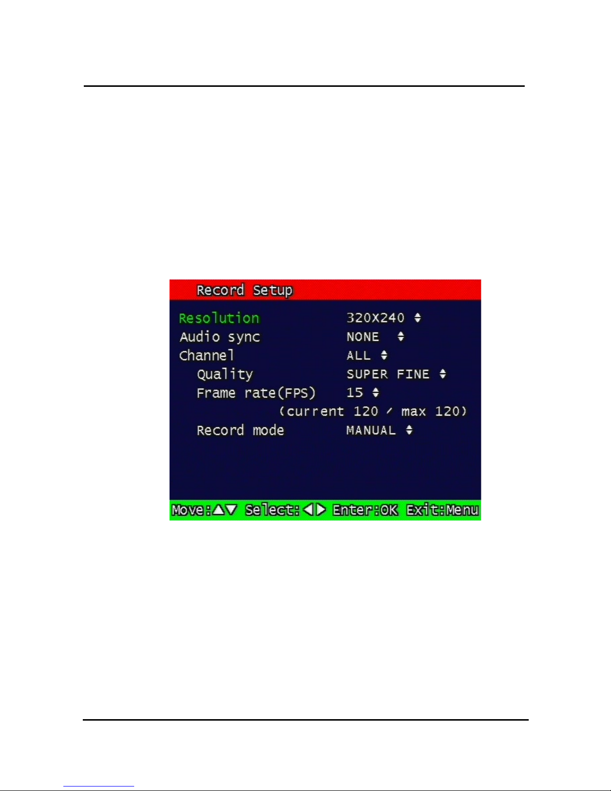
Figure. 0-1
Record setup screen
3.2.1 Resolution
Resolution for NTSC is “320 x 240” or “640 x 240”. PAL is “320 x 288” or “640 x
288” selectable and selected resolution will be applicable to all channels
simultaneously.
3.2.2 Audio Sync
As audio input port is one channel available, user should synchronize audio signal with
targeted video signal. With synchronized channel will record audio as well as video. But
others will only record video input signal only.
Page 38

35
3.2.3 Channel number
Quality, frame rate, record conditions will be selected per channel. So users can choose
targeted channel. All means all of channels.
3.2.4 Quality
Recording quality of each channel will be selectable & Normal, Enhanced, Fine, Super Fine
4 steps are available now.
3.2.5 Frame rate
User select channel’s recording frame rate and none (no recording), 1, 2, 3, 4, 5, 6, 7, 8, 9,
10, 15, 20, 30 fps will be available. The total for all the cannels is max 120 fps.
But, with 640 x 240 (NTSC), 640x288 (PAL) resolution, user should not set to exceed 60
frame per second with accumulated total channel recording.
3.2.6 Record mode
User will choose recording mode channel by channel and selectable parameters and
meaning are below.
• Manual: Manual recording function that starts record and/or stop recording
manually by pushing REC key on remote controller or on front key.
• Continuous: Continuous recording mode that starts to recording automatically after
turning on the systems.
• Motion: Start to record under motion detection. Under Motion, it starts pre-
alarm recording around 2 or 3 second and maintains it until no of motion event. Post-
alarm recording will be controlled at Post alarm recording time on Event Setup Menu.
(Refer to paragraph 3.3.4)
• Sensor: Start to record under sensor input. As same as motion mode, it starts
pre alarm recording around 2 or 3 second and maintain it until no of sensor input. Post-
alarm recording will be controlled at Post alarm recording time on Event Setup Menu.
(Refer to paragraph 3.3.4)
• Motion + Sensor: Start to recording under motion detection or Sensor
occurrence. The detailed will be referred to previous motion detection & sensor
occurrence.
• Schedule: This mode supply user defined time and date schedule
recording in advance detailed recording schedule will be referred to paragraph 3.2.7
record schedule.
Page 39
36
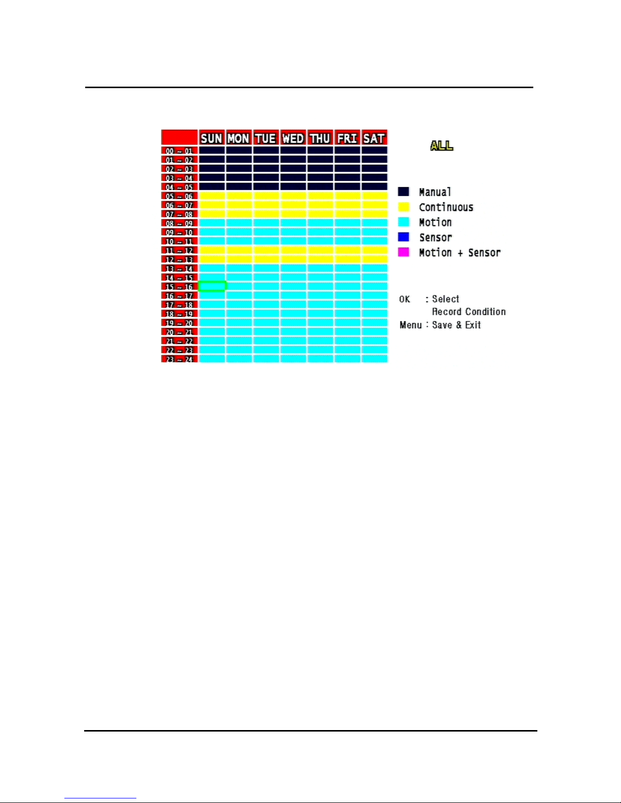
3.2.7 Record Schedule Setup
Figure. 0-2
Recording schedule setting screen
User can select to set recording schedule targeted date, time based week & 24Hours.
Move the cursor to the desired position of time by pressing up/down key and set the
recording mode at the desired position of time by pressing the OK button with referring to the
Help Message per Record Mode on the right position. After the setup, store the set schedule
and exit to the top menu by pressing the Menu button.
Page 40
37
3.3 Event Setup Menu
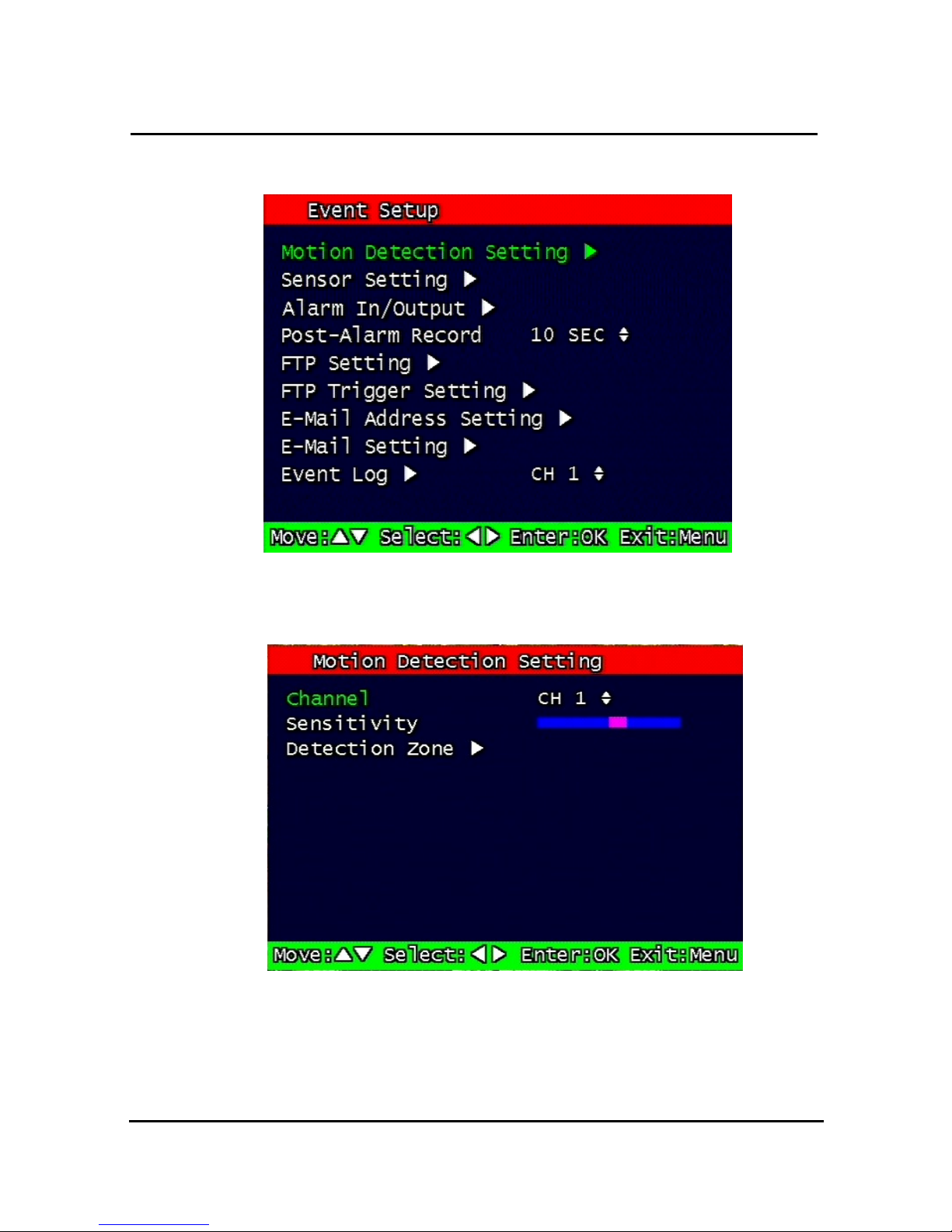
Figure. 0-3
Event Setup screen
3.3.1 Motion Detection Setting
Figure. 0-4
Motion Detecting Setup screen
Sets up the motion detecting area and sensitivity.
Page 41
38
3.3.1.1 Channel
Sets up the motion detecting area and sensitivity for each channel.
3.3.1.2 Sensitivity
Sets up the motion detecting sensitivity. The lower the sensitivity gets the closer to the left
the red bar gets.
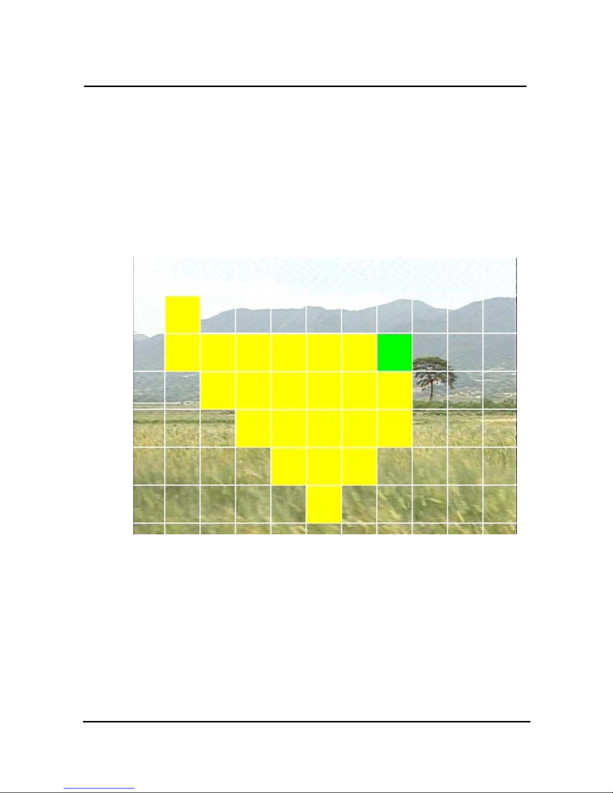
3.3.1.3 Detection Zone
Figure. 0-5
Motion Detecting Area Setup screen
Selects the motion detecting area. The sky blue square implies the current cursor and the
yellow square implies the area that was already selected as the motion detecting area.
When the cursor positions on the area that was selected as the motion detecting area, it
turns green. Above screen is for MUX motion detection set-up.
Full screen shall be as the motion detecting areas after entering MULTI button. The reverse
key button is SEQ erasing motion detecting area.
Page 42
39
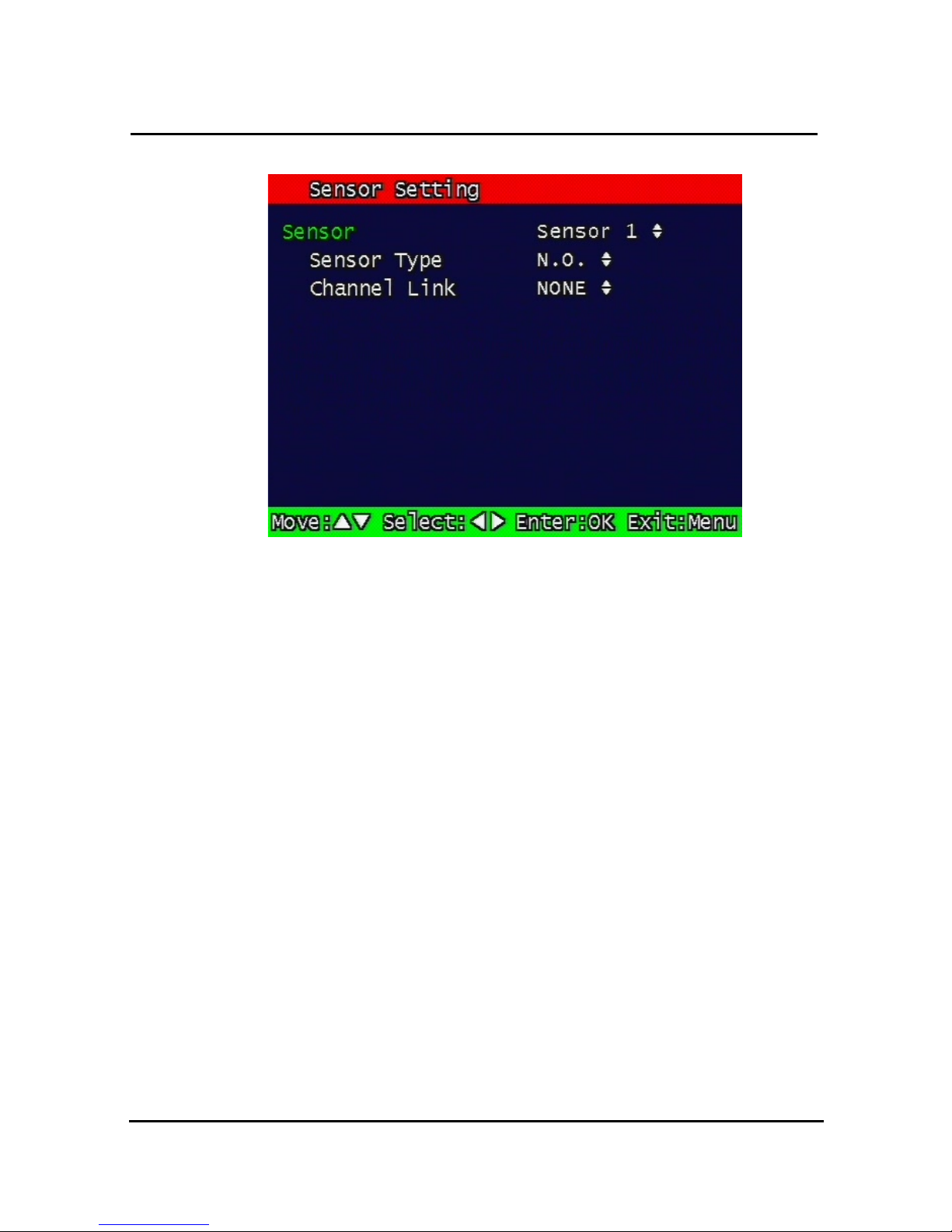
3.3.2 Sensor Setting
Figure. 0-6
Sensor Setting screen
3.3.2.1 Sensor Type
N.O.: Normal Open. Operation mode for the installed sensor’s contact point is usually open
in normal condition and changed from open to close at sensor’s detect event.
N.C.: Normal Close. Operation mode for the installed sensor’s contact point is usually close
in normal condition and changed from close to open at sensor’s detect event.
•
3.3.2.2 Channel Link
Assign sensors to designated Camera Channels.
Page 43
40
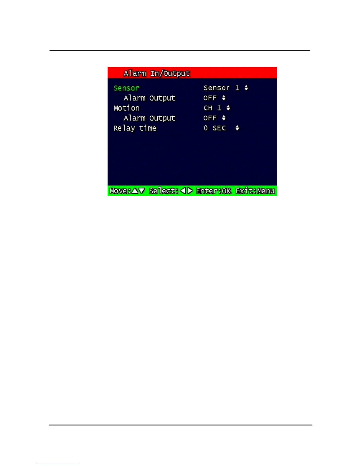
3.3.3 Alarm Output
Figure. 0-7 Alarm Output Setting
3.3.3.1 Sensor
Configure the alarm out on/off activated by the sensor.
3.3.3.2 Motion
Configure the alarm out on/off triggered by the motion detection.
3.3.3.3 Relay Time
Configure the alarm duration time. It can be set up from 1 second to 60 seconds in the unit of
5 seconds.
3.3.4 Post Alarm Record Time
Configure the recording continuation time after starting an event recording. It can be set up
from 10 seconds to 60 seconds in the unit of 10 seconds.
Page 44
41
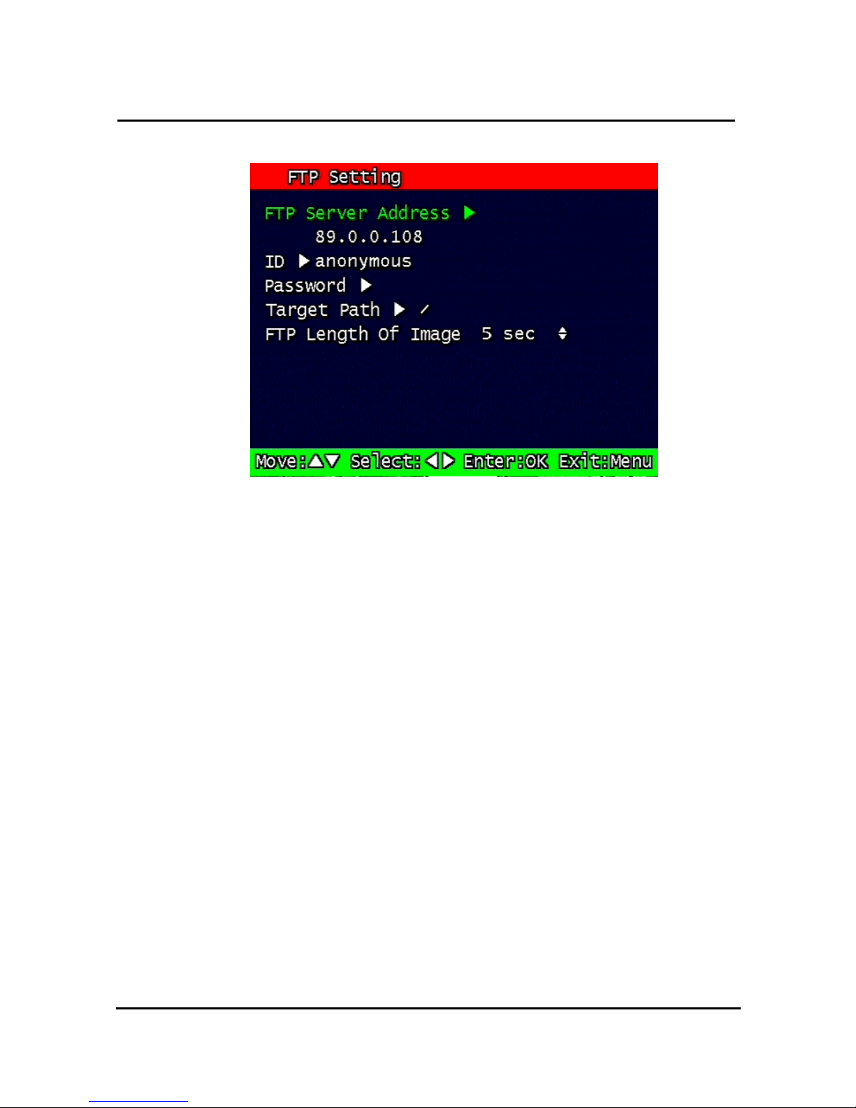
3.3.5 FTP Setting
Figure. 0-8 FTP Setting
Enables the unit to transmit an assigned FTP Length of Motion picture to an FTP Server over
network when an event occurs. The event will be transmitted 15 seconds after the event
occurs.
3.3.5.1 FTP Server IP address
Configure the IP address of the FTP server. The number changes by moving left and right,
and then it moves to the next digit by pressing the OK button for setting up the next number.
Change the IP address of the FTP server to fast forward or backward by using
shuttle equipped in front panel.
Page 45
42
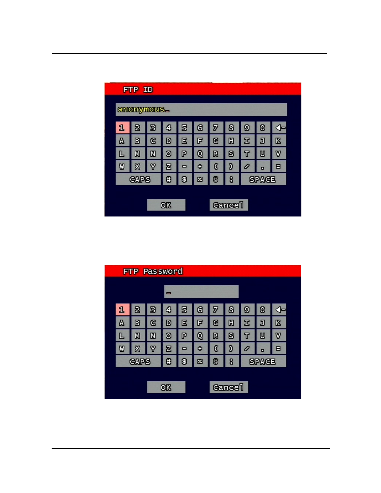
3.3.5.2 ID
Configure the FTP ID. The ID can contain maximum of 31 characters.
Figure. 0-9 FTP ID
3.3.5.3 Password
Configure the FTP password. The password can contain maximum of 12 characters.
Figure. 0-10
FTP Password input
Page 46
43
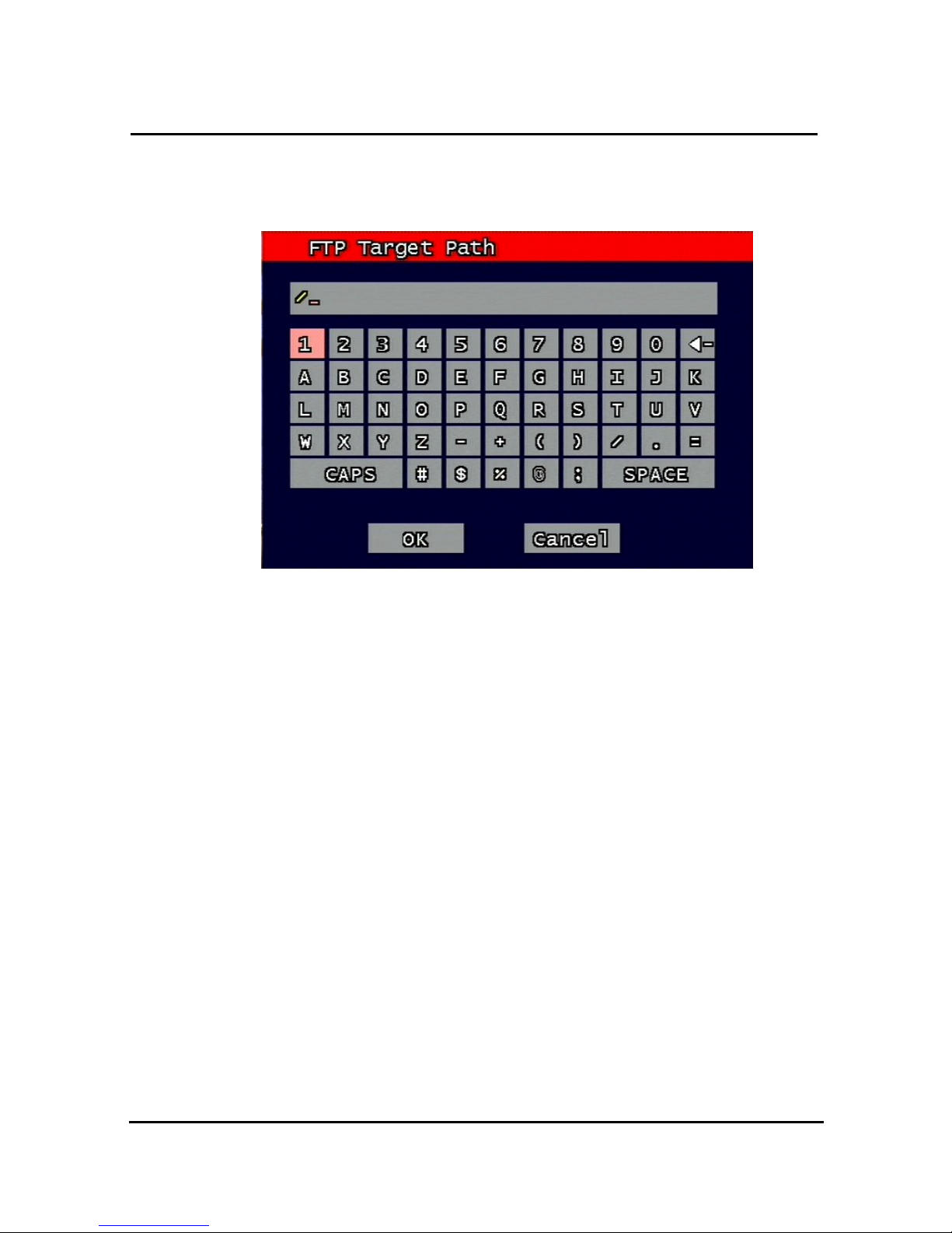
3.3.5.4 Target Path
Configure the path to transmit to an FTP server. The path can contain maximum of 31
characters.
Figure. 0-11 FTP Target Path
3.3.5.5 FTP Length of Image (second)
Select FTP length of image by second (5 to 10 seconds are selectable)
to transmit image files for selected seconds.
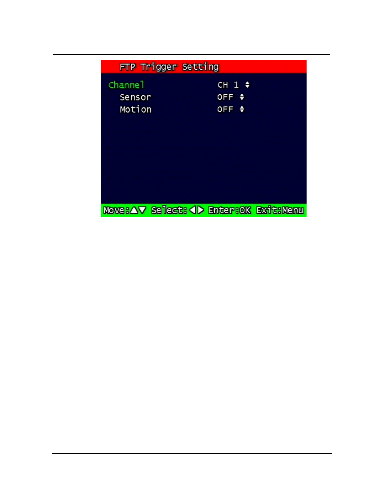
3.3.6 FTP Trigger Setting
Selects on/off for transmitting the video file to FTP for each channel.
Page 47
44
Figure. 0-12
FTP Trigger Setting
3.3.6.1 Sensor
Configure sensor events.
3.3.6.2 Motion
Configure motion events.
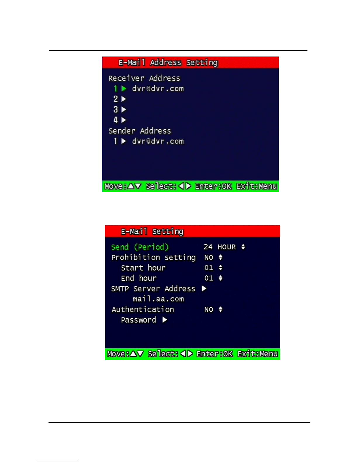
3.3.7 E-Mail Address Setting
Transmits the content of an event log periodically through e-mail. Configure up to four e-mail
address to transmit under event status simultaneously. The e-mail address can contain
maximum of 31 characters, and the event logs transmitted through e-mail will be deleted in
the DVR unit.
Page 48
45
Figure. 0-13 E-Mail Address setting
3.3.8 E-Mail Setting
Figure. 0-14
E-Mail Setting
3.3.8.1 Send (Period)
Configure the e-mail transmitting cycle. It does not transmit when it is set to NO. The setting
time can be set up at the units of within 2 minutes after event, 30minutes, 1, 2, 5, 12, 24
Page 49

46
hours.
3.3.8.2 Prohibition setting
Set up prohibition time to transmit the e-mail. Users can enter prohibition time from
the starting time and the ending time of transmitting the e-mail
3.3.8.3 SMTP Server IP address
Configure the IP address of the SMTP server to transmit the e-mail.
If you do not know your SMTP server IP address then go to Command Prompt in
Windows, then use ping and SMTP name address eg smtp.yahoo.com as below to
get your SMTP IP address. (Same method also applies to finding FTP server IP
address from FTP name address).
3.3.8.4 Authentication
Users can select authentication process dependent on SMTP server requirement.
Selects on/off for authentication process do authentication process whenever
transmitting e-mail messages through SMTP server.
3.3.8.5 Password
Enter sender’s mail password for authentication
C:\>ping smtp.yahoo.com
Pinging smarthost.yahoo.com [216.109.112.27] with 32 bytes of data:
Reply from 216.109.112.27: bytes=32 time=230ms TTL=50
Reply from 216.109.112.27: bytes=32 time=235ms TTL=50
Reply from 216.109.112.27: bytes=32 time=236ms TTL=50
Reply from 216.109.112.27: bytes=32 time=232ms TTL=50
Ping statistics for 216.109.112.27:
Packets: Sent = 4, Received = 4, Lost = 0 (0% loss),
Approximate round trip times in milli-seconds:
Minimum = 230ms, Maximum = 236ms, Average = 233ms
Page 50
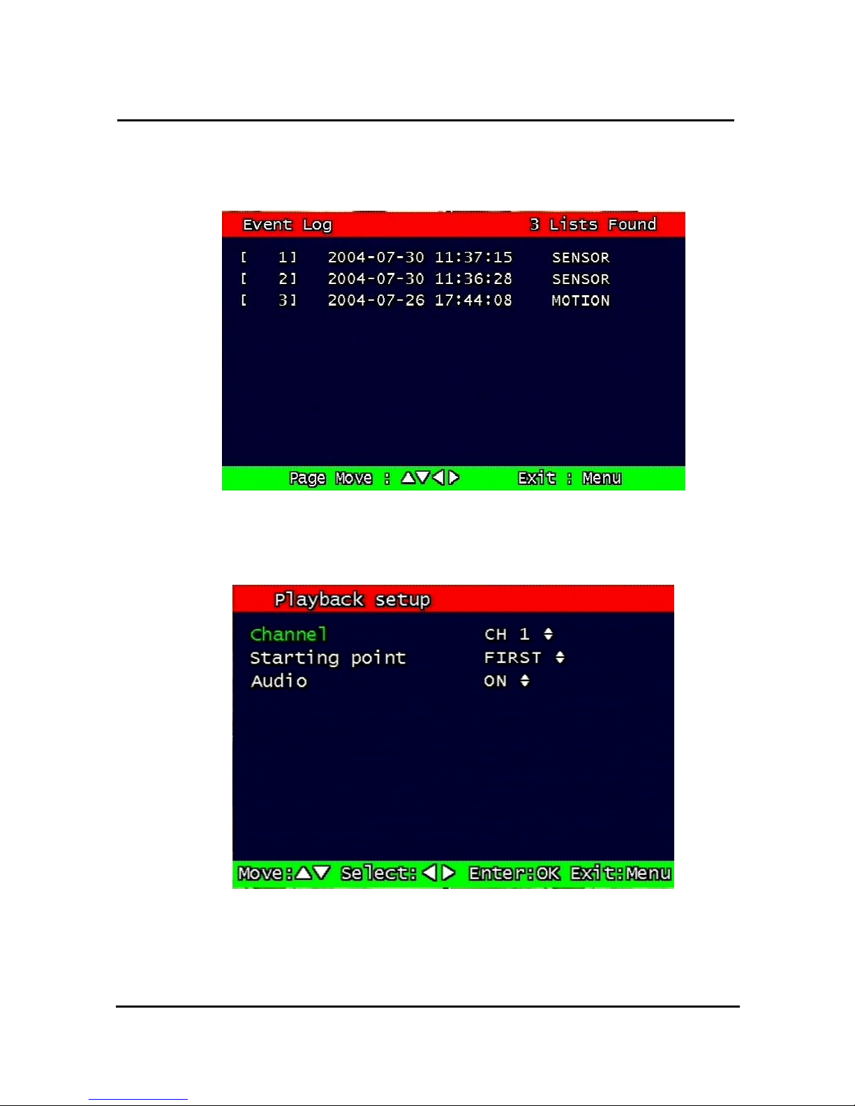
47
3.3.8.6 Event Log
Shows the event log of the selected channel. It can reset periodically by setting e-mail as
described in paragraph 3.3.7.
Figure. 0-15
Event Log Display screen
3.4 Playback Setup
Figure. 0-16
Playback setup screen
3.4.1 Channel
Designate the channel to be viewed when the “Replay” button is pressed.
Page 51
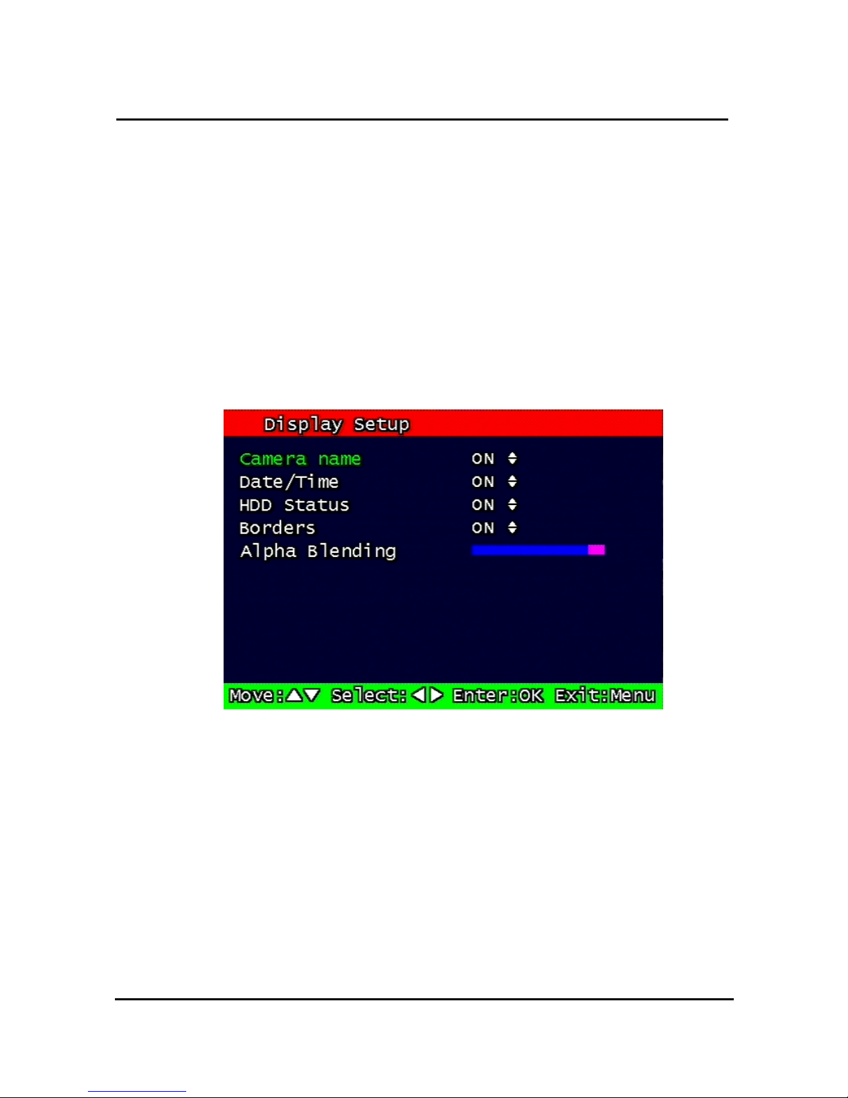
48
3.4.2 Starting Point
This starting point configures the starting position when the “Replay” button is pressed.
FIRST: This can search for and replay the oldest recorded images from the selected
channel.
LAST: This can search for and replay the latest recorded images from the selected channel.
3.4.3 Audio
If the recorded files contain audio, choose whether to turn the sound ON/OFF when the
“Play” button is pressed.
3.5 Display Setup
Figure. 0-17
Display setup screen
Determine whether to have the following be shown on the monitor: Camera name,
Time/Date, HDD status, Borders (Multi View). Select either ON/OFF for each item.
Page 52
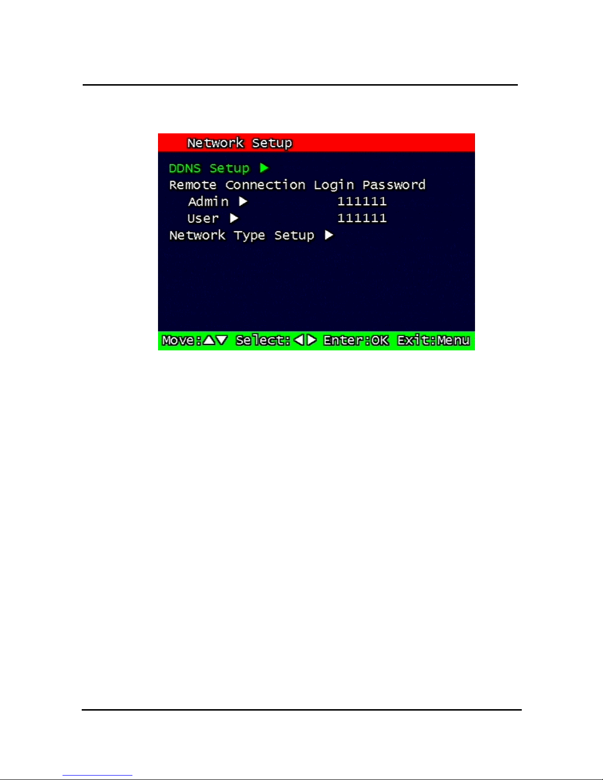
49
3.6 Network Setup
Figure. 0-18 Network Setup screen
3.6.1 DDNS setting
Set up DDNS (Dynamic Domain Name System) server address & port number.
Users can set up two DDNS server address and port.
Page 53
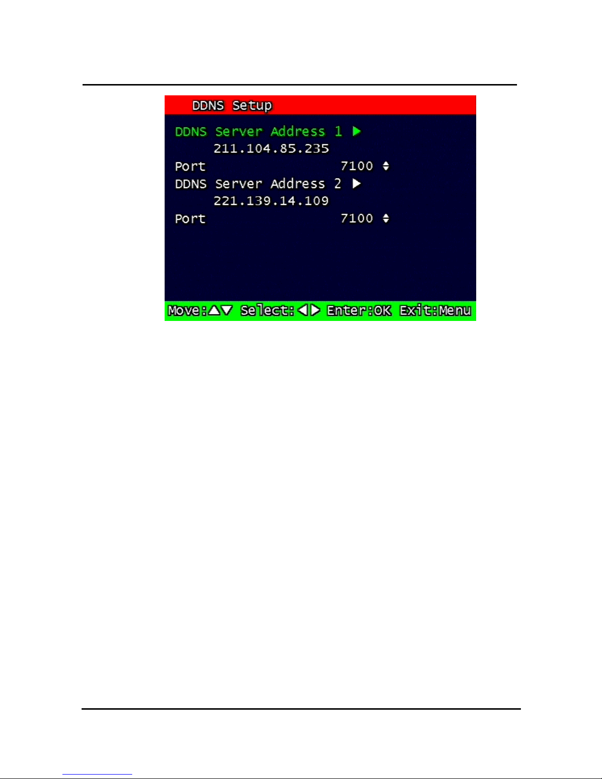
50
Figure. 0-19 DDNS setup screen
Under DHCP or PPPoE configuration using IP Router, the DVR will receive an IP address
periodically, and each time, the IP address can be different. Therefore, in order for users to
access the DVR over the network, it must update its IP address to the DDNS Server.
Under IP router configuration, IP of DVR must be setup as static IP address and it must
update its IP address to the DDNS server. Therefore DDNS Link on NETWORK SETUP
menu should be on. (When IP router is connected from static IP, it is no necessary to setup
DDNS link on)
By indicating the address of a DDNS Server, the DVR will update its IP address and its MAC
address periodically. Therefore, when users access the DVR over the network, the same
URL can be used. For example, if the DVR has a MAC address of “00:09:F8:12:34:56” and
the domain name of the DDNS server is “ns.udrdns.net ”, the users can access the DVR with
the URL “u123456.udrdns.net” The DDNS will know which machine to resolve the URL
because it would contain an updated IP address and MAC address list.
The factory default value of the DDNS server address is as follows:
DDNS address: 211.104.85.235
DDNS connection port: 7100
If users wish to operate the DDNS server by themselves, please contact us.
Page 54
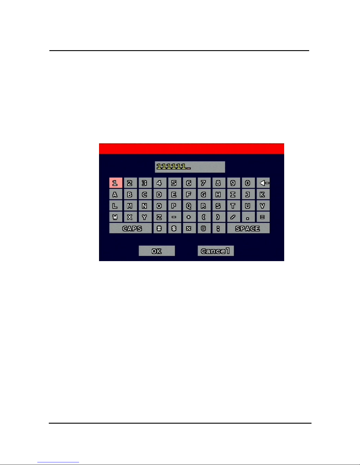
51
3.6.2 Remote Connection Login Password
There are two levels of access that can be set up in the RAMS program.
- Admin (Highest), User (Normal)
- By default, the password is 111111 when the software is first installed.
Users can use any numeric number from 0~4, combined 6 units.
Figure. 0-20 Remote Connection Login Password screen
3.6.3 Network Type
Choose one type from the following: Static, DHCP, & PPPoE.
Static mode uses fixed assigned IP address in the network.
DHCP (Dynamic Host Configuration Protocol) receives an IP address from the DHCP Server,
and it may change according to the lease period.
PPPoE (PPP over Ethernet) mode is used for network using PSTN such as ADSL.
Please refer to paragraph 3.6.3.1, 3.6.3.2, 3.6.3.3 for detailed network type setup process
Page 55
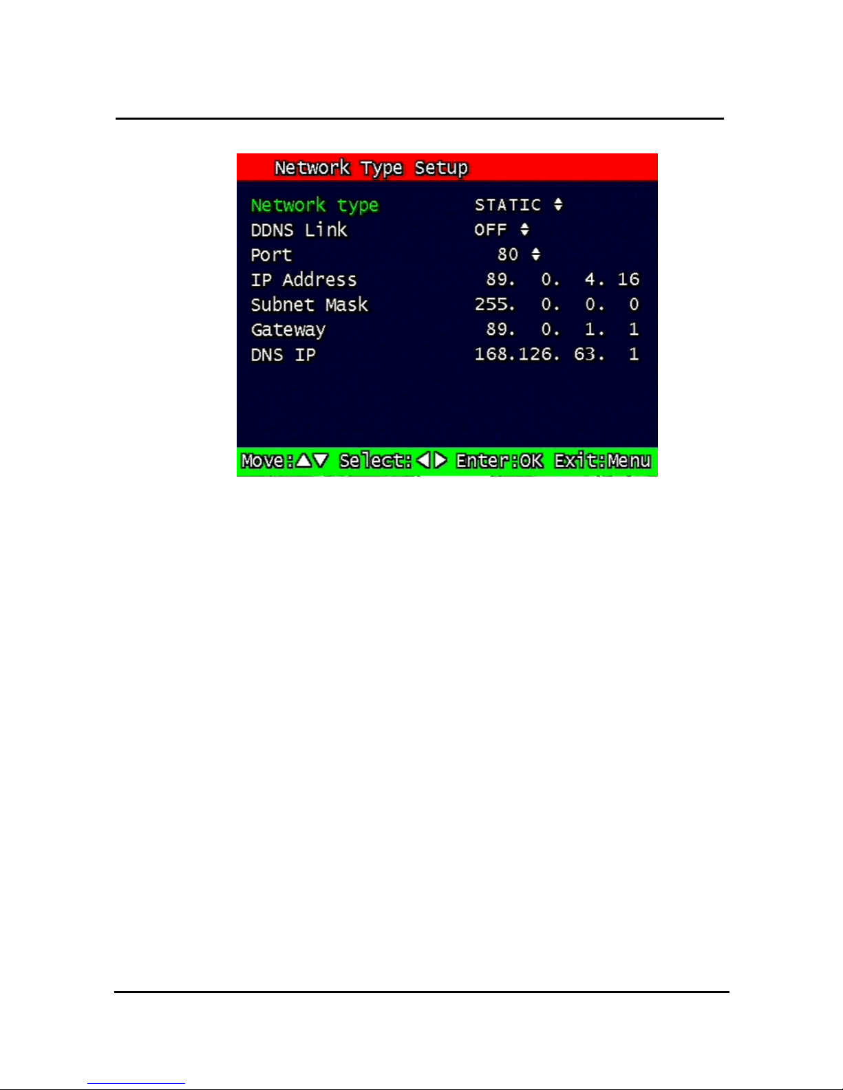
52
3.6.3.1 Static
Figure. 0-21
Static Network setting
1. DDNS Link On/off
2. Port
Configure the Port number to be used to connect to the DVR system using RAMS (Remote
Access & Monitoring System). The default Port number is port 80. Change easily by using
Jog/shuttle equipped in front panel.
3. IP Address
Assign a fixed IP address to the DVR. Change easily by using Jog/shuttle equipped in front
panel.
4. Subnet Mask
Assign the Subnet Mask. Change easily by using Jog/shuttle equipped in front panel.
5. Gateway
Assign the Gateway address
Change easily by using Jog/shuttle equipped in front panel.
Page 56
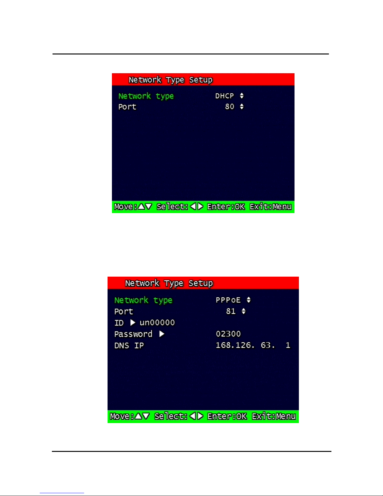
53
3.6.3.2 DHCP
Figure. 0-22
DHCP setup scre
1. Port
Please refer to paragraph 3.6.3.1 for Port setting of Static/ DHCP/ PPPoE)
3.6.3.3 PPPoE
Figure. 0-23 PPPoE setting
Page 57
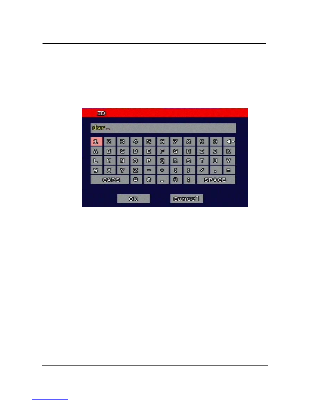
54
1. Port
Please refer to the port setting in paragraph 3.6.3.1
2. ID
Type in your user ID for the ADSL account (PPPoE).
The password can contain maximum of 31 characters.
Figure. 0-24 ID input screen
3. Password
Type in your user Password for the ADSL account (PPPoE),
The password can contain maximum of 12 characters.
Page 58
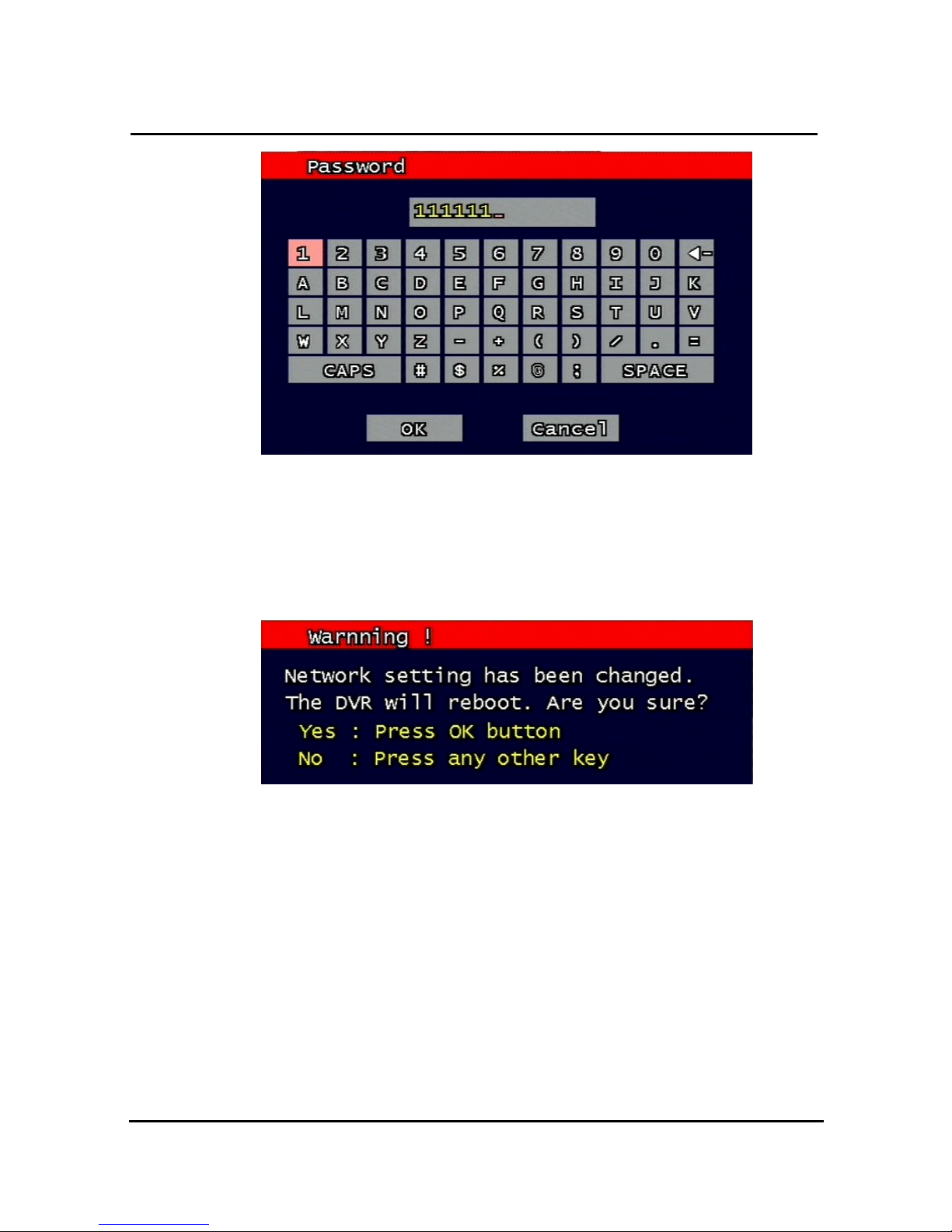
55
Figure. 0-25 Password input screen
3.6.4 Changing the Network configuration
If users want to change network type of DVR, users must reboot the system. User can
restart the new network mode setting after entering ‘yes’ key button.
Figure. 0-26 Changing the Network setting screen
Page 59
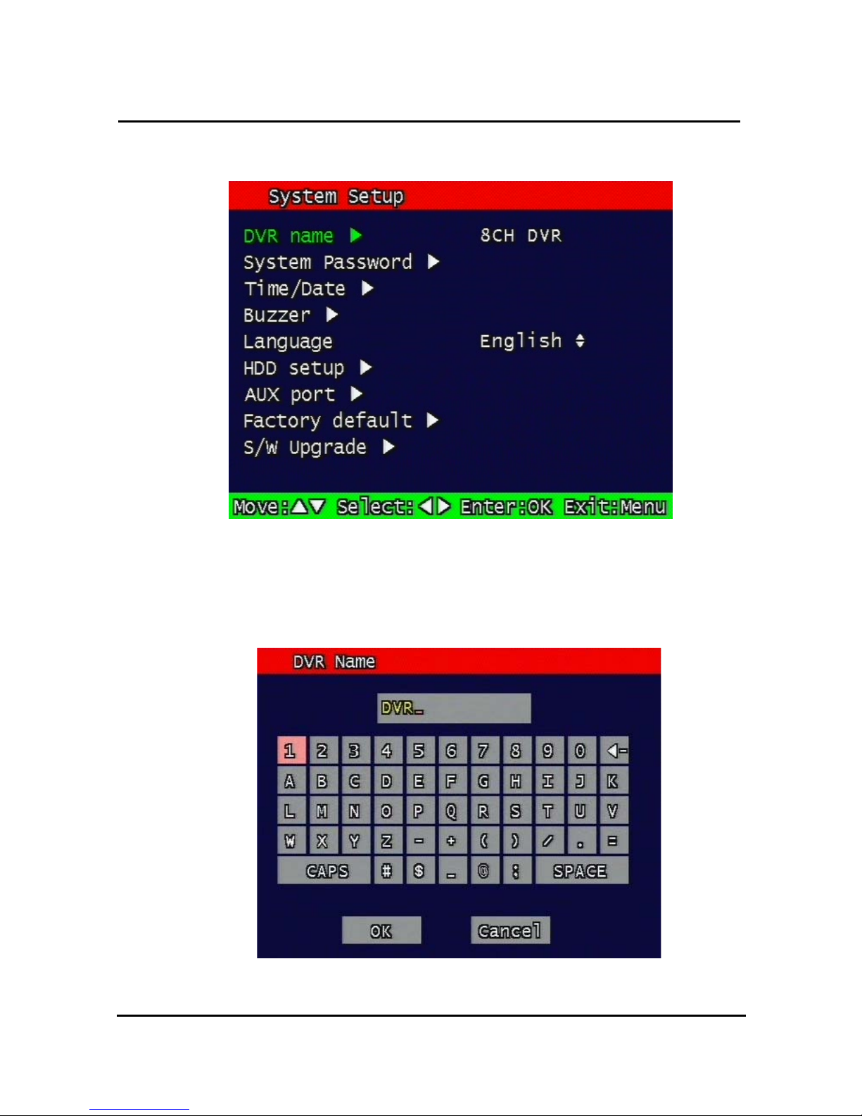
56
3.7 System Setup screen
Figure. 0-27
System Setup screen
3.7.1 DVR Name
Type in the name of the DVR you wish to assign. The name can contain maximum of 12
digits.
Figure. 0-28
DVR name screen
Page 60
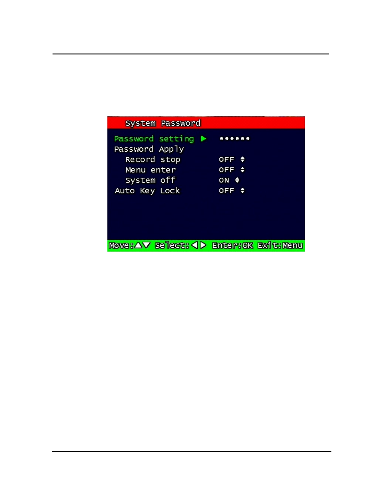
57
Using the arrow, type in the DVR name.
Click “OK” when finished.
3.7.2 System Password
Figure. 0-29
System password set up
Set up part for system password, related function and application.
This is a part of installation, actual system password, related function and password
application.
3.7.2.1 Password Setting
To change system password:
First, type-in the current password, confirm. Then if it is correct, type-in the new password
twice. If they match, the password has been changed.
Users can use any numeric number from 0~8, combined 6 units.
Password input screen (present, new, confirm, if it is wrong -twice, confirm to change)
Page 61
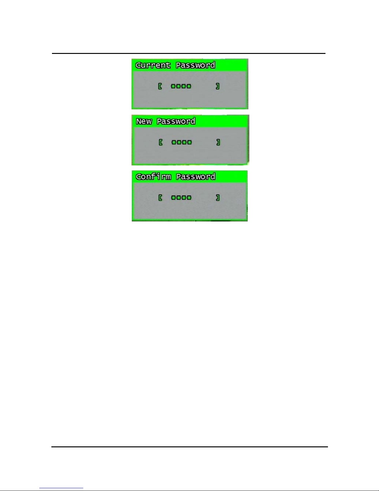
58
Figure. 0-30 Password input screen
3.7.2.2 Password Apply
Determine whether the system password has to be applied to power On/Off. The applicable
features are recording close, enter menu, system off. Users can set up password ON/OFF
for each feature.
Setting to On, when each feature starts, users have to confirm password for each step.
Setting to Off, users can use any confirmation of password.
3.7.3 Auto Key Lock
Possible Setting time is every 30sec, 1 min, 3min, 5min, 10 minutes. If users choose setting
time among them, auto key lock function will start exactly after the setting time and lock key
type icon will be displayed at the bottom of window.
Users can access system operation
after release from key lock state by entering right current password..
3.7.4 Time / Date
Users can configure the view of time & date on the system, as well as, Day Light Saving
Time.
Page 62
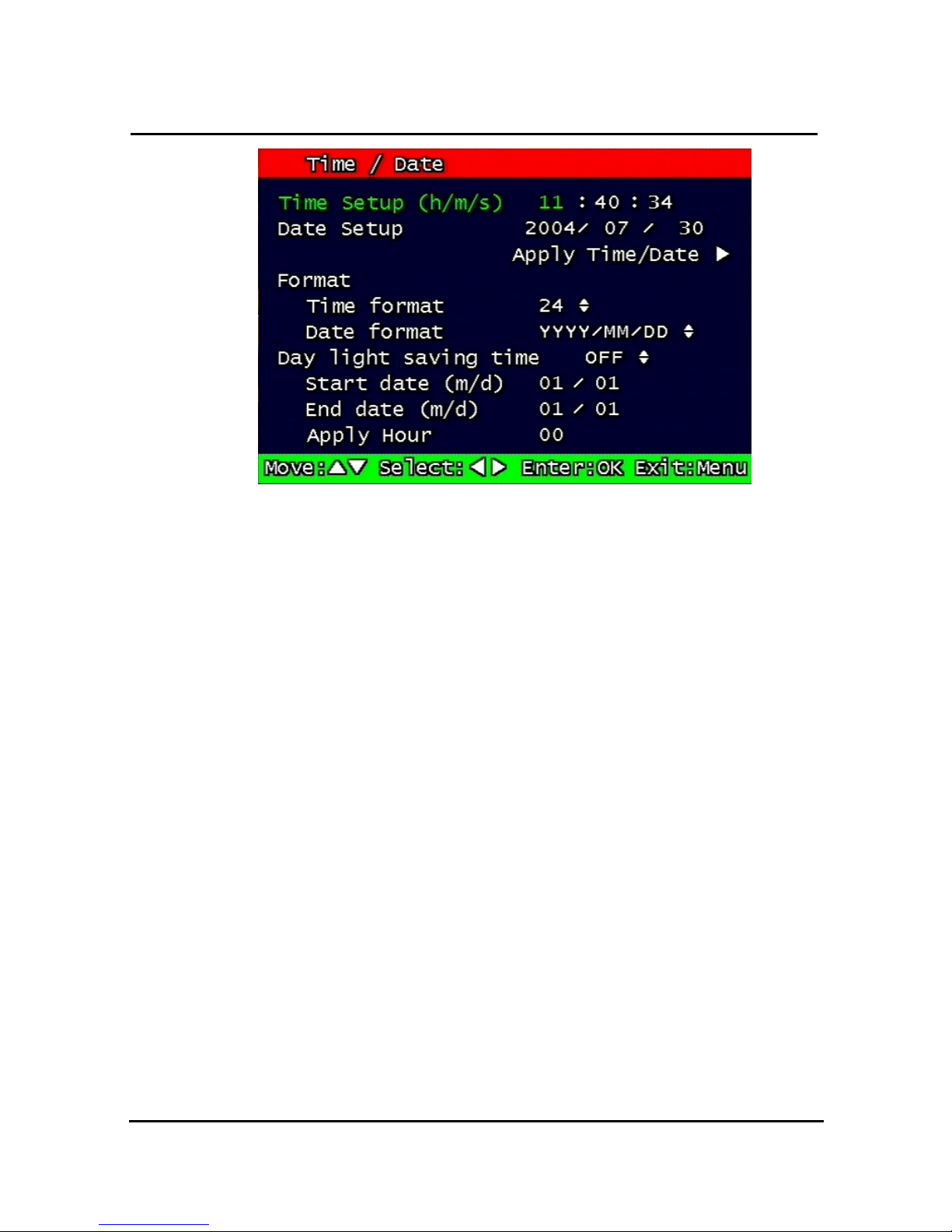
59
Figure. 0-31 Set up Time/Date
3.7.4.1 Set up Time / Date
Set up date and time on the system
3.7.4.2 Time / Date Format
Set up format for date and time. There are two types of time: 24hr circle/ 12hr circle. Date
format can be set up as the following: YYYY/MM/DD, MM/DD/YYYY, DD/MM/YYYY.
3.7.4.3 Day Light Saving Time
Set up Start Day and End Day in Day Light Saving Time mode
For example, if users adopt day light saving time from May 01 to Oct.31, input the dates
accordingly.
1. Start date (m/d)
Set up start day in Day Light Saving Time mode.
2. End date (m/d)
Set up end date in Day Light Saving Time mode.
3. Apply Hour
Configure Day Light Saving Time.
Page 63
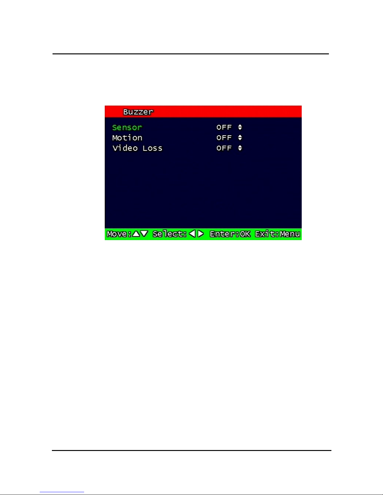
60
3.7.5 Buzzer
Users can turn the buzzer On/Off depending on the situations. Usable situation is Sensor,
Motion, & Video Loss. When users activate the buzzer, buzzer will make a sound when there
any event occurs. There would be no sound if the buzzer is turned Off.
Figure. 0-32
Set up buzzer
3.7.6 Language
English, Korean, Japanese and Spanish, French, german are available.
3.7.7 HDD Setup
Set up for Internal HDD and Removable HDD, See the information.
Page 64
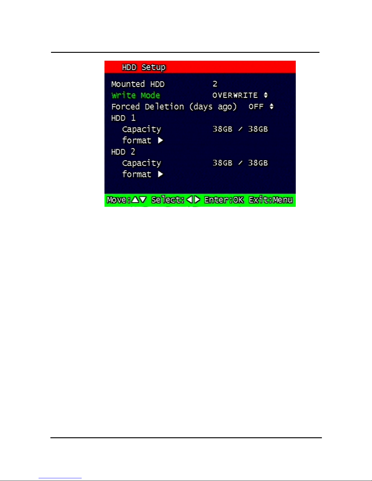
61
Figure. 0-33 HDD Setup image
3.7.7.1 The number of HDD
Show the HDD quantity that is built –in.
3.7.7.2 Write Mode
Set up writing type in recording.
Types are ‘Once’ and ’Overwrite’. If set up by ‘Once’, HDD can record until the Full state. If
set by ‘Overwrite’, HDD will record continuously by start overwrite oldest data.
3.7.7.3 Forced Deletion
The images recorded earlier than specific date can be erased by force.
The number of dates for erasure can be selected from 1 ~ 100.
In case that “off” is setup, the recorded images shall not be erased,.
In case that “30” is setup, the images recorded 30 days earlier than today shall be erased.
Page 65
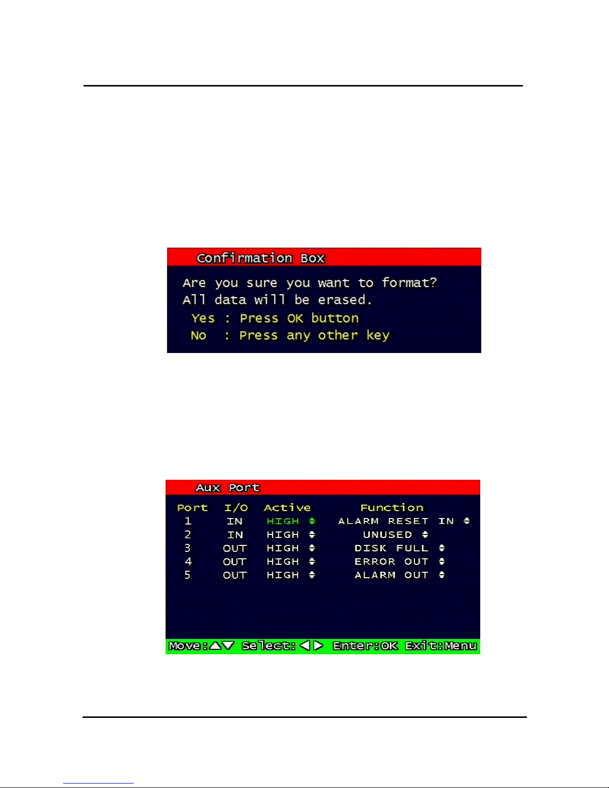
62
3.7.7.4 Hard Disk
1. Capacity
Indicate the used part and total capacity of Internal HDD.
Used part of HDD (GB) / Full capacity of HDD (GB)
2. Format
This is function for internal HDD formatting and you must reboot the system after this
instruction. Confirmation box on format will appear after entering format key. User can format
and erase all information of HDD, after entering ‘yes’ key button.
Figure. 0-34 Confirmation box for HDD format
Max 2 HDD can be installed. The added HDD works as a HDD, together with first HDD
3.7.8 Aux Port
Set up for Aux Port
Figure. 0-35
Set up AUX port screen
Page 66
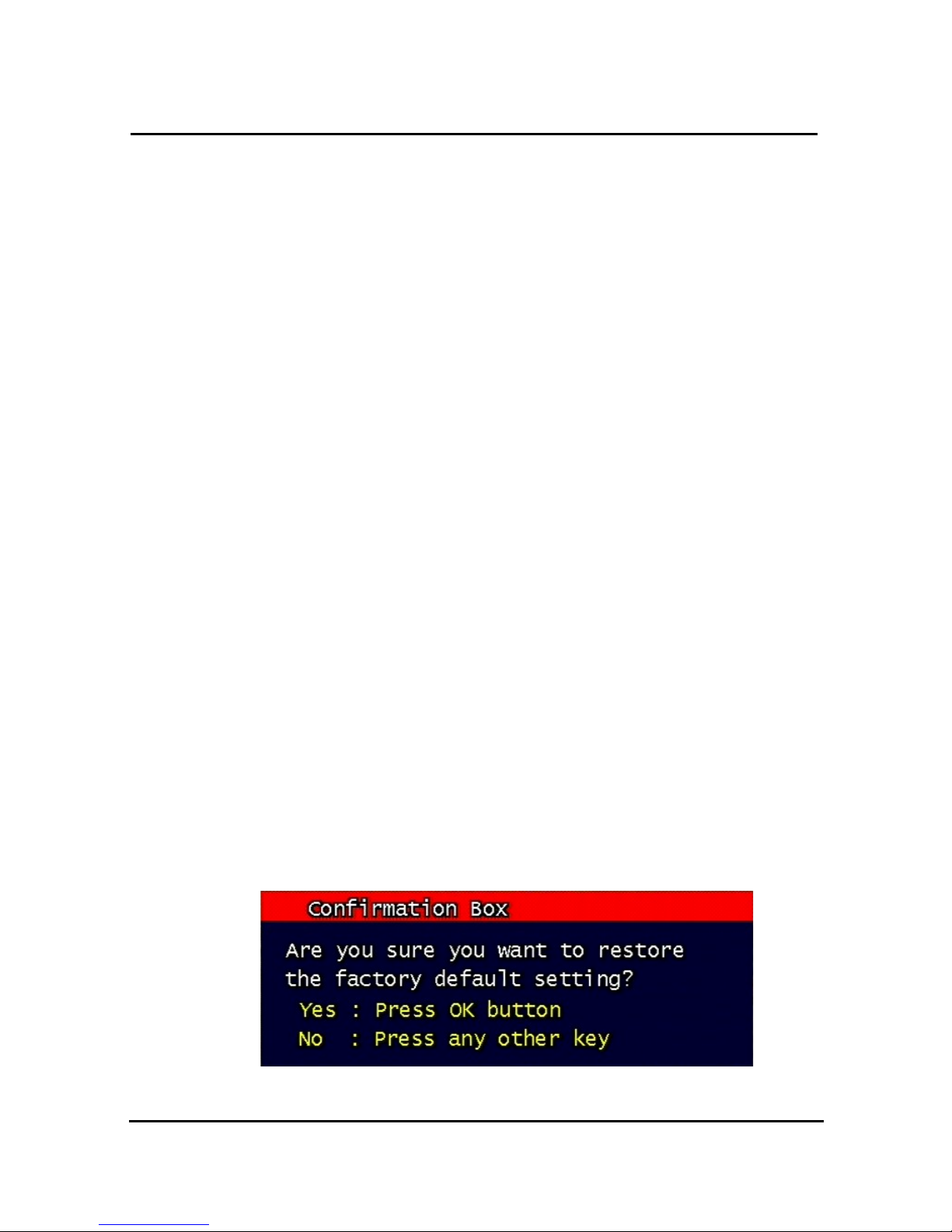
63
3.7.8.1 Active
Set up Active state. Low/High will be different depend on machine..
3.7.8.2 Function
The following list contains a brief description of each function.
1. Direction : IN
• UNUSED: Do not use the AUX port.
• ALARM RESET IN: Pause alarm or buzzer when event occurred
• RECORD START IN: Record image during user push the button
• RECORD ON/OFF: Recording start/stop during user push the button & same as
• pushing remote controller or DVR machine
2. Direction : OUT
• ALRAM OUT: Notice the assigned port when event occurred
• ERROR OUT: Notice the assigned port when system error occurred
• (Mark system error)
• RECORD START OUT: HDD of DVR is full, send signal to DVR which is connect with
AUX port. During receiving recording signal through AUX port,
it can record it and the mode of DVR AUX in port is RECORD
START IN.
• DISK FULL: If HDD is full, send signal to the AUX port.
• RECORD STATUS: Indicate whether it is recording or not
3.7.9 Factory Default
All of set-up date of system comes back to Factory default.
Confirmation box on picture setting default will appear after entering default. User can
restore the factory default setting after entering ‘yes’ key button.
Please refer to paragraph 5.3 for factory default.
Figure. 0-36 Confirmation box for Factory Default
Page 67
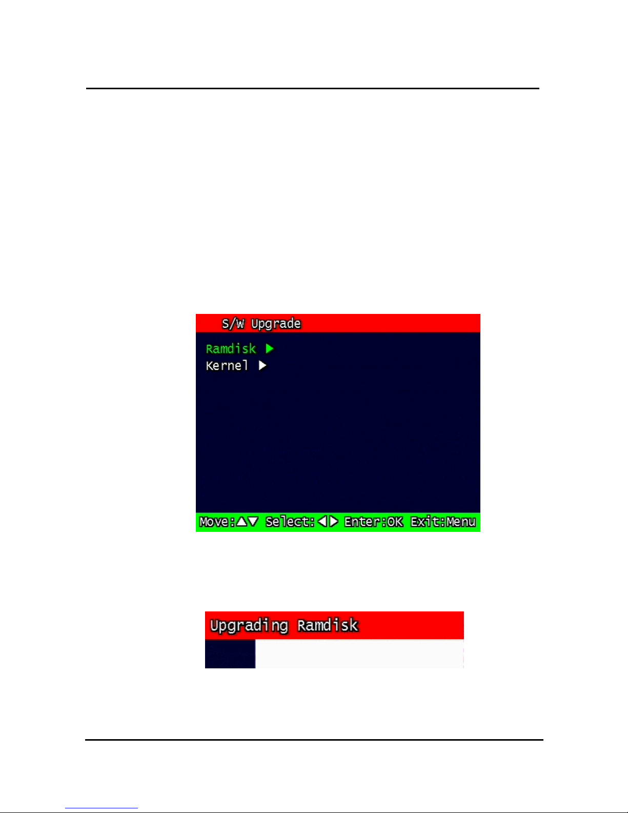
64
3.7.10 Software Upgrade
Users can upgrade the software of Ramdisk and Kernel using the USB flash drive
(thumb drive) by the following steps.
- Get the latest version of software (Ramdisk/Kernel) from distributor
- Copy the downloaded files from the PC to the USB memory.
- Connect the USB memory to the USB port.
- Go to 'System Setup' then 'S/W Upgrade' then select Ramdisk or Kernel to upgrade.
Figure. 0-37 Software Upgrade
- After the unit recognizes the USB flash drive and upgrading end, the unit will reboot.
Figure. 0-38 Ramdisk Upgrade
Page 68
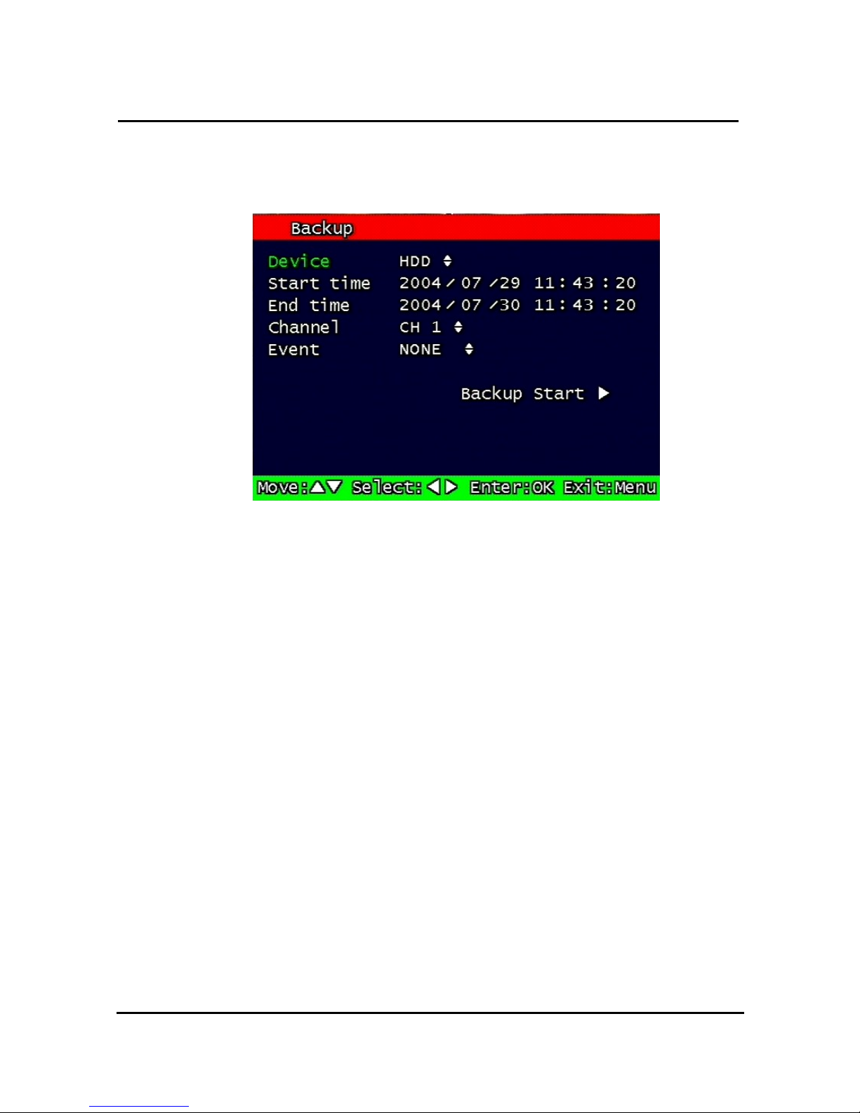
65
3.8 Backup
Backup recording data to HDD or USB Flash Drives
Figure. 0-39 Backup screen
3.8.1 Backup Device
Set up the device for backup. USB/ CD-RW are available
3.8.2 Start Time
Input the start of backup date and time.
3.8.3 End Time
Input the end of backup date and time.
3.8.4 Channel
Choose the channel to backup.
3.8.5 Event
Choose the event to backup. In case of none mode, selected files according to time will be
backed-up.
3.8.6 Backup Start
Based on the input date, time, channel and event & other condition search the images will be
backed-up to the chosen device. Back up progress rate is marked on the bottom right side of
the screen.
Page 69
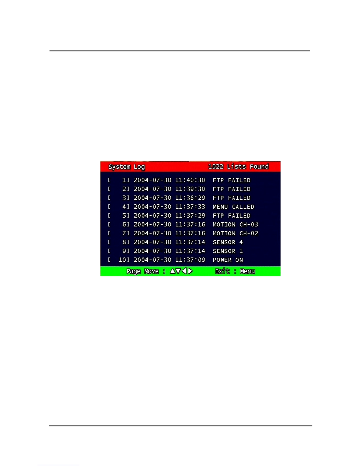
66
3.8.7 Format
This menu is used only when backup device is CD-RW. In case that backup device is CD-
RW, format command has to be done by this menu, before starting backup.
However, with CD-R media, backup can be started without format.
3.9 System Log
It is for displaying major system events.
The items that manage by Log are Video Loss, Power On, Power Off, Menu entry, HDD Full,
failure of FTP transmission, failure of E-mail transmission, failure of HDD
Figure. 0-40 System Log
Page 70
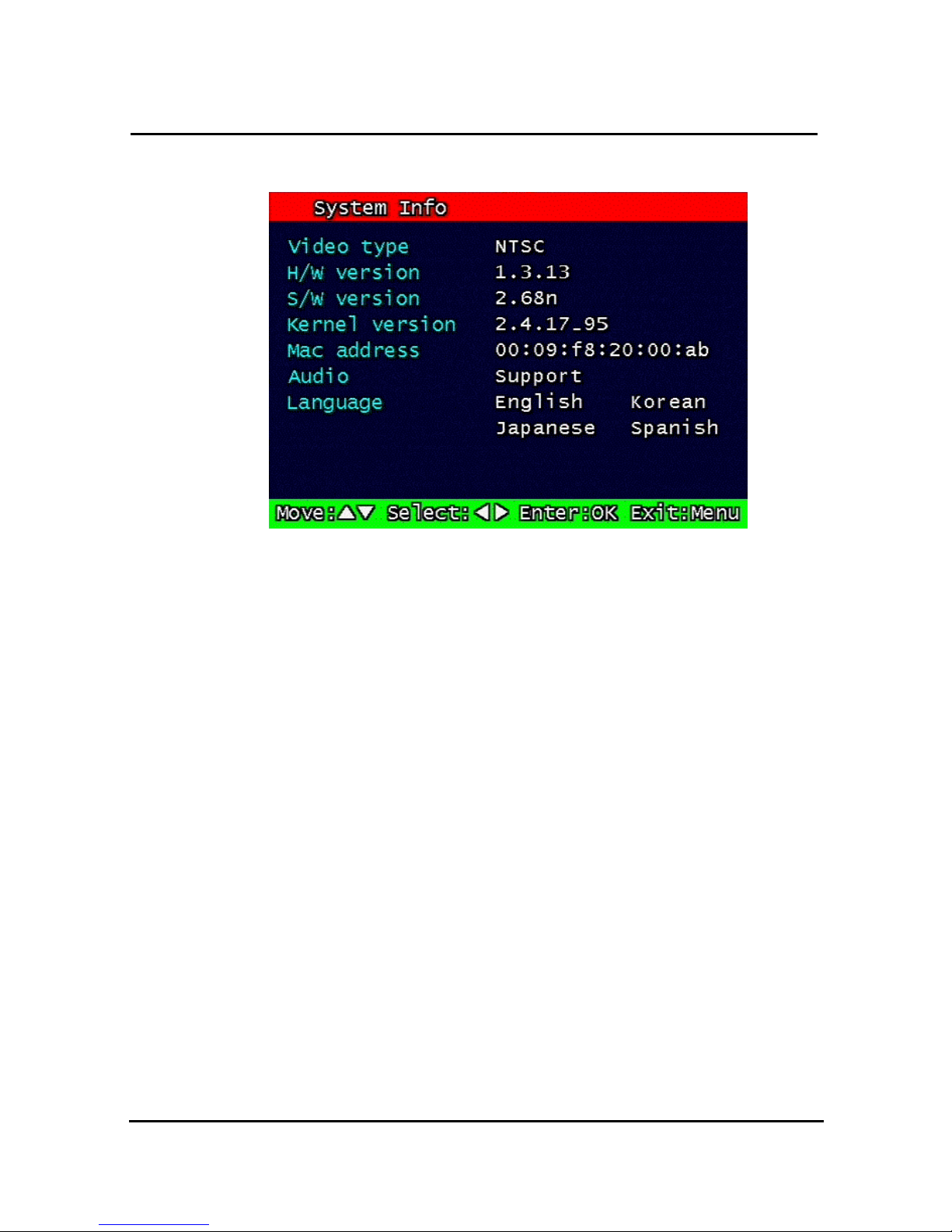
67
3.10 System Information
Figure. 0-41
System Information
3.10.1 Video type
It shows that present Video type of System is NTSC or PAL.
3.10.2 H/W version
It shows the H/W Version of system.
3.10.3 S/W version
It shows the S/W Version of system
3.10.4 KERNEL version
It shows the S/W Version of KERNEL.
3.10.5 Mac Address
It shows Mac Address of system
Page 71
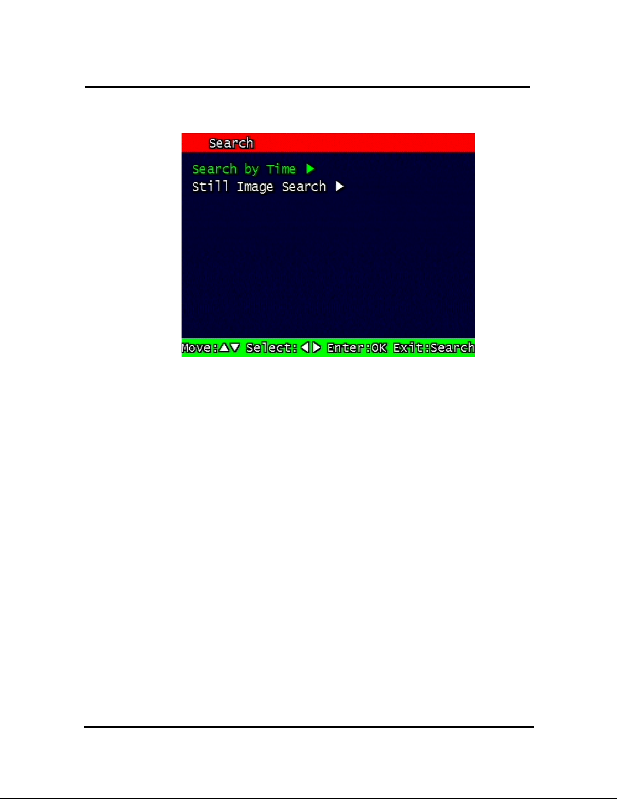
68
3.11 Search Menu
Figure. 0-42
Main Screen of Search
3.11.1 Search by Time
The recorded images are searched by Time, Channel, Event. DVR saves lat searching
condition so it automatically displayed last search condition under search mode.
** Screen where the condition of search will be input.
Page 72
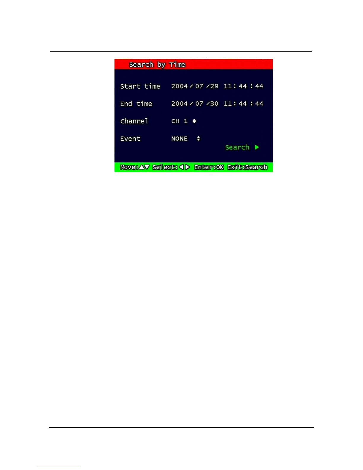
69
Figure. 0-43 Search by time
3.11.1.1 Starting Time
Starting Time and date for Search is input.
The starting year range is from 1970 to 2037, and it is not possible to input any year
after 2037.
3.11.1.2 Ending Time
Ending Time and date for Search is input.
The ending year range is from 1970 to 2037, and it is not possible to input any year
after 2037.
3.11.1.3 Channel
Select the channel for Search from Channel 1 ~ Channel 8.
3.11.1.4 Event
Select the Event as follows.
• NONE : All of files are searched regardless of Event.
• MOTION : The file recorded by MOTION is searched.
• SENSOR : The file recorded by SENSOR is searched.
Page 73
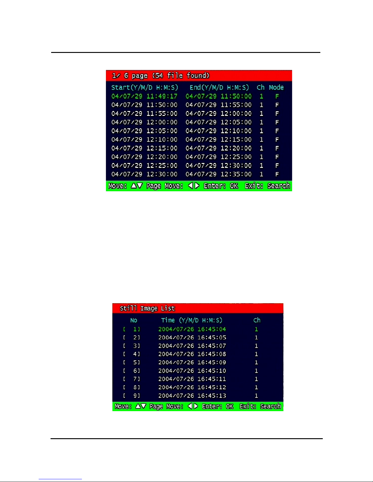
70
3.11.1.5 Example of Search Result
Figure. 0-44 Screen of result of search by time
3.11.2 Search of still image
Still image is not searched by Time and Channel.
If users press “search” Button, the still images recorded in the system appear from the oldest
one to latest one, and Maximum 99 still images can be stored and searched
3.11.2.1 Screen of search
Figure. 0-45
Search Screen of Still Image
Page 74
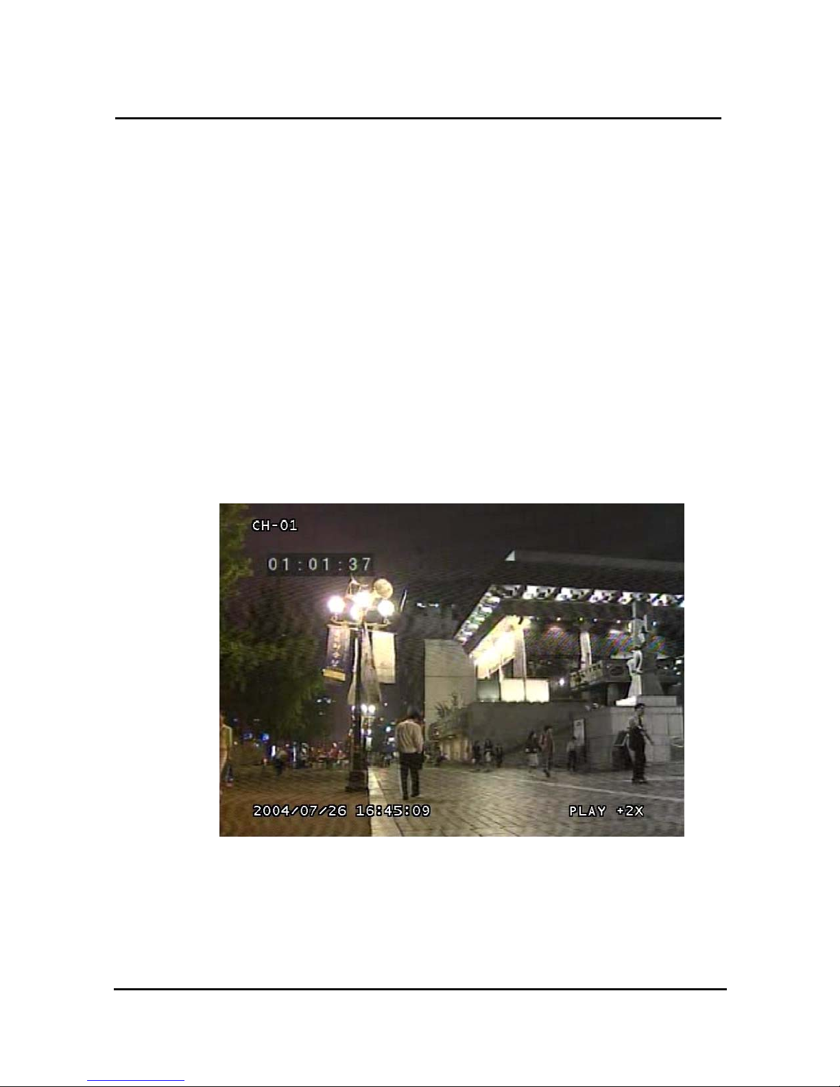
71
3.12 PLAYBACK
3.12.1 PLAYBACK of recorded Images
This function means that the images recorded in the system are searched by Time or Played
back directly.
3.12.2 Method of playback
In order to play back the recorded images, put the Curser to the selected content in the
Menu of Search, and press Button “ OK”.
The screen of Search results disappears and the selected images are played back.
The recorded files with Audio are played back with Audio.
3.12.3 Screen of played back.
Figure. 0-46
Screen of playback
Page 75

72
3.12.4 Control during play back
1.
Stop of Play back
If user needs to stop play back, user should press button “ STOP”
in the remote controller of in the system, and play back stops and live screen is coming back.
2.
Temporary Stop during Playback
In order to stop temporarily playback, press button “ PAUSE”.
If users press the button “PAUSE” again, play back continues.
3.
Speed level of Play back
There is 7 Speed levels for playback (Normal, Fast mode) in the forward and backward
direction as well.
There is 2 speed levels for slow playback mode in the forward and backward.
If user needs faster speed of playback, users press button “RIGHT” and speed is controlled.
If user needs slower speed of playback, users press button “LEFT” and speed is controlled.
4.
Change of Direction of Playback
There’s forward and Backward directions.
In order to change direction from Forward to Backward, user press the button
“ REVERSE PLAY” and backward playback starts with normal speed. On the
contrary, to change direction from Backward to Forward, user press the button
“PLAY” and Forward playback starts with normal speed.
5.
Select of channel of Playback
Select the channels by using button “ 1” ~ “8” and selected channels show the
image which recorded at simultaneous time. If there are recorded image, it will show
the image which close to recorded time at previous playback channel.
6.
Audio ON / OFF
In case of recorded image with Audio, user can on or off by using the button “ AUDIO MUTE”.
The Icon in the top of screen shows the status (On / Off) of AUDIO.
Page 76
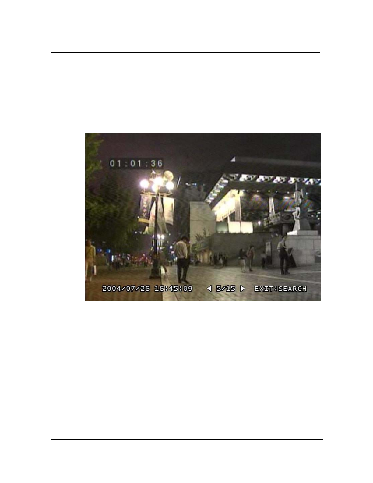
73
3.12.5 Playback of still image
3.12.5.1 Method of playback
As the paragraph 3.11.2, users put the curser to contents. In the searched still Image Lists,
and press Button “OK”.
The screen of search list disappears and still image is played back as the paragraph 3.11.2.
3.12.5.2 Screen of playing back
Figure. 0-47
Still Image of playing back
3.12.5.3 Control during Play back
1.
Stop of play back
To stop the playing back, User press button “STOP” or “ SEARCH”.
Playback stops and screen of search list appears.
2.
Next screen
Press Button “RIGHT” and next screen is played back.
Page 77

74
3.
Previous screen
Press Button “LEFT” and previous screen is played back.
3.12.6 Playback the backed up-image
This function means that the images in the backup HDD that were backed up manually or
automatically from the recorded images in the system are played back.
The functions for Playback of backed up images, screen during playback, control during
playback are same as those of Playback of Recorded images, as the paragraph 3.11.1
3.13 Miscellaneous Menu
Figure. 0-48 Miscellaneous Menu
This menu is to use the five functions that are placed only on the remote control but
on the keypad of the unit
3.13.1 NET
Displays the current network IP and the user connected to the network.
(it substitutes the NET button on the remote control).
Page 78
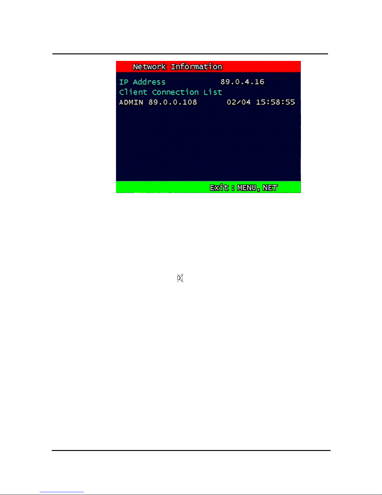
75
Figure. 0-49 Network Information
3.13.2 OSD
Turns on/off the OSD (On Screen Display). It substitutes the OSD button on the
remote control.
3.13.3 Audio Mute
Turns on/off the audio. It substitutes button on the remote control.
3.13.4 HDD
Displays the HDD information. It substitutes the HDD button on the remote control.
3.13.5 LOG
Display the System Log. It substitutes the LOG button on the remote control.
Page 79

76
4. DVR Client program
4.1 Overview of DVR
RAMS (Remote Access & Monitoring System) is used to remotely access, monitor, and
operate the DVR for real-time live viewing, playback, backup, on-the-fly recording, and control
over the LAN/WAN.
UniPlayer is a viewer with functions for recording, capturing, & backing up files.
Multiviewer is to monitor multiple DVR
QuickInstaller is a setup configuration template for quick & easy, multiple unit setup using RS-
232 or network. It can used to derive setting parameters of DVR system and to save setting
parameters to DVR system.
4.2 PC requirement (minimum)
Window 98
DirectX 8.0
Explorer 5.0
VGA Card for over 2 x AGP
Video card memory 64MB memory (the latest graphic cared driver)
Resolution 1024 x 768
4.3 Installation & execution of program
Please use DirectX 8.0 or newer.
- http://www.microsoft.com/windows/directx/default.aspx - English
- http://www.microsoft.com/korea/directx/default.aspx - Korean
To ensure optimal performance, install the latest graphics driver.
Install DVR by clicking on the Setup.exe file.
Rams.exe, Uniplayer.exe, and Multiviewer.exe, QuickInstaller.exe icons will be placed on the
desktop after a successful installation.
Page 80
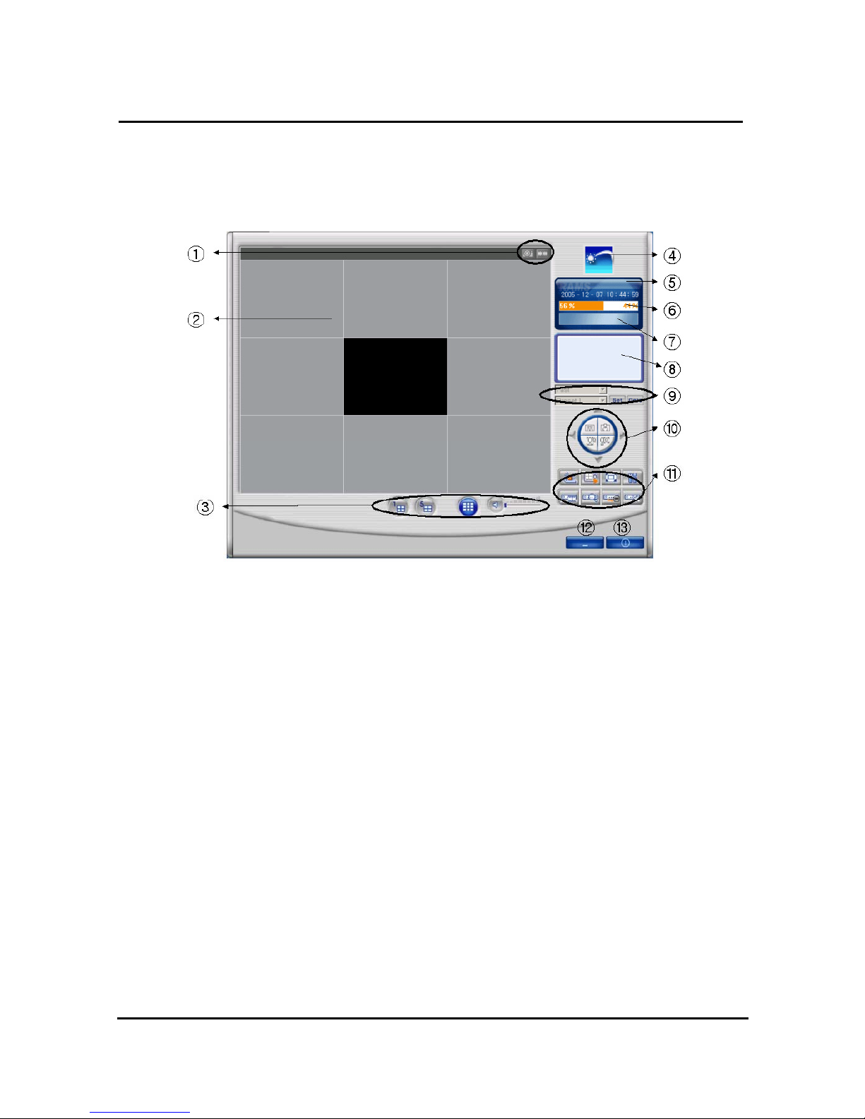
77
4.4 RAMS (Remote Access & Monitoring System)
4.4.1 Screen and button
① Screen capture button, Video record button
② Screen display
③ Channel display button, Sound control button
④ If logo is clicked, program version window appears.
⑤ Time indicator
⑥ PC HDD information indicator
⑦ Live or Playback mode indicator
⑧ Connected DVR information indicator
⑨ Preset
⑩ Pan/Tilt, Zoom/Focus button
⑪ DVR Connect button, UniPlayer link button, Full Screen button, Parameter setting button,
DVR recording button, DVR search & playback button, DVR retrieve & backup button,
DVR Setting button
⑫ Minimizing button
⑬ Close program
Page 81
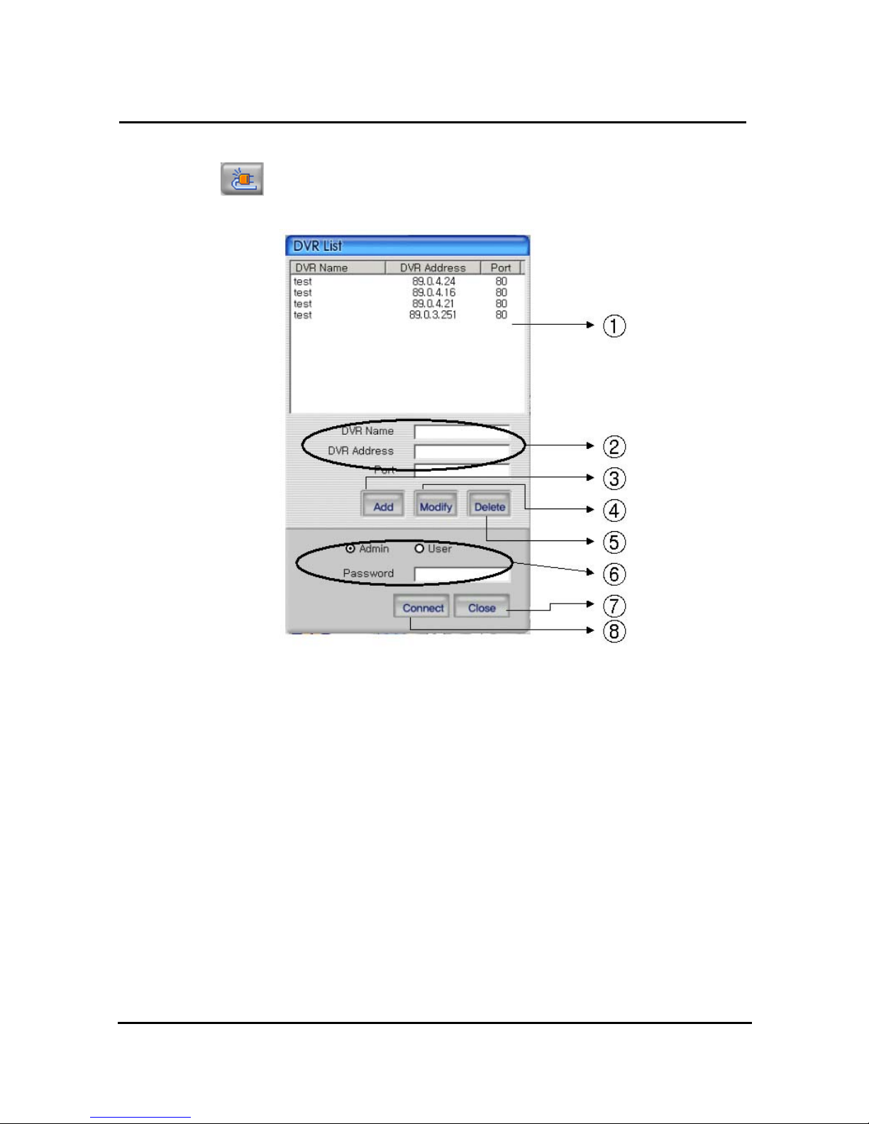
78
4.4.2 Connecting to DVR
Click icon to open the DVR list.
① This box allows the user to select the IP address assigned to the selected unit. This is
required for making a network connection.
② To create a new IP address & DVR selection, enter the DVR name, DVR address, and
port number.
③ To Click to add the newly entered DVR information into the DVR list
④ After selecting a DVR Name from the list and making changes, click Modify to update the
changes made to the item.
⑤ To remove an IP address/DVR Name , click and highlight the desired name, then press
the Delete button to remove.
⑥ Enter the correct password for either Admin or User for the target DVR.
⑦ Click Close to exit the DVR List
⑧ Click Connect after correct password has been entered to connect to the desired DVR.
Page 82
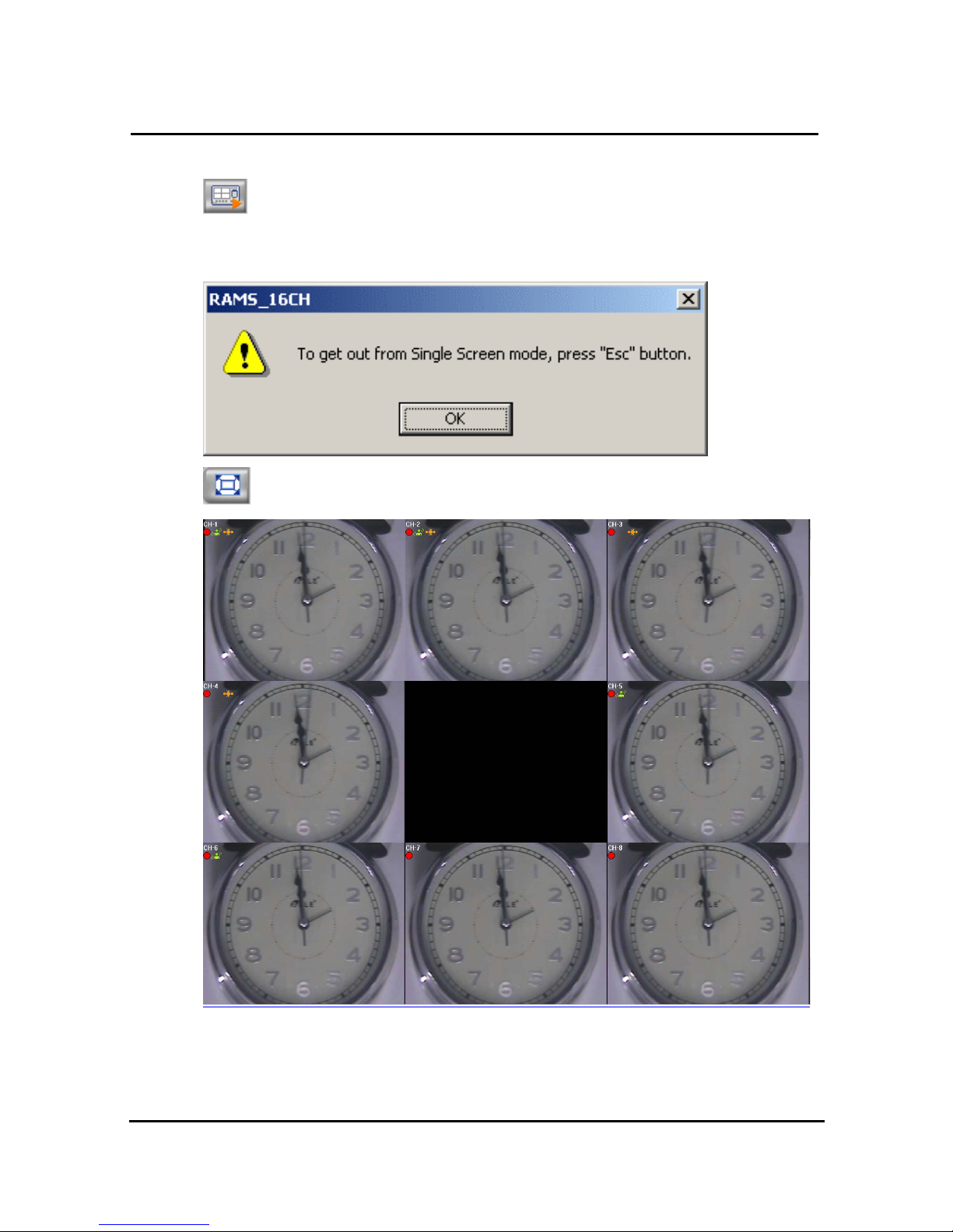
79
4.4.3 UniPlayer link
If you click this button on main menu, UniPlayer program will be executed.
Regarding the UniPlayer program, please refer to the article 4.4
4.4.4 Full-screen display
If you push this icon in the main menu, full screen form appears.
If users press the key of ESC, you will return to the selected screen.
OSD in the screen is same as that of DVR
Page 83
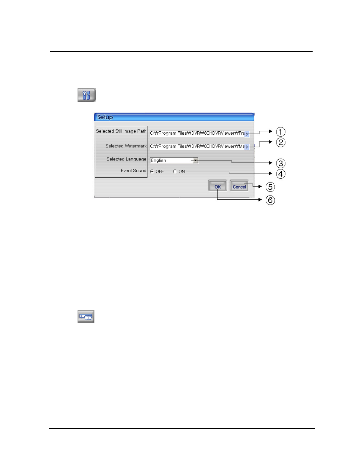
80
(Channel name, recording on/off, Motion icon, Sensor icon)
4.4.5 Program setup
If users click this button in the main window, window of program setup appears.
① Capture a still image and select a folder where the image is recorded
② Select the image of water mark to be input in the still image
③ Set up a program by user’s language
④ Set up whether alarm occurrence is on or off when motion detection or sensor icon
activated.
⑤ Close the window without saving the setup
⑥ Close the window after saving the setup
4.4.6 DVR recording
It works as recording button of DVR system. After logging in admin, button will be
activated. Under recording mode at DVR, red icon will be displayed at the top of right at the
window.
Page 84
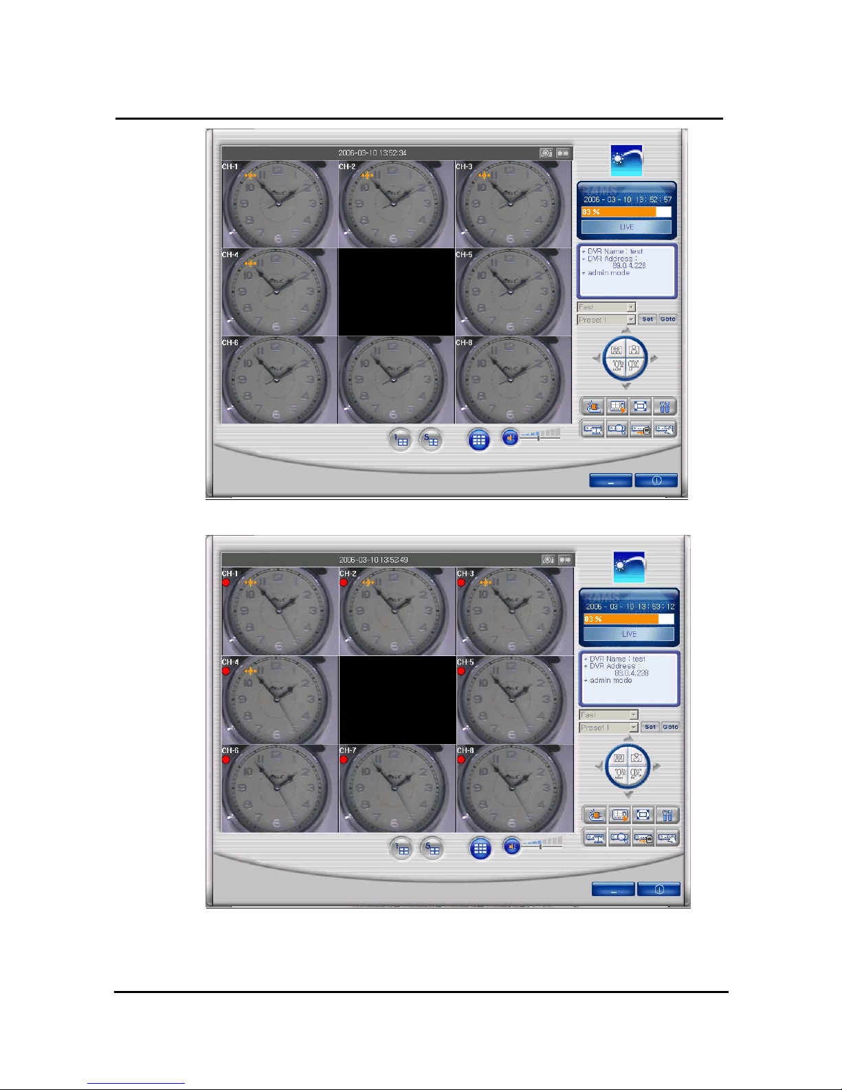
81
=> DVR (live viewing)
=> DVR (Recording mode)
Page 85
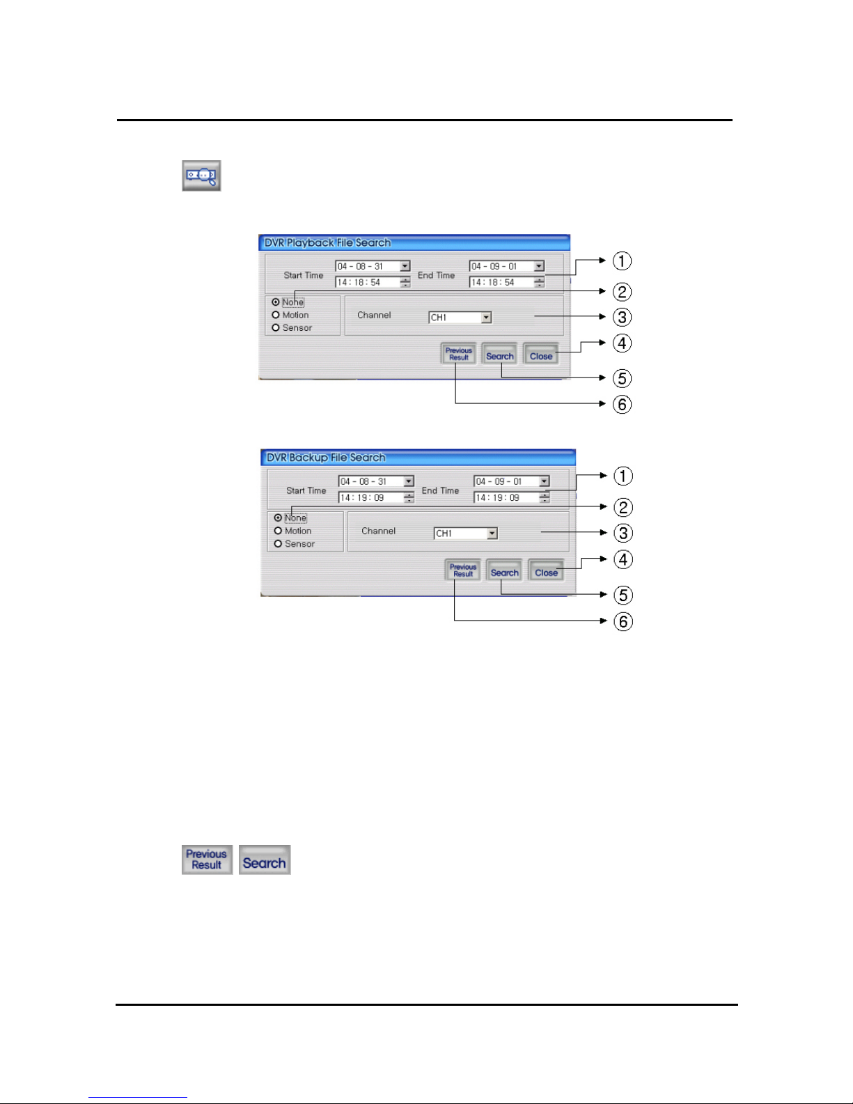
82
4.4.7 DVR playback search
This button is used for playback search, playback, and backup functions for DVR and
after logging in by admin.
① Enter search time from start time to end time
② Check if user want to search event condition
③ Select targeted channel for search
④ Close DVR playback search
⑤ Start to search by selected searching condition
⑥ Previous research result will appears
4.4.8 DVR playback search
Search data will appear list form if users push two buttons at DVR
playback screen.
Page 86
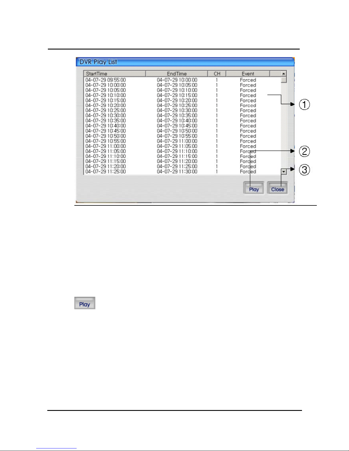
83
① DVR search files will appear recording start/end time, channel, and event information
included
② Button for staring of backup. With pushing selected channel, start to playback.
Start to playback after pushing selected channel,. If do double click selected files, it starts to
playback.
③ Close DVR backup window
After selecting a file at list, push play button or do double clicks in order to watch
playback pictures.
Page 87
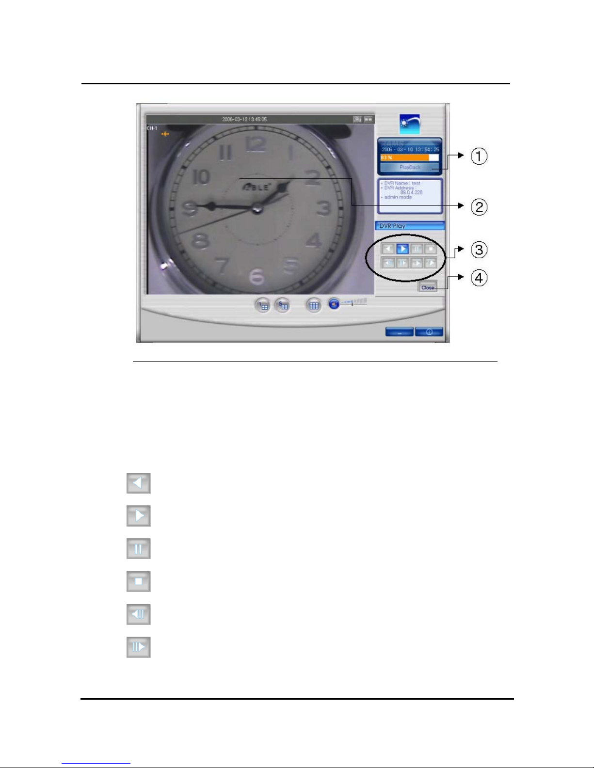
84
① Change present mode to playback mode
② Display playback picture derived from DVR system
③ Button for reverse playback, pause, still, reverse phase, forward phase, slow, fast, previous
search, next search
④ Comeback playback mode to Live viewing mode
Reverse playback button
Playback button
Temporarily pause button
Still image button
When user use temporarily pause image file move to backward
When user use temporarily pause image file move to forward
Page 88
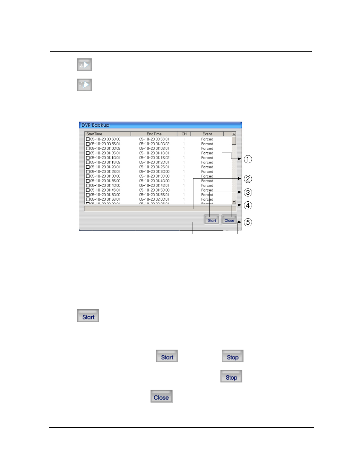
85
Play stored files slowly. User can control by clicking this button
Play stored files quickly. User can control by clicking this button
4.4.9 DVR backup
① DVR search files will appear recording start/end time, channel, and event information
included
② Indicator backup progress at backup
③ Button for staring of backup. With pushing selected channel, start to backup
④ Close DVR backup window
After selecting a file at DVR backup list, user can start to backup with pushing start
button
The destination of backup files is below of backup folder located in directory of program
installed. After starting backup,
button changes button, displays backup
progress rate. Even backup, users can stop it by pushing
button. Close DVR
backup window with pushing
button. (Even backup mode, it will be stopped &
closed.)
Page 89
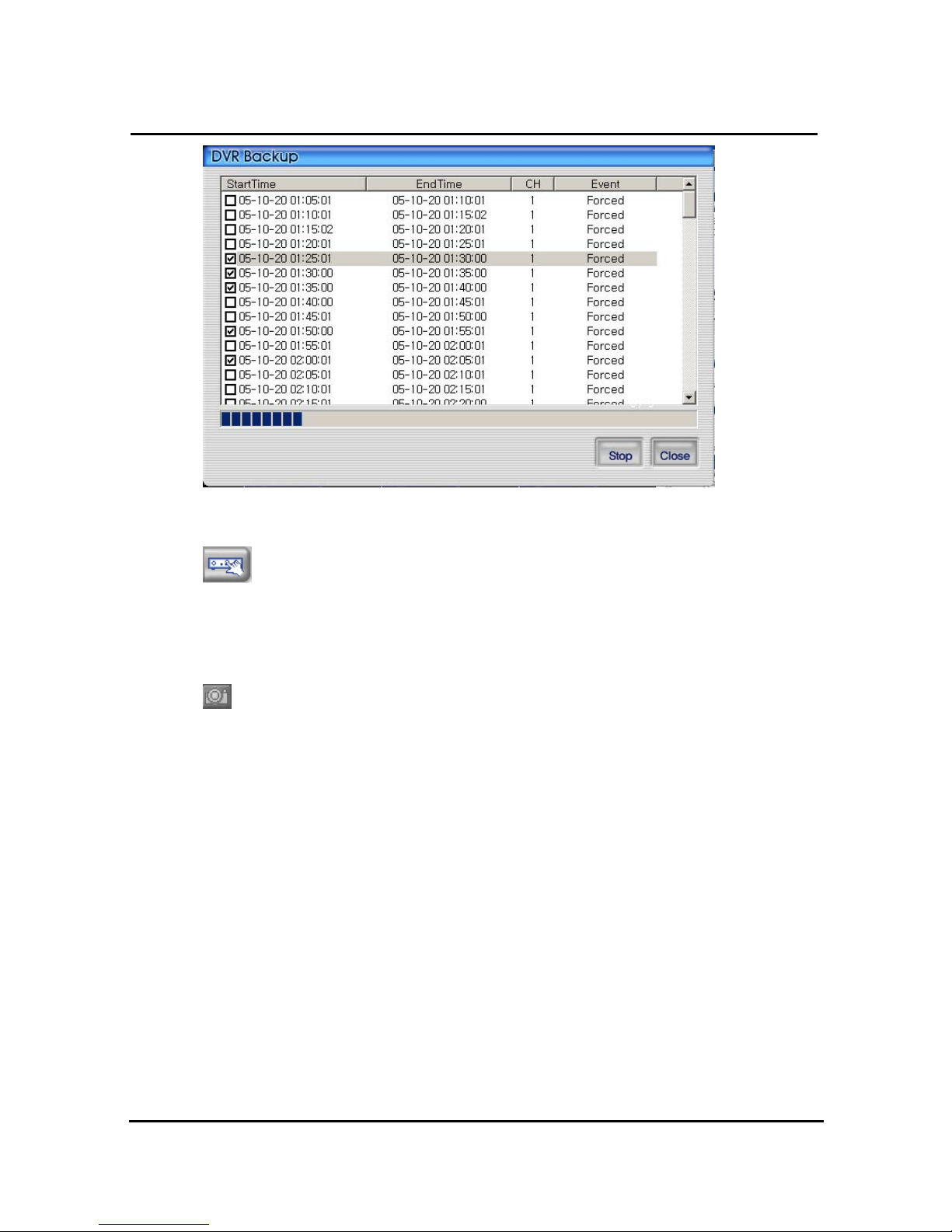
86
4.4.10 DVR Setting
This button is for linking into quick installation program, which is used to manage
setting parameter of DVR easily. It can be activated after logging in by admin.
The setting parameter of DVR are displayed.
4.4.11 Still image Capture
Yon can save playing image such as live viewing image, DVR playback image, into
still image by capture. Besides users can capture image by pushing capture button for each
channel or push capture button at the foot of a screen. Still image will be saved in a path
frame directory established in RAMS’s setup section screen. If user change storage path of
still image at setup window, still image will be recorded to destination in the future.
Page 90
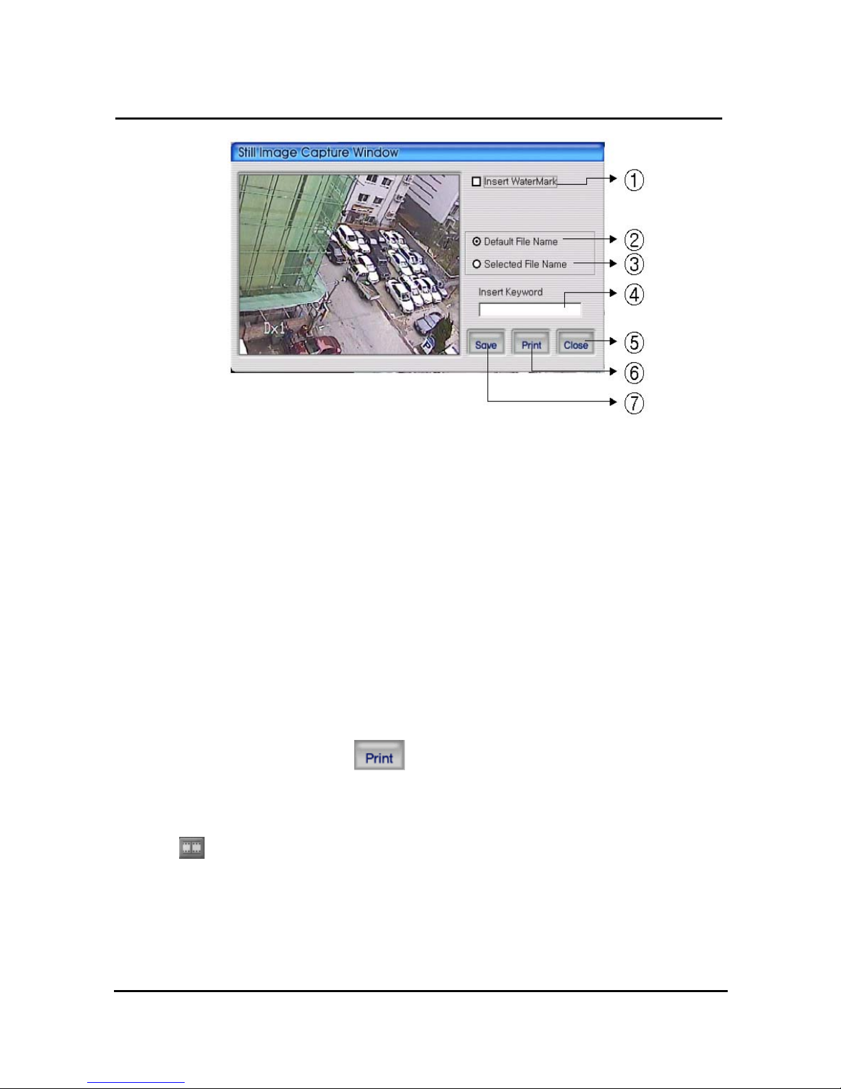
87
① Select check box in order to insert watermark into still image capture
② Save still image as user defined default file name if chosen
③ Save still image as user selected new file name if chosen
④ Insert keyword to user easy searching
⑤ Close still image capture window
⑥ Print still image capture file
⑦ Save still image. The destination of recording is assigned at still image recording, folder
through setup menu among RAMS program
4.4.12 Watermark insertion
Click the watermark checkbox then push the save button to save still image with watermark.
4.4.13 Printing still image
To print still image, please push icon in capture screen.
4.4.14 Motion picture recording
With live viewing picture, motion picture recording and saving at local PC
User can record each channel by pushing record button on top right side of channel or
pushing record button at below side of window. After pushing recording, record time setting
window will be popup. Users can change it or not.
Page 91
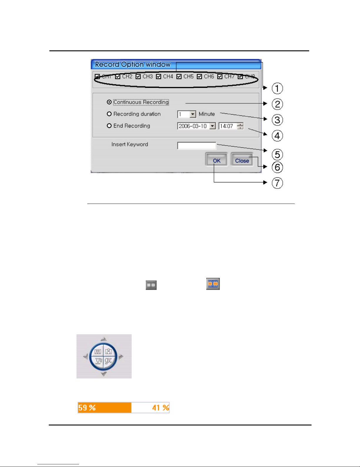
88
① Select the targeted channel changed recording time.
② Continuous recording until clients stop recording mode
③ Continuous recording until targeted minutes. Of course, it stopped manually by users
④ Continuous recording until targeted date & time. It stopped manually by users
⑤ For easy searching by keyword, client will insert keyword at search mode
⑥ Close record option window
⑦ After saving new selected recording option, automatically close it
With starting record, button
will be changed to button
In order to stop recording, users just push record button again & record. The recording
destination is record directory installed in Program.
4.4.15 PAN/TILT, ZOOM/FOCUS
These buttons are for PAN/TILT, ZOOM/FOCUS function of DVR
and after logging in by admin and/or one channel selected.
4.4.16 HDD Information
Page 92
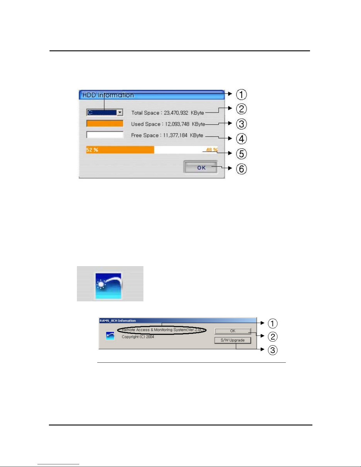
89
Orange: used parts of HDD,
White: remaining par of HDD. Detailed HDD information will be activated on pushing this
icon.
① Select hard disk
② It shows total capacity of HDD
③ It shows the used capacity of HDD used
④ It shows the capacity of HDD to be used
⑤ It shows the capacity of HDD used and to be used
⑥ Close the window
4.4.17 Check the program version
Click Logo to check program version or do S/W upgrade of DVR
system.
① Display the name & version of program
② Close the RAMS information window
③ Display S/W update window of DVR system
Page 93
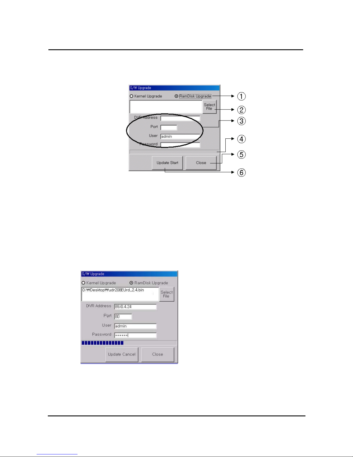
90
4.4.18 S/W upgrade of DVR
S/W upgrade window is activated on pushing S/W upgrade button in the program version
check screen
① : Select targeted files to upgrade
② : Select targeted files saved in local PC
③ : Enter targeted DVR information such as DVR address, Port, user, and password
(admin only)
④ : Indicator of targeted file’s transmission status
⑤ : Close upgrade window
⑥ : Transmit targeted files. After that, changed to upgraded cancel (cancel of upgrade
transmission)
=> Display status of SW Upgrade
4.4.19 Program minimizing
Rams program is minimized
Page 94
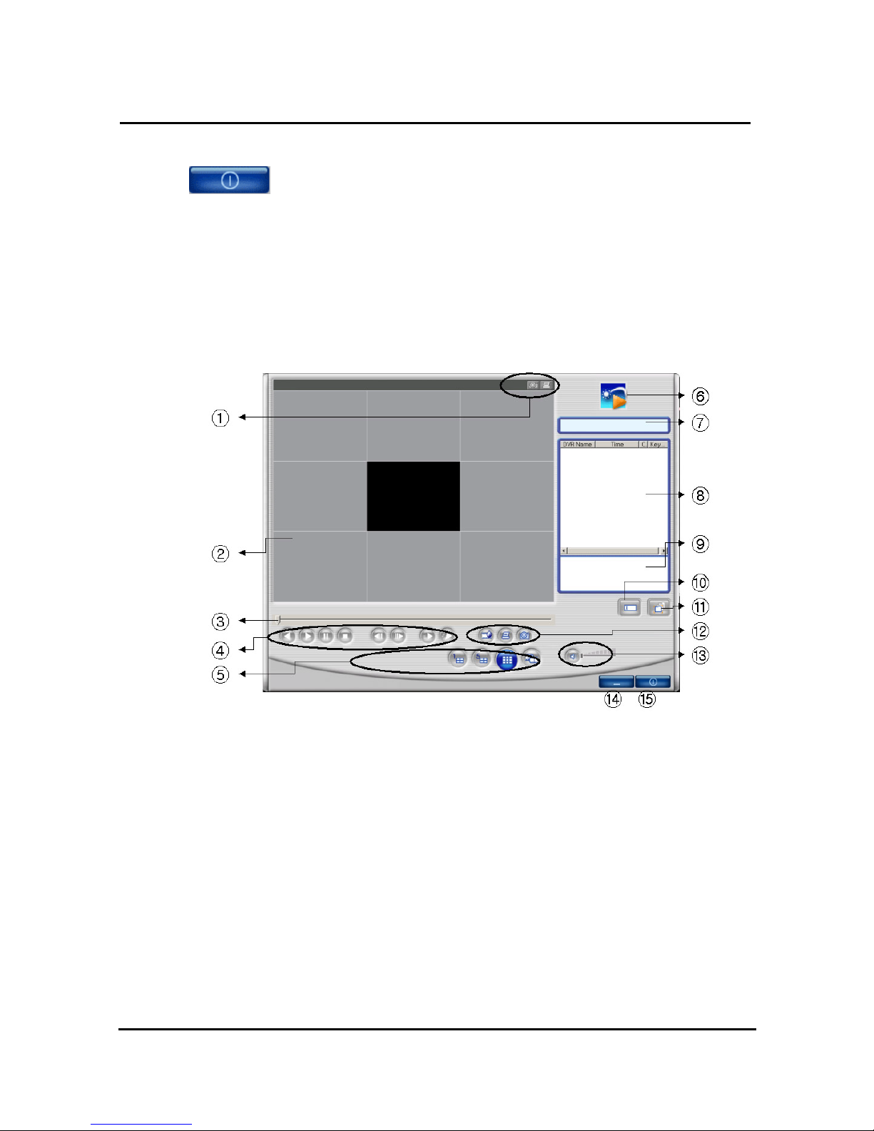
91
4.4.20 Close program
Closed Rams program
4.5 UniPlayer
4.5.1 Screen and button
① Button per channel (Capture, Print)
② Playback picture
③ Indicator for playback progress rate
④ Reverse playback, playback, still, pause, reverse phase, forward phase, slow, fast
⑤ Channel selection button, Panorama playback button
⑥ Click the logo to check program version
⑦ Uniplayer’s status
⑧ Search list
⑨ File path is displayed if selected at search list
⑩ Button for user searching
⑪ Button for directory based searching
Page 95
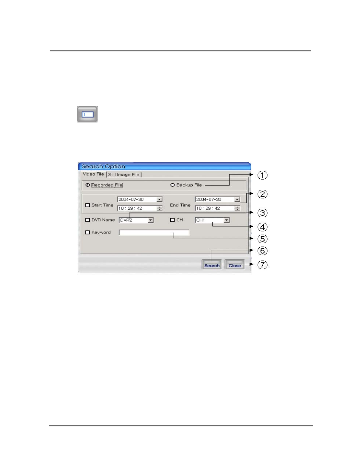
92
⑫ Retrieve button for watermark, printing, Capture
⑬ Button for sound On/Off, volume adjustment
⑭ Button for minimizing
⑮ Button for closing program
4.5.2 Search
Users access to search files after push this icon. As files are default mode, without
knowing of files, users can access it.
4.5.2.1 Search option from video image & backup file
① Select whether recording files at RAMS, Multiviewer or backup files
② Enter targeted recording date for search
③ Enter targeted DVR name for search
④ Enter targeted channel
⑤ Enter keyword to classification to list
⑥ Start to search accordingly
⑦ Close search option window
Page 96
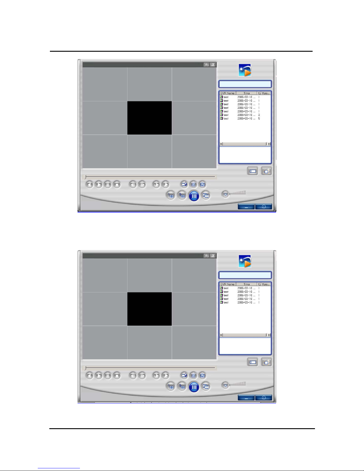
93
=> If there is nothing to special condition for searching, all files saved in recording folder will
be displayed on search window after searched.
=> Search window after selected channel number 1 as search option.
Page 97
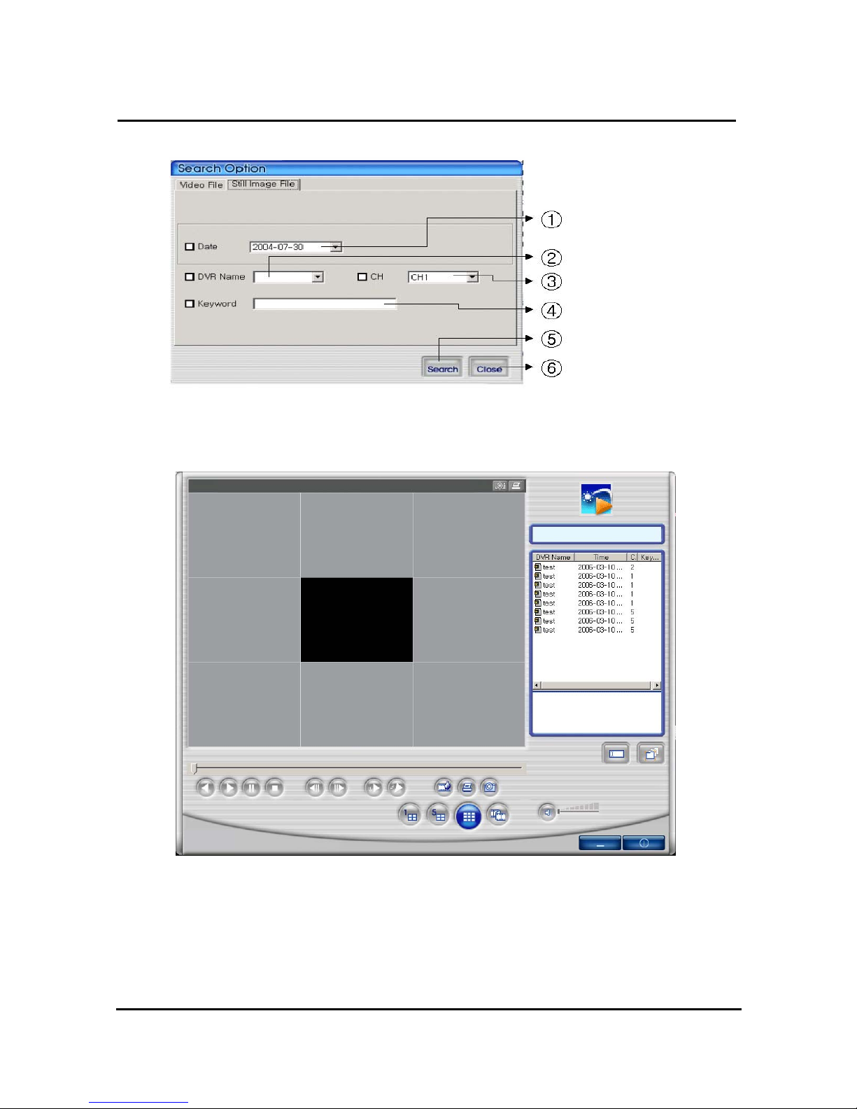
94
4.5.2.2 Search option for still image
① Enter targeted recording date for search ② Enter targeted DVR name for search
③ Enter targeted channel ④ Enter keyword to classification to list
⑤ Start to search accordingly ⑥ Close search option window
=> If there is nothing to special condition for searching, all still images saved in folder will be
displayed on search window after searched.
Page 98
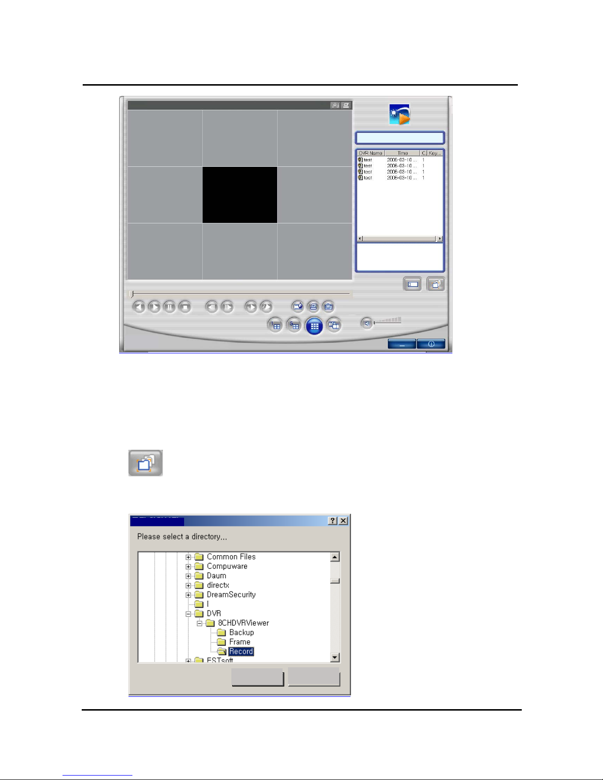
95
=> Search window after selected channel number 1 & selected date (Dec. 02, 2005) as
search option.
4.5.2.3 Searching by directory
You can use it when you know the directory has AVI file or still image file. It will be
set up default directory at first. After that users can choose their own directory than see all
folder user want to save will be on the list.
OK
CANCEL
Page 99
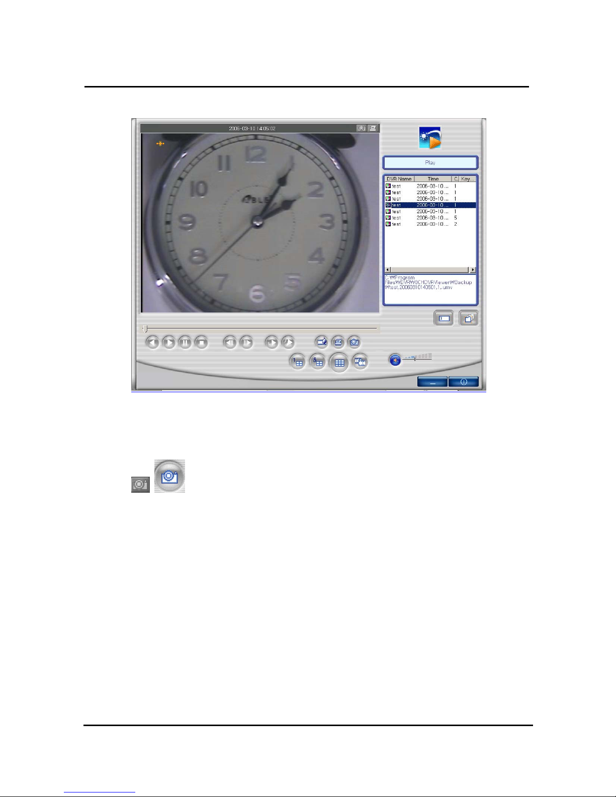
96
=> AVI file Playing screen by searching scene
4.5.2.4 Still Image Capture
Save replaying images into still image by capture. Besides users can capture
image by push capture button for each channel or push capture button at the foot of a screen.
Still image will be saved in a path of which is established in RAMS’s setup section screen
Page 100
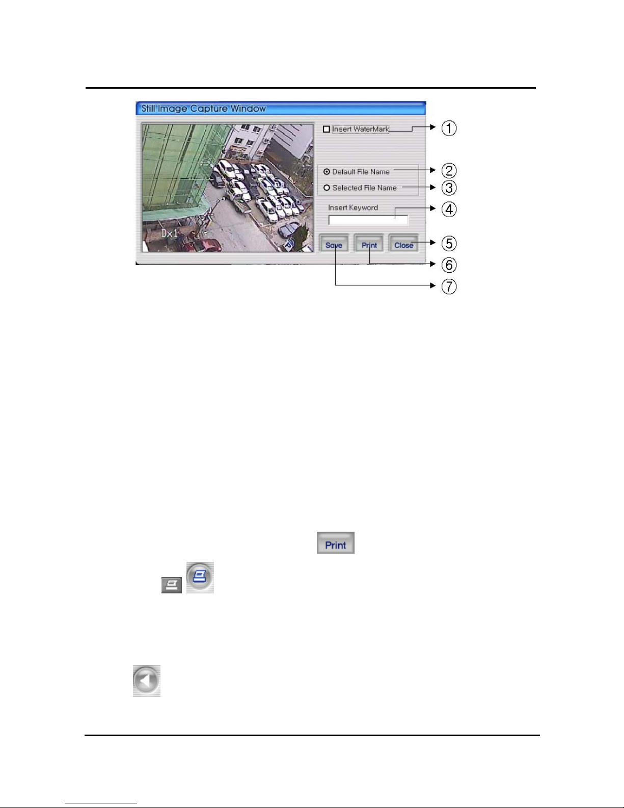
97
① Select check box in order to insert watermark into still image capture
② Save still image as user defined default file name if chosen
③ Save still image as user selected new file name if chosen
④ Insert keyword to user easy searching
⑤ Close still image capture window
⑥ Print still image capture file
⑦ Save still image. The destination of recording is assigned at still image recording folder
through setup menu among RAMS program
4.5.3 Input water mark
Click the Water Mark checkbox then push the save button to save still image with watermark.
4.5.4 Printing still image
To print still image, please push the button in capture screen. Then use this
button in main page. But In the motion picture state, this button only is
applicable to pause or temporarily pause mode.
4.5.5 Moving picture file playback, playing, pause, temporarily pause, move
by interval of frame, fast forward Playing
Playing-back image file
 Loading...