

Page 1
Vicon part number 8009-8170-01-02 Rev 709 Section 10
XX170-01-02
MODEL V-DA-8-16
16-CHANNEL VIDEO
DISTRIBUTION AMPLIFIER
Copyright © 2009 Vicon Industries Inc. All rights reserved.
Product specifications subject to change without notice
Vicon and its logo are registered trademarks of Vicon Industries Inc.
VICON INDUSTRIES INC., 89 ARKAY DRIVE, HAUPPAUGE, NEW YORK 11788
TEL:631-952-CCTV(2288) FAX:631-951-CCTV(2288) TOLL FREE:800-645-9116
24-Hour Technical Support:800-34-Vicon (800-348-4266)
UK:+44(0)1489-566300 WEB: www.vicon-cctv.com
Page 2

Vicon Part Number 8009-8170-01-02 Rev 709
1
Page 3

Vicon Part Number 8009-8170-01-02 Rev 709
2
Contents Page
Items delivered 3
General product information 3
Tips for mounting 3
System overview 4
Connecting and Operating 5
Internal adjustments 6
Troubleshooting 7
Maintenance and Care 7
Technical specifications 8
Technical Support 9
Your notes 10
Coaxial Cable Specifications 11
Vicon Standard Equipment Warranty 12
Page 4

Vicon Part Number 8009-8170-01-02 Rev 709
3
Items delivered
V-DA-8-16: Video distribution amplifier that can be rack mounted (1 RU) or set on a
desk. A separate power supply is provided with the unit.
Tips for mounting
- Install the video distribution amplifier indoors only.
- To avoid overheating:
- do not expose the unit to direct sunlight
- keep sufficient distance from direct heat sources
- leave enough space (at least 1 RU) in the rack between units for cooling
- Do not install the unit at damp, oily or dusty locations.
- Do not expose the unit to strong vibrations.
Page 5
Vicon Part Number 8009-8170-01-02 Rev 709
4
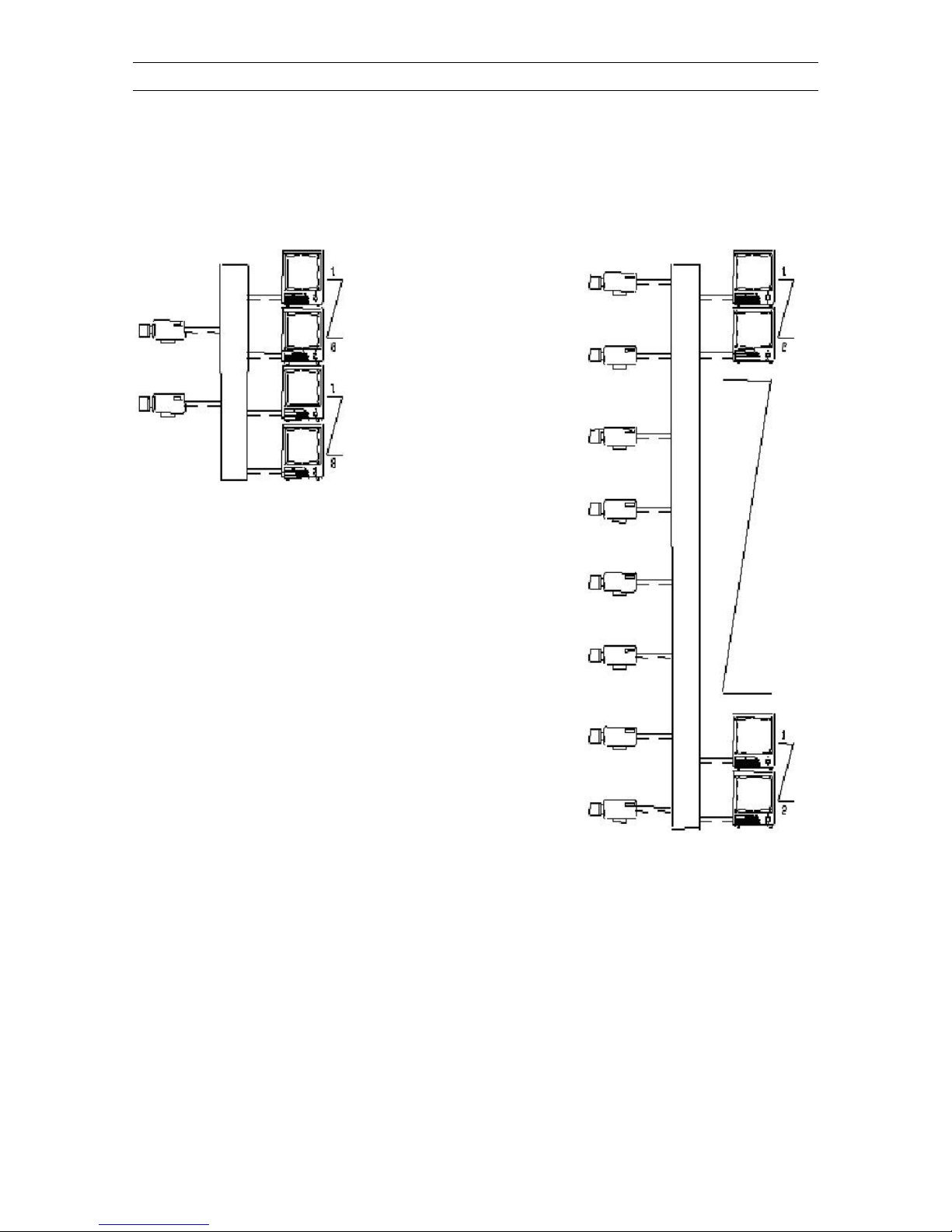
System overview
Configuration options:
Page 6
Vicon Part Number 8009-8170-01-02 Rev 709
5
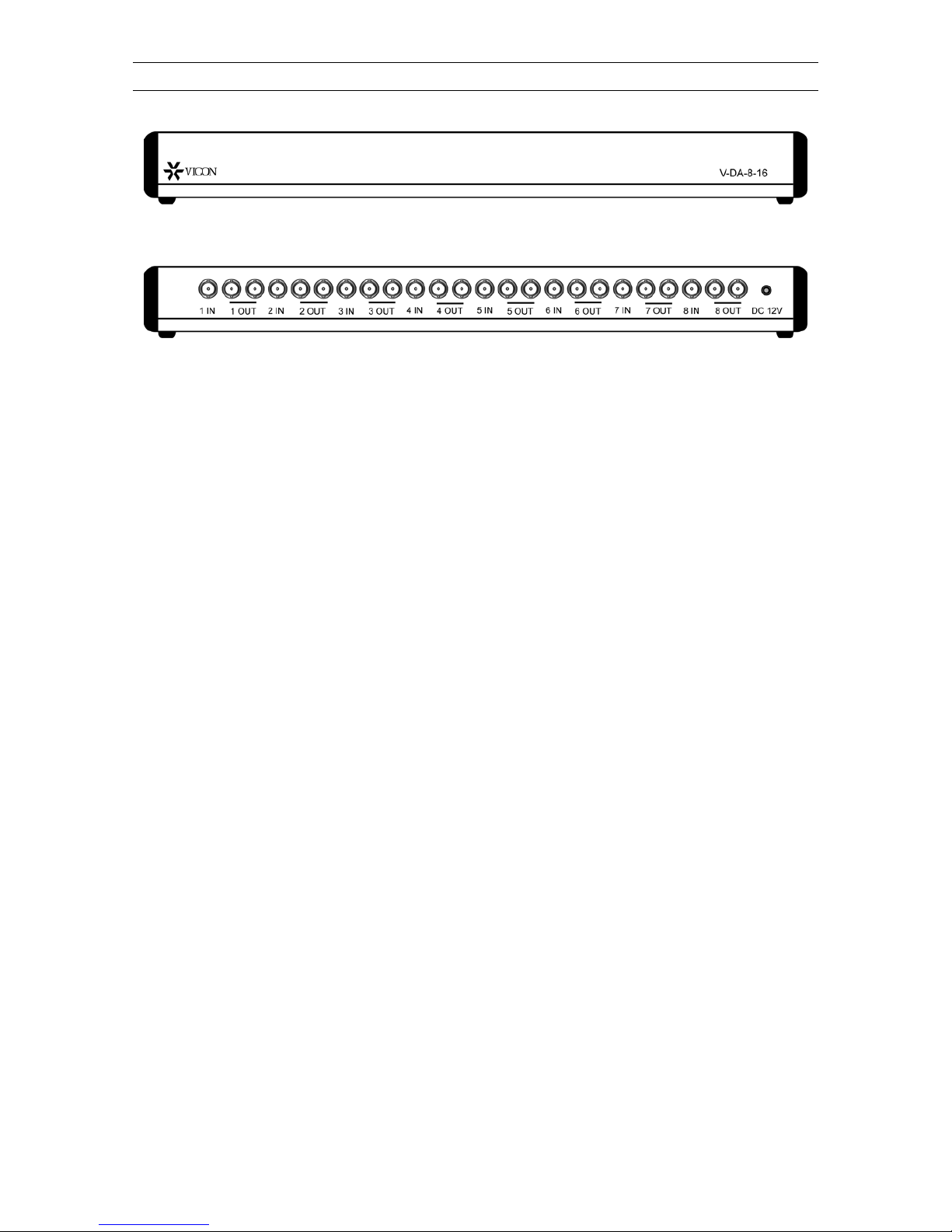
Connecting and Operating
The V-DA-8-16 can be configured as follows:
2 video inputs with 8 outputs each
4 video inputs with 4 outputs each
8 video inputs with 2 outputs each
1 video input with 16 outputs
Page 7
Internal Adjustments
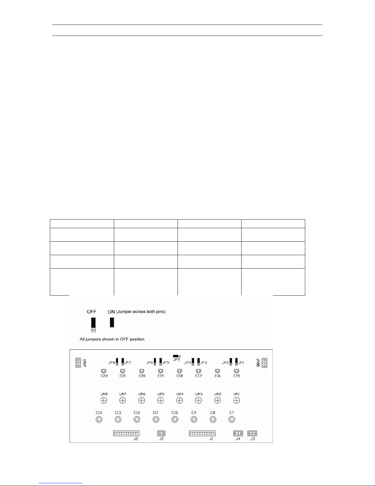
The V-DA-8-16 contains two identical circuit car d boards that can be configured to provide different combinations of video inputs and video outputs. This is accomplished by
setting jumpers on the boards, which are located inside the unit.
The factory setting is 4 video inputs and 4 video outputs.
To change the inputs and outputs, you must open t he unit and set the jumpers as fol-
lows:
1. Disconnect the unit from power supply.
2. Loosen and remove the allen screws from each end cap usin g th e su pplie d allen
wrench.
CAUTION: Use care when separating the top and bottom housings to ensure that no
internal wiring is disconnected or damaged.
3. Separate the top and bottom housings.
4. Set the jumpers on both boards as follows:
Note: The boards are connected by a jumper cab le to j ump er s J10 0 an d J10 1, which
combines the boards. Disconnecting the cable will create two separate amplifiers.
Configuration Jumpers On Jumpers Off Notes
8 video inputs with 2
outputs each
4 video inputs with 4
outputs each
2 video inputs with 8
outputs each
1 video input with 16
outputs
JP2, JP4, JP6, JP8 JP1, JP3, JP5, JP7,
JP9
JP1, JP2, JP3, JP5,
JP6, JP7
JP1, JP2, JP3, JP5,
JP7, JP9
JP1, JP2, JP3, JP5,
JP7, JP9
Note: One board must
have JP2 set to off.
JP4, JP8, JP9 J100 and J101 dis-
JP4, JP6, JP8 J100 and J101 dis-
JP4, JP6, JP8 J100 and J101 con-
J100 and J101 disconnected.
connected.
connected.
nected.
Vicon Part Number 8009-8170-01 -0 2 Rev 709
6
Page 8

Vicon Part Number 8009-8170-01-02 Rev 709
7
Troubleshooting
Error Cause
Video outputs are not all
available
(e.g. 1 video input
6 video outputs)
The jumper on the circuit board is set
to duplicated number of video inputs/outputs
One or several monitors
have stripes in the picture
These distortions are caused by hum
in the picture which is a result of
connecting several monitors to different potentials.
1. Connect all devices to the same
phase
2. Use galvanic transformers between monitor and mains phase
3. Use an additional optocoupler for
each transmission line
The monitors have no
picture
1. Video signal lines interrupted or
defective; check all coaxial cables and BNC plugs
2. Power supply to camera
interrupted; check operating
voltage at camera
3. The video distributor is off:
a. Check and/or replace
mains fuse
Should none of the above remedies be successful, please contact your authorized
dealer with a detailed failure description.
Maintenance and care
Before starting to clean the device, disconnect the unit from power supply. Never use
any water or fluid to clean the device for reasons of electronic safety. Never put the unit
under water. To clean use a soft dry cloth. Never open the unit to clean inside. This
may only be done by authorized personnel according to the local safety regulations. If
the device will be handed over to third parties, make sure to include these operating
instructions.
Page 9

Vicon Part Number 8009-8170-01-02 Rev 709
8
Technical specifications
Number of video inputs
and outputs
2 video inputs with 8 outputs each
4 video inputs with 4 outputs each
8 video inputs with 2 outputs each
1 video input with 16 outputs
Frequency
20 MHz / - 3 dB
Application
indoor
Scanning system
CCIR / PAL 625 lines, 50 Hz
EIA / NTSC 525 lines, 60 Hz
Signal-to-noise ratio
> 56 dB
Input signal
(F)BAS 1 Vpp / 75 Ω
Output signal
(F)BAS 1 Vpp / 75 Ω
Operating voltage
12 V DC
Consumption
2.4 W
Operating temperature
14° to 140° F (- 10° to + 60° C)
Air humidity
up to 90 %
IP rating / class
IP40/cl. III
MTBF
120.000 hours
EMI
acc. to EN 50081-1, EN 55011 class B
EMC
acc. to EN 50082-2,
EN 61000-4-2, -3,-4, -6, EN 50204
Safety
acc. to EN 60950, EN 60065
Housing finish
Aluminum
Housing colour
Aluminum
Weight
7 lb (3200 g)
Dimensions
(W x H x D)
17.3 in L x 1.85 in H x 5 in D
(440 x 47 x 128 mm)
19" (1 HU)
Connections
Video IN
Video OUT
Power
BNC-F
BNC-F
Low voltage socket
Accessories included
Operating manual, power supply
Page 10

Vicon Part Number 8009-8170-01-02 Rev 709
9
Technical Support
Should you have any problems during installation you can reach our Technical Hotline
at the following telephone number: 1-800-34-VICON (1-800-348-4266)
Page 11

Vicon Part Number 8009-8170-01-02 Rev 709
10
Your notes
Page 12
Vicon Part Number 8009-8170-01-02 Rev 709
11
Coaxial Cable Recommendations
Caution: Careful selection of proper cable is essential to obtain the best performance from this equipment. Vicon assumes no
responsibility for poor performance when cables other than those recommended, or equivalent, are installed. In all cases, coaxial
cable impedance should be 75 ohms.
Materials
Use only a pure copper center conductor. Do not use a copper-plated steel or aluminum center conductor, as they
will result in poor quality video. Solid-core bare copper conductor is the best type, where flexing and bending will be
minimal. If severe bending and flexing is required for installation, use a stranded center conductor. Never exceed the
manufacturers minimum bend radius specification. Use cellular (foam) polyethylene dielectric except where heavy
moisture exists. For moisture conditions, use solid polyethylene dielectric cable with a heavy exterior insulation. The
shield must be copper braid providing 95% or better coverage.
Cable Types
The cable types listed below are the most common 75-ohm types used. They vary in size (diameter), dielectric type
and net DC resistance. The larger cable results in a lower DC resistance and better video quality, with increased
difficulty in handling and installation. Let the required picture quality and cable distance provide a guide in choosing
the best cable type. For cables other than the approved Vicon types below, contact the manufacturers listed below.
Note that “BC” refers to bare copper and “TC” refers to tinned copper.
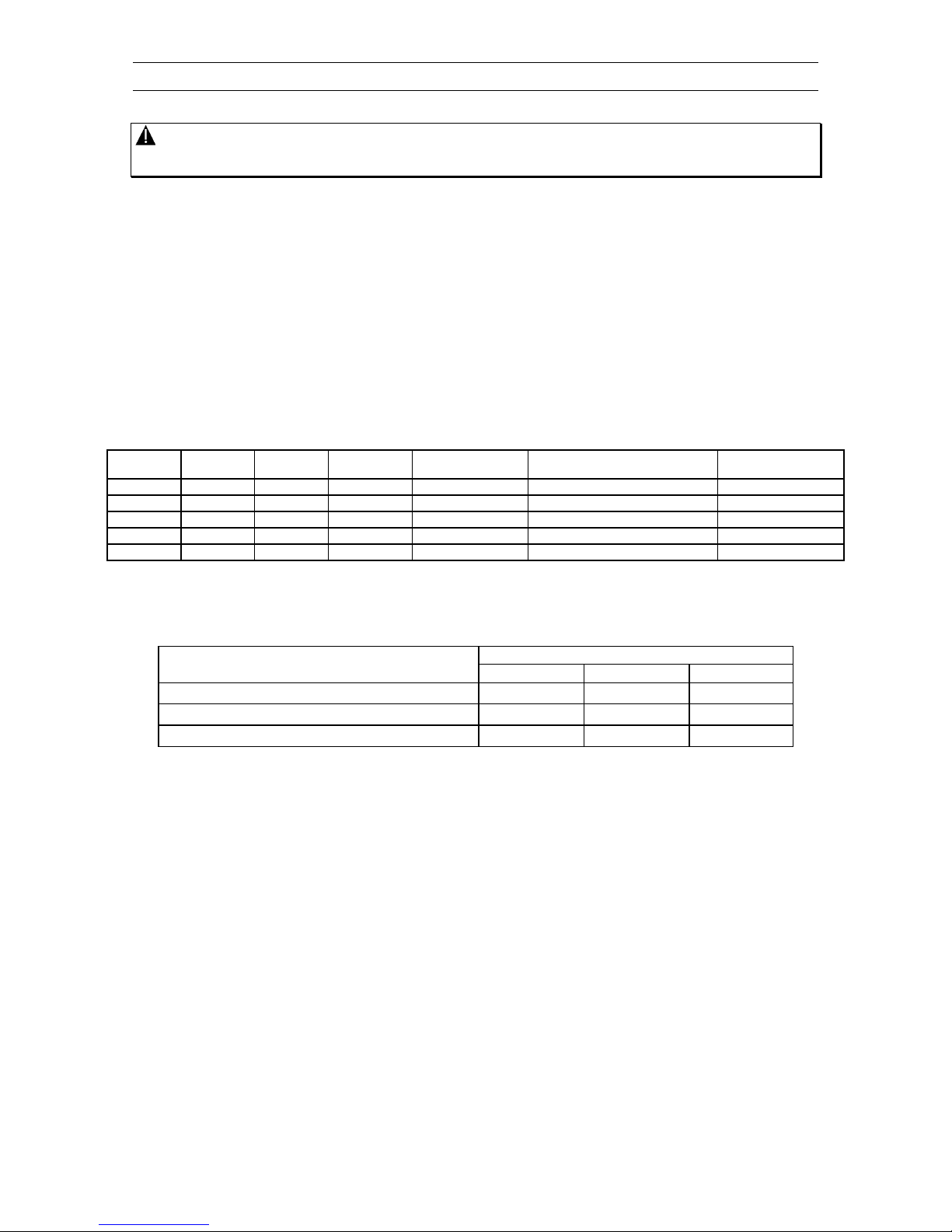
Recommended Coaxial Cable Types
Cable
Type
Belden
Type No.
Alpha
Type No.
West Penn
Type No.
Type Center
Conductor
Type Shield and
% Coverage
DC Resistance
ohms/1000 ft (km)
RG-11/U 8213 9847 811,4811 14 Solid BC BC braid (95%) 2.6 (8.5)
RG-6/U 9248 9804C 806,4806 18 Solid BC Foil + 61% TC braid (100%) 7.5 (24.6)
RG-59/U 8281* ---- 815 20 Solid BC 2 TC braids (96%) 9.9 (32.5)
RG-59/U 9259 9803 816 22 Stranded BC BC braid (95%) 15.0 (49)
RG-59/U 9659 ---- ---- 22 Stranded BC BC braid (95%) 15.0 (49)
*Requires special BNC-M connector due to 0.305 nominal O.D.
Belden Inc. http://www.belden.com/ (800) 235-3361
Alpha Wire Company http://www.alphawire.com/ (800)-52 ALPHA (522-5742)
West Penn Wire http://www.westpenn-cdt.com/ (800)-245-4964
Picture Quality vs. Cable Length
Maximum Cable Run** ft (m)
Picture Quality
RG-59/U RG-6/U RG-11/U
Usable picture 1100 (350) 1500 (450) 2400 (750)
Clean picture 820 (250) 1000 (300) 1600 (500)
Best picture 400 (120) 530 (160) 820 (250)
** For longer cable runs, use a Vicon Video Amplifier to obtain a suitable picture.
Page 13

Vicon Part Number 8009-8170-01-02 Rev 709
12
Vicon Standard Equipment Warranty
Vicon Industries Inc. (the “Company”) warrants your equipment to be free from defects in material and workmanship under
Normal Use from the date of original retail purchase for a period of three years, with the following exceptions:
1. VCRs, all models: Labor and video heads warranted for 120 days from date of original retail purchase. All
other parts warranted for one year from date of original retail purchase.
2. Video monitor CRT (cathode ray tube) and LCD monitors, all models: One year from date of original retail
purchase.
3. Uninterruptible Power Supplies: Two years from date of original retail purchase.
4. VDR-304, VDR-308 and VDR-316 Recorder Series: One year from date of original retail purchase.
5. V5616MUX: One year from date of original retail purchase.
6. S10-CH: 18 months from date of original retail purchase.
7. Normal Use excludes prolonged use of lens and pan-and-tilt motors, gear heads, and gears due to
continuous use of “autopan” or “tour” modes of operation. Such continuous operation is outside the scope of
this warranty.
8. Vicon Security Management Systems (SMS) All Models: All hardware is warranted for two years from date
of original retail purchase.
Date of retail purchase is the date original end-user takes possession of the equipment, or, at the sole discretion of
the Company, the date the equipment first becomes operational by the original end-user.
The sole remedy under this Warranty is that defective equipment be repaired or (at the Company’s option) replaced,
at Company repair centers, provided the equipment has been authorized for return by the Company, and the return
shipment is prepaid in accordance with policy.
The Company will not be obligated to repair or replace equipment showing abuse or damage, or to parts which in the
judgment of the Company are not defective, or any equipment which may have been tampered with, altered, misused,
or been subject to unauthorized repair.
Software supplied either separately or in hardware is furnished on an “As Is” basis. Vicon does not warrant
that such software shall be error (bug) free. Software support via telephone, if provided at no cost, may be
discontinued at any time without notice at Vicon’s sole discretion. Vicon reserves the right to make changes
to its software in any of its products at any time and without notice.
This Warranty is in lieu of all other conditions and warranties express or implied as to the Goods, including
any warranty of merchantability or fitness and the remedy specified in this Warranty is in lieu of all other
remedies available to the Purchaser.
No one is authorized to assume any liability on behalf of the Company, or impose any obligations on it in connection
with the sale of any Goods, other than that which is specified above. In no event will the Company be liable for
indirect, special, incidental, consequential, or other damages, whether arising from interrupted equipment operation,
loss of data, replacement of equipment or software, costs or repairs undertaken by the Purchaser, or other causes.
This warranty applies to all sales made by the Company or its dealers and shall be governed by the laws of New York
State without regard to its conflict of laws principles. This Warranty shall be enforceable against the Company only in
the courts located in the State of New York.
The form of this Warranty is effective November 25, 2008.
THE TERMS OF THIS WARRANTY APPLY ONLY TO SALES MADE WHILE THIS WARRANTY IS IN EFFECT.
THIS WARRANTY SHALL BE OF NO EFFECT IF AT THE TIME OF SALE A DIFFERENT WARRANTY IS
POSTED ON THE COMPANY’S WEBSITE, WWW.VICON-CCTV.COM. IN THAT EVENT, THE TERMS OF THE
POSTED WARRANTY SHALL APPLY EXCLUSIVELY.
Vicon Part Number: 8006-9010-03-06 Rev 1108
Page 14
Vicon Part Number 8009-8170-01-02 Rev 709
13
Vicon Industries Inc.
Corporate Headquarters
89 Arkay Drive
Hauppauge, New York 11788
631-952-CCTV (2288) 800-645-9116
Fax: 631-951-CCTV (2288)
Vicon Europe
Headquarters
Brunel Way
Fareham, PO15 5TX
United Kingdom
+44 (0) 1489 566300
Fax: +44 (0) 1489 566322
Germany
vin-videotronic infosystems gmbh
Lahnstrasse 1
D-24539 Neumuenster
Phone: +49 (0) 4321 8790
Fax: +49 (0) 4321 879 47
Far East Office
Unit 5, 17/F, Metropole Square
2 On Yiu Street, Shatin
New Territories,
Hong Kong
(852) 2145-7118
Fax: (852) 2145-7117
Internet Address: www.vicon-cctv.com
 Loading...