

Page 1
Vicon Industries Inc. does not warrant that the functions contained in this equipment will
XX292-20-00
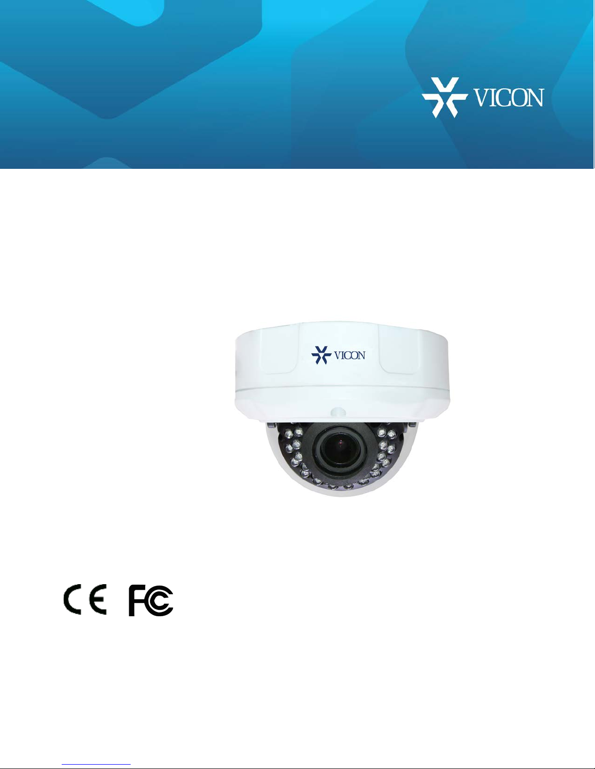
V940D
Quick Guide
Network Dome Camera
meet your requirements or that the operation will be entirely error free or perform precisely
as described in the docu mentation. This system has n ot been designed to be used in
life-critical situat ions and must not be used for this purpose.
Document Number: 8009-8292-20-00 Product spe cifications subject to change without notice.
Issued: 7/17 Copyright © 2017 Vicon Industries Inc. All rights reserved.
Tel: 631-952-2288) Fax: 631-951-2288
Vicon Industries Inc.
Toll Free: 800-645-9116
24-Hour Technical Support: 800-34-VICON
(800-348-4266) UK: 44/(0) 1489-566300
www.vicon-security.com
Page 2
WARNING
may not cause harmful interference, and (2) this device must accept any interference received, including
or it may hamper telecommunications around.
TO REDUCE THE RISK OF FIRE OR ELECTRIC S HOCK, DO N O T EXPOS E THIS PRODUCT TO RAIN OR MOISTURE.
DO NOT INSERT ANY METALLIC OBJECTS THROUGH THE VENTILATION GRILLS OR OTHER OPENINGS ON THE
EQUIPMENT.
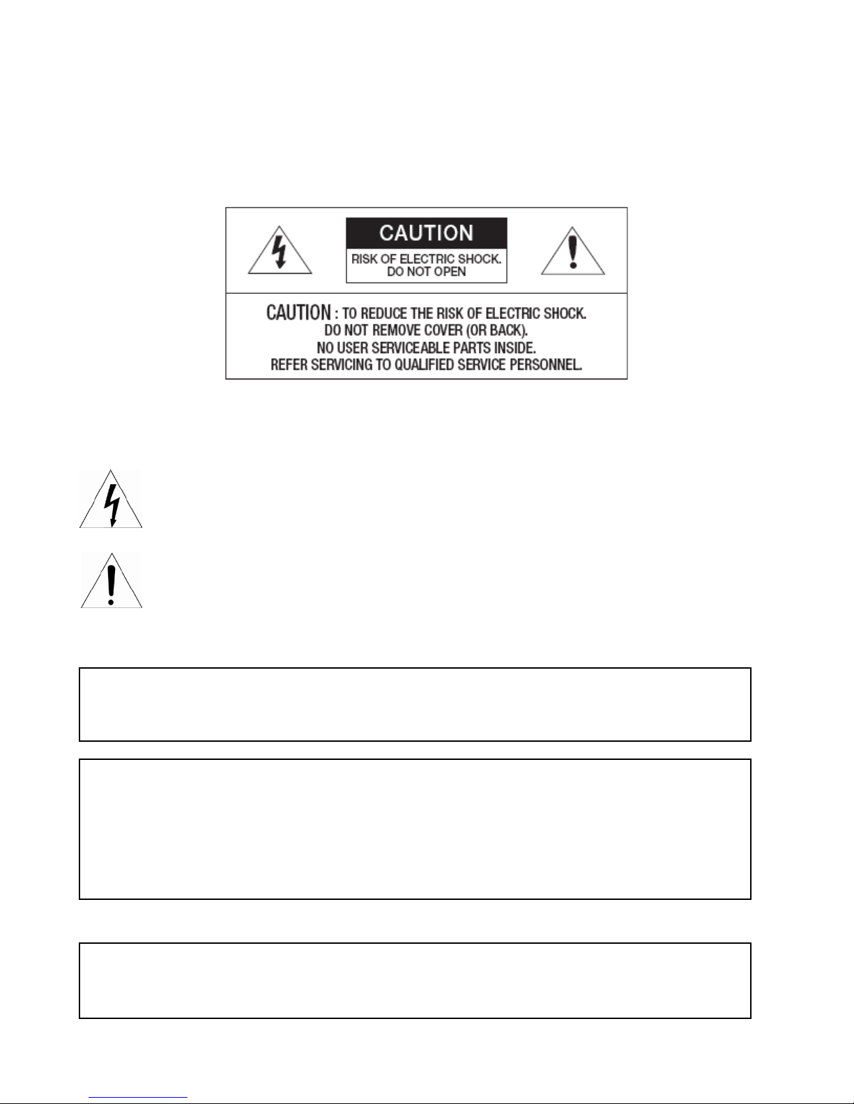
CAUTION
EXPLANATION OF GRAPHICAL SYMBOLS
The lightning flash with arrowhead symbol, within an equilateral triangle, is intended to alert the user
to the presence of unins ulated “dangerous voltage” w ithin the product’s enclosure that m ay be of
sufficient magnitude to constitute a risk of electric shock to persons.
The exclamation point within an equilateral triangle is intended to alert the user to the presence of
important operating and maintenance (servicing) instructions in the literature accompanying the
appliance.
FCC COMPLIANCE STATEMENT
This device complies with the FCC Rules. Operation is subject to the following two conditions: (1) this device
interference that may cause undesired operation.
FCC INFORMATION: This equipment has been tested and found to comply with the limits for a Class A
digital device, pursuant to the FCC Rules. With thes e rules and r egulations bei ng obeyed t o maintain the
good working condition of device, the operation is not supposed to be affected by the external interruptions
under certain circumstances. This device is electromagnetic, so all the installation and application processing
along the device has to follow strictly to the manual
Meanwhile, there is no guarantee that interference will not occur in a certain particular installation situation.
CE COMPLIANCE STATEMENT
WARNING
This is a Class A product. In a domestic environment this product may cause radio interference in whi ch
case the user may be required to take adequate measures.
2
Page 3

3
Read this manual carefully before installation
This manual should be saved for future use.
Important Safety Instructions and Warnings
Electronic devices must be kept away from water, fire or high magnetic radiation.
Clean with a dry cloth.
Provide adequate ventilation.
Unplug the power supply when the device is not to be used for an ex tended period of time.
Only use components and parts recommended by manufacturer.
Position power source and related wires to assure to be kept away from ground and entrance.
Refer to qualified personnel for all service matters.
Save product packaging to ensure availability of proper shipping containers for future transportation.
Indicate that the uninsulated components within the product may carry a voltage harmful to humans.
Indicate operations that should be conducted in strict compliance with instructions and guidelines contained in this manual.
Warning: To avoid risk of fire and electric shock, keep the product away from rain and moisture!
Page 4

4
Introduction
The information in this manual provides quick installation and setup procedures for the V940D series network
cameras. These units should only be installed by a qualified technician using approved materials in
conformance with federal, state, and local codes. Read these instructio ns thoroughly before beginning an
installation. Always refer to Vicon’s website to a ssure you have the most up-to-date manual,
www.vicon-
security.com.
The V940D Series Dome Camera adopts progressive scan CMOS sensor with an internal HD motorized zoom lens.
The camera has an internal Smart IR technology that provides 98 ft/30m IR distance. The IR LEDs output power
can be adjusted automatically according to the brightne ss of the scene so that the IR LEDs do not work at full
capacity. The power consumption of the complete unit is greatly lowered and the service life is lengthened.
V940D Series offers 2MP cameras and 4MP cameras; the 4MP cameras ca n support up to 2 592×1520@20fps
video output. All cameras use H.265/H.264/M-JPEG encoding, providing output with excellent definition and color
reproduction, more detailed and acc ur ate in f ormation an d the accu racy of s mart analys is that can, effectively, be
guaranteed.
V940D Series cameras boast smart functions, including camera tampering, to detect if th e camera/lens has been
moved, blocked, low/high brightness or defocused; in trusion detection, pr oviding protection for key areas; and
line cross detection, providing border protection, which are important features for many enterprises. These
cameras can be widely used in sites that demand high definition image quality in low lighting environments, such
as ordinary buildings, supermarkets, hotels, shops, par ks, schools, factories, warehouses , undergro und parki ng
lots, etc.
The compact design makes it easy to install and provides 3-axis adjustment, for easy adjustment of the
monitoring angle.
System Requirement
Configuration of the computer to display image and control the camera:
CPU: Intel Pentium 4, 2.4 GHz or above
RAM: 512MB or greater
Network Port: 100M Ethernet port
Operating System: Microsoft Windows 10, Windows 7, Windows XP
IE browser version: Microsoft Internet Explorer 8.0 or above
Page 5
5
Installation
For the network camera to oper ate, it is necessary to connect a network cable for
data transmission and power
connection from a power adapter. The unit also has alarm and audio connections.
Installation Precautions
Do not drop the camera or subject it to harsh movement.
Do not point the camera lens directly toward the sun or other strong light.
Do not install the camera in environments with temperature beyond the acceptable range
(-40°F to 140°F/-40°C to 60°C), or with high humidity, direct rainfall, frequent vibrations and shocks.
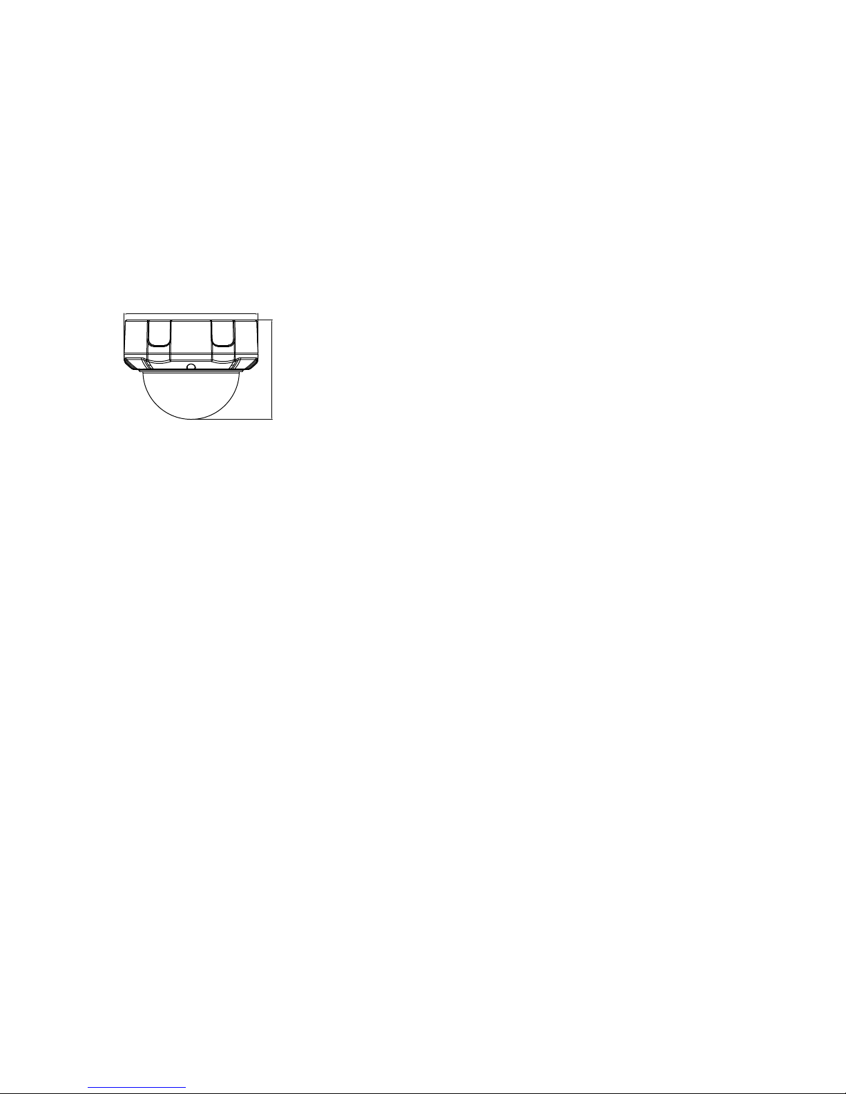
Dimensions
4.02(102.1)
Ø5.43(137.8)
Dimensions Unit: in. (mm)
The camera is supplied with an accessory kit that includes mounting hardware (screws, anchors and
grommets), an RJ-45 connector protective cover, a power connector (2-pin screw terminal), replacement/spare
locking screws (screws that secure the camera module in its cradle), a BNC cable connector that allows
connection of spot monitor and an Allen tool to loosen the screws.
Page 6
6
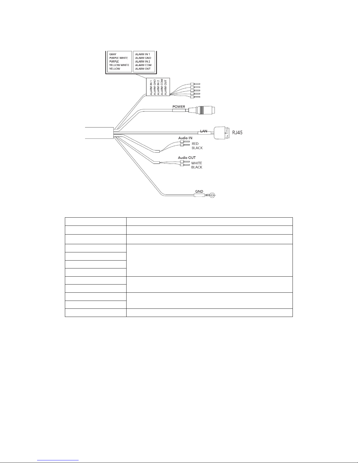
Cable Connections
Item
Description
LAN RJ-45
Ethernet, RJ-45 port compatible with 10/100Mbps PoE modular jack
Power
Standard adapter jack for 12 VDC or 24 VAC
Alarm In
Alarm input and output, 5
-pin terminal
GND
Alarm Out
Alarm COM
Audio In
Audio input,
2-pin terminal; line-level microphone
GND
Audio Out
Audio output, 2
-pin terminal; amplified speaker
GND
GND
Ground
(Black is GND)
Page 7
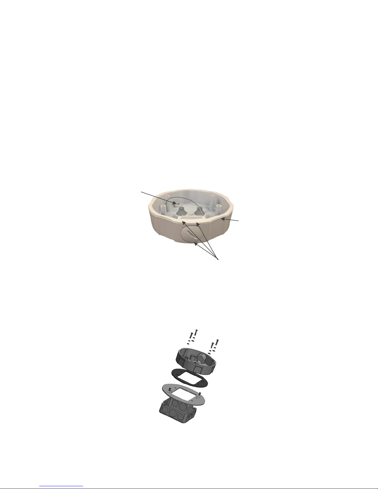
Installing & Adjusting Camera
Cable access holes (3X)
Standoffs for camera
Mounting holes (3X)
Select a location that is cle a r of obsta cles and can support the we ig ht of t he unit. E xercise ma ximum cautio n w hen
installing the unit to the wall or ceiling the unit falling can result in injuries and accidents. As a failsafe against falling,
attach the unit by chain, wire cable or other safety restraint to an appropriate anchor point.
Step 1: Prepare th e mounting holes
To provide f or cable management, th e camera can be mounted to a bac k box, model V940D-BOX or using an adapter
plate to allow mounting to a 4x4 electrical box, model V940-PLATE.
Note: Ma ke s ur e there is room for a cable routing hole at the location and drill a hole to route the cables. Cabling
should be routed to the installation location.
The V940D-BOX is supplied with a mounting te mplate and hardware necess ary to mount it. Using the mounti ng
template, prepare the three mounting holes. Se cure t he box to t he surface using the scre ws and an chors s upplie d
or hardware appropriate f or the moun ting surf ace. There are th ree cable ac cess holes pro vided, one on the side and
two on the rear. Route the cables through one of these access holes.
mounting (4X)
Loosen the three screws on the clear dome assembly to remove the clear bubble. Note that there is a bag of desiccant
inserted in the camera assembly; do NOT remove this. Secure the camera dome to the standoffs in the back box
using the screws and washers provided in the accesso r y kit.
The V940-PLATE can be used to mount the camera dome to a standard 4x4 electrical box. Refer to the drawing
below.
7
Page 8
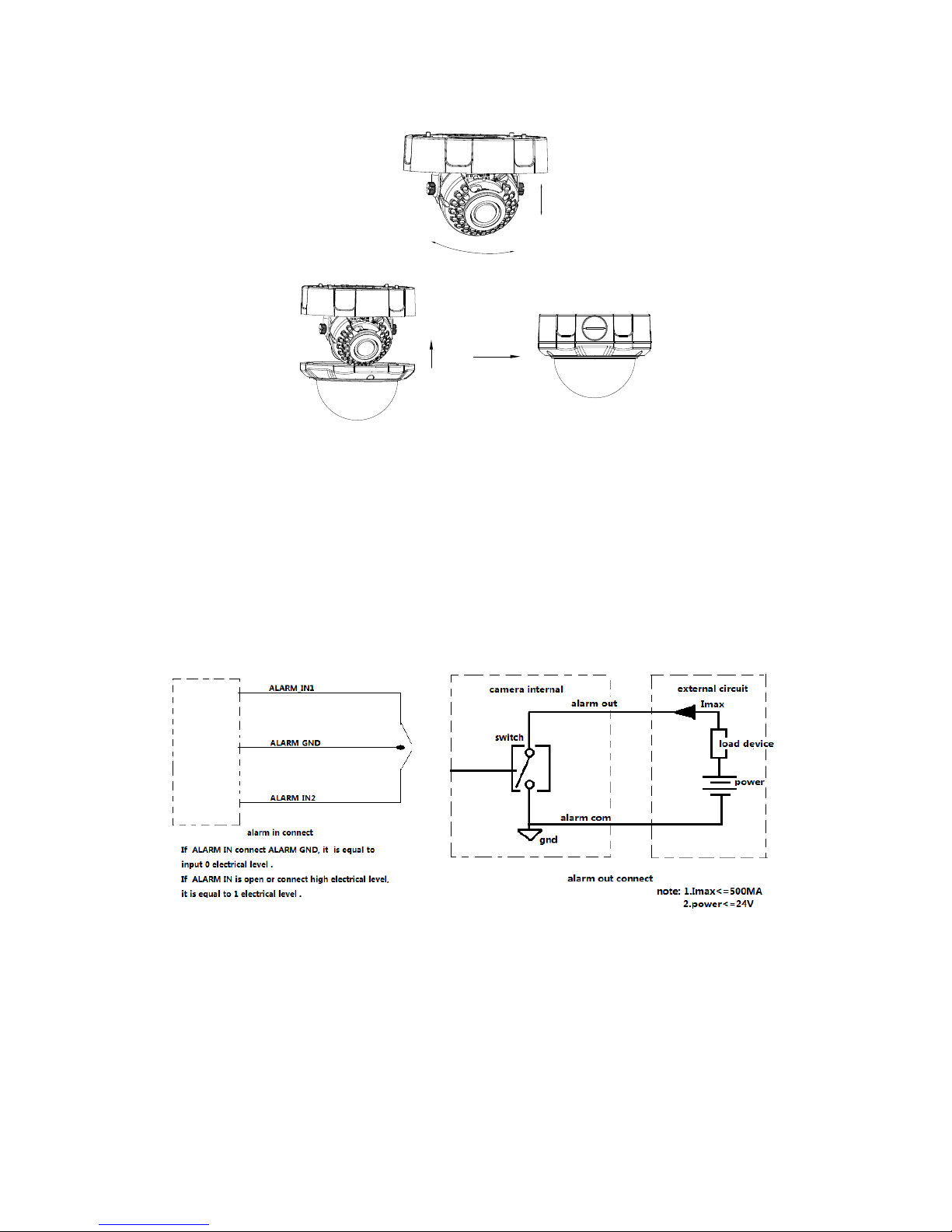
Step 3: Adjust the camera angle
Loosen the locking screws, adjust the camera angle and direction to the desired position and then tighten the screws.
Re-install the clear dome assembly to the camera and secure with the screws.
Connections
Connecting to the RJ-45
Connect a standard RJ-45 cable to the network port of the network camera. Generally a cross-over cable is used for
direct connection to PC, while a direct cable is used for
(Power over Ethernet) to
supply power to the camera. An RJ-45 connector protective cover is supplied in the
accessory kit to protect the connection.
connection to a hub. You can also use a router featuring PoE
Connecting Alarms
There are two dry contact alarm inputs and one alarm outp ut provided; the alarm output acts as a switch to drive
an external device, such as a light. R efer to the figures below for connection and utilization of alarm input/output.
Be sure to follow the current limits noted in the diagrams.
Connecting the Power
Connect the power for the network camera, 24 VAC or 12 VDC. For 12 V DC, connect the positive (+) pole to the
‘+’ position and the negative (-) pole to the ‘-’ position for the DC power.
–
Be careful not to reverse the polarity when connecting a 12 VDC power cable.
–
A router featuring PoE (Power over Ethernet) can also be used to supply power to the camera.
Connecting Audio
There is one audio input and one audi o output. Connect an external line level Mic to Audio input and a Speaker to
Audio output.
8
Page 9
Network Connection and IP Assignment
The network camera is designed for use on an Ethernet network and requires an IP address for access. Most
networks today have a DHCP server that automatically assigns IP addresses to connected devices. By the factory
default, your camera is set to obtain the IP address automatically via DHCP server. If your network does not have
a DHCP server the camera will us a link local IP, i.e. 169.254.x.x.
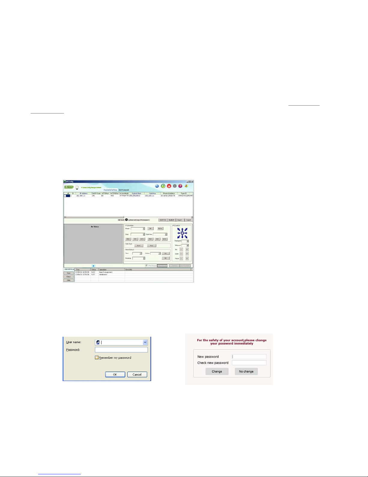
If DHCP is enabled and the product cannot be accessed, run the Discovery Tool utility to search for and allocate an
IP address for the camera. The Discovery Tool (IPCConfig.exe) can be found on Vicon’s website,
security.com, on the Software Downloads p age for Vicon cameras.
Note: The approved browser for the camera is Internet Explorer*.
Depending on the version of Windows and IE, your screens may be slightly different but similar in function.
Connect the network camera to the network and power up.
Start IPCConfig. The main window displays and the devices connected to the network will display. Right click on the
camera IP to open a browser. A login will display.
(1) Login
Enter user name and password in the p op-up login inte rface. For first time users, the default admin login is ADMIN
(case sensitive; password: 1234). For increased security, it is recommended to change the password. After a
successful login, a screen will display to change the password; this can be done here or using the Settings, Users
screen. Select Change or No change. If no change is selected you will open the Live camera interface.
*Supports Internet Explorer 8.0 or above, however, IE 10 or above is required for full functionality, including the file upgrade function.
www.vicon-
9
Page 10
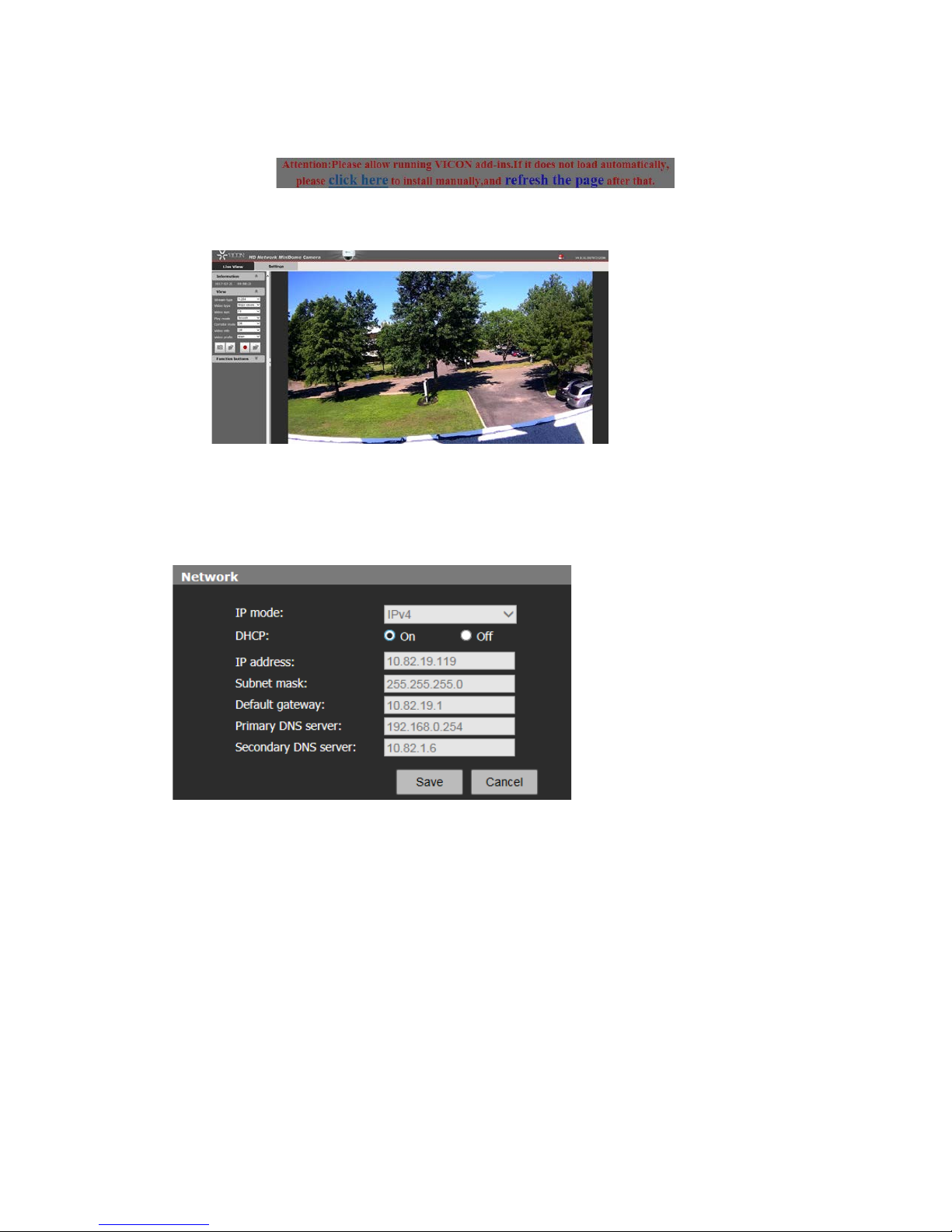
(2) Install control
You ma y b e prompted to allo w running a Vicon add-in. Click to install man ually and run the add-in. Follow the
prompts.
Live View interface displaying the major stream at H.264 format:
Click the Settings t ab and select Network. On this page (below), select Off to turn off DHCP. Then enter the
required IP address, Subnet mask and Default gateway. DNS server is not required. Click Save and restart device.
Click Yes and exit IPCConfig.
10
Page 11
Live View Page
From the Live View page, users can select Stream Type, Video Type, Video Size, Play Mode, Corridor Mode, Video
Info, Video Profile, Snapshot and Local recording can be configured. From here, the Settings screens can be
accessed by the admin.
Function Buttons
Indicate audio input/output are disabled. Click the buttons to enable audio input/output; the buttons will be
shown as .
Indicate that the motion detection and privacy mask functions are disabled. Click the buttons to enable them;
the buttons will be shown as .
Indicates that the intelligence functio ns are disabled. Click the button to enable them; the button will be
shown as 。
Note: The motion detection and p rivacy ma sk se tti ngs ca n only be set in the Live view settings interface when they
are enabled in the Audio & Video Settings.
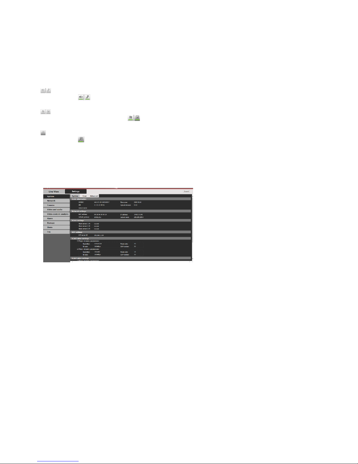
Click the option tab “Settings” to enter the system Settings interface.
From the Settings tab, a n admin has access to all the configuration screens: System, Network, Camera, Video and
audio, Alarm, Storage, Users and Log.
11
Page 12

For ofce locations, visit the website: www.vicon-security.com
VICON INDUSTRIES INC.
 Loading...