


ViconNet 8.0 Software
XXYYY-XX-XX
Vicon Industries Inc. does no t warr ant th at th e fu nct ions co n ta ined in th is eq uipm ent wi ll
XX289-40-00
V9360-6 and V9360-12 Series
Programming Guide
Network Panoramic Cameras
meet your requirements or that the operation will be entirely error free or perform
precisely as described in the documentation. This system has not been designed to be
used in lif e-critical situations and must not be used for this purpose.
Document Number: 8009-8289-40-00 Product spec ifications subject to change without
notice. Issued: 2/17 Copyright © 2017 Vicon Industries Inc. All rights reserved.
Vicon Industri es In c.
Tel: 631-952-2288) Fax: 631-951-2288
Toll Free: 800-645-9116
24-Hour Technical Support: 800-34-VICON
(800-348-4266) UK: 44/(0) 1489-566300
www.vicon-security.com

1
Table of Contents
1. Overview ................................................................................................................................ 4
2. Menu Tree .............................................................................................................................. 4
2.1 Home Page.................................................................................................................. 5
2.1.1 Function Items on Home Page ..................................................................... 5
2.1.2 Function Differences among Models .......................................................... 10
2.2 System ...................................................................................................................... 12
2.2.1 System ....................................................................................................... 12
2.2.2 Security ...................................................................................................... 14
2.2.3 Network ...................................................................................................... 22
2.2.4 DDNS ......................................................................................................... 30
2.2.5 Mail ............................................................................................................ 30
2.2.6 FTP ............................................................................................................ 31
2.2.7 HTTP .......................................................................................................... 31
2.2.8 Events (Alarm Settings) .............................................................................. 32
2.2.9 Storage Management ................................................................................. 58
2.2.10 Recording ................................................................................................... 62
2.2.11 Schedule .................................................................................................... 63
2.2.12 File Location (Snapshots and Web Recording) ........................................... 65
2.2.13 View Informat ion ........................................................................................ 65
2.2.14 Factory Default ........................................................................................... 67
2.2.15 Software Version ........................................................................................ 67
2.2.16 Software Upgrade ...................................................................................... 68
2.2.17 Maintenance ............................................................................................... 69
2.3 Streaming .................................................................................................................. 70
2.3.1 Video Format (Video Resolution and Rotate Type) ..................................... 71
2.3.2 Video Compression .................................................................................... 73
2.3.3 Video OCX Protocol ................................................................................... 74
2.3.4 Video Frame Rate ...................................................................................... 74
2.3.5 Audio (Audio Mode and Bit Rate Settings) ................................................. 75
2.4 Camera ...................................................................................................................... 77
2.4.1 Exposure .................................................................................................... 77
2.4.2 White Balance ............................................................................................ 80
2.4.3 Picture Adjustment ..................................................................................... 83
2.4.4 IR Function ................................................................................................. 84
2.4.5 Noise Reduction ......................................................................................... 85
2.4.6 Profile ......................................................................................................... 87
2.4.7 Backlight .................................................................................................... 88
2.4.8 Digital Zoom ............................................................................................... 88
2.4.9 WDR Function ............................................................................................ 89

2
2.4.10 Fisheye Setting (Fisheye IP Camera Only) ................................................. 90
2.4.11 TV System.................................................................................................. 93
2.5 Pan Tilt ...................................................................................................................... 94
2.5.1 Preset ......................................................................................................... 94
2.5.2 Sequence ................................................................................................... 95
2.5.3 Pan/T ilt Control .......................................................................................... 96
2.6 Logout ....................................................................................................................... 97
Appendix A: Install UPnP Components..................................................................................... 98
Appendix B: IP Addresses from Decimal to Binary .................................................................. 99
Appendix C: Video Resolution ................................................................................................. 100
Primary Video Resolution .................................................................................................... 100
Quad Streams ......................................................................................................... 100
Triple Streams ......................................................................................................... 105
Dual Streams ........................................................................................................... 108
Single Stream .......................................................................................................... 109
Advanced Video Resolution ................................................................................................ 110
Quad Streams ......................................................................................................... 110
Triple Streams ......................................................................................................... 123
Dual Streams ........................................................................................................... 126
Single Stream .......................................................................................................... 128
Single Stream- 2M Only ........................................................................................... 128
Primary- HDR (2 Shutter Mode) Video Resolution............................................................... 129
Triple Streams- 4M Only .......................................................................................... 129
Dual Streams- 4M Only ........................................................................................... 133
Single Stream- 4M Only ........................................................................................... 134
Triple Streams- 3M Only .......................................................................................... 134
Dual Streams- 3M Only ........................................................................................... 139
Single Stream- 3M Only ........................................................................................... 139
Advanced- HDR (2 Shutter Mode) Video Resolution ........................................................... 140
Triple Streams- 4M Only .......................................................................................... 140
Dual Streams- 4M Only ........................................................................................... 145
Single Stream- 4M Only ........................................................................................... 146
Triple Streams- 3M Only .......................................................................................... 146
Dual Streams- 3M Only ........................................................................................... 149
Single Stream- 3M Only ........................................................................................... 150
Advanced- HDR (3 Shutter Mode) Video Resolution ........................................................... 151
Triple Streams- 4M Only .......................................................................................... 151
Dual Streams- 4M Only ........................................................................................... 156
Single Stream- 4M Only ........................................................................................... 157
Triple Streams- 3M Only .......................................................................................... 157
Dual Streams- 3M Only ........................................................................................... 161

3
Single Stream- 3M Only ........................................................................................... 161
12M Fisheye IP Camera...................................................................................................... 162
Dual Streams- Front End Correction ........................................................................ 162
Single Stream- Front End Correction ....................................................................... 162
Quad Streams- Back End Correction ....................................................................... 163
Triple Streams- Back End Correction ....................................................................... 168
Dual Streams- Back End Correction ........................................................................ 170
Single Stream- Back End Correction ....................................................................... 171
6M Fisheye IP Camera ....................................................................................................... 172
Dual Streams- Front End Correction ........................................................................ 172
Single Stream- Front End Correction ....................................................................... 172
Quad Streams- Back End Correction ....................................................................... 173
Triple Streams- Back End Correction ....................................................................... 178
Dual Streams- Back End Correction ........................................................................ 180
Single Stream- Back End Correction ....................................................................... 180
5M Fisheye IP Camera Video Resolution ............................................................................ 181
Dual Streams- Front End Correction ........................................................................ 181
Single Stream- Front End Correction ....................................................................... 181
Quad Streams- Back End Correction ....................................................................... 182
Triple Streams- Back End Correction ....................................................................... 192
Dual Streams- Back End Correction ........................................................................ 195
Single Stream- Back End Correction ....................................................................... 196

4
1. Overview
The V9360-6 and V9360-12 Series Panoramic IP Cameras are provided with a
user-friendly browser-based configuration interface and a free bundled CMS
(Central Management System) for video playback an d recording . In thi s manual,
information about main page introduction, system related settings and camera
settings will be described in detail.
2. Menu Tree
There are six main tabs including <Home>, <System>, <St reaming>, <Camer a>,
<Pan Tilt> and <Logout> on the Home Page.
Home
Users can monitor the live video of the targeted area.
System Setting
The administrator can set host name, system time, root password, network
related settings, etc. Further details will be explained in the System chapter.
Streaming Setting
The administrator can configure video f ormat, video compression, video OCX
protocol, video frame rate and audio compression in this page.
Camera Setting
This setting page is only available for the administrator and user accounts that
have camera con trol privileges. T h e administrator and users can adjust various
camera parameters including Exposure, White Balance, Sharpness, 2D/3DNR,
Digital Zoom, WDR, etc.
Pan/Tilt Setting
This setting page is only available for the administrator and user accounts that
have camer a control privileges. The administrator and user s can set pr eset point
and sequence line in this page. However, only the administrator can access the
<Pan/Tilt Control> setting to activate the pan/tilt function and select the RS-485
protocol.
NOTE: Pan/Tilt function is only available for camer a models with RS-485.

5
Logout
Click on the tab to re-login to the camera with another userna me a nd pas sword.
2.1 Home Page
Click on the tab <Home> to access the <Home> Page. There are several
function buttons on this page. Detailed information of each item is described in
the following section.
NOTE: The function buttons on the Home page will vary according to
different camera models.
2.1.1 Function Items on Home Page
Multiple Languages Support
Multiple languages are supported, including German, English, Spanish, French,
Italian, Japanese, Portuguese, Russian, Simplified Chinese and Traditional
Chinese for the viewer window interface.
Display Stream Selection
According to the streaming setting, users can choose the one stream to display
from the drop-down list.

6
Zoom Adjustment (Motorized Lens Models Only)
Wide / Tele buttons
Hold the <WIDE / TELE
> button and implement continuous zoom
adjustment. This functi on is only available for models with zoom lens.
Wide / Tele Steps buttons
Select a Tele / Wide step value from the drop-down menu to shift the
zoom lens according to the define value.
Reset button
Click on the <Reset> but ton a nd the z oo m len s w ill be calibr at ed to t he
maximum wide end.
Manual Focus Adjustment (ABF Box IP Camera and Motorized Lens Models
Only)
Near / Far buttons
Hold the <Near / Far> button and implement continuous focus
adjustment. This function is also available for models with zoom lens.
Near / Far Steps buttons
Select a Tele / Wide step value from the drop-down menu to shift the
focus lens according to the defined value.
Reset button
Click on the <Reset> button and the focus lens will first be reset to the
maximum near end. Then the lens will be calibrated
to a suitable
position according to the monitoring environment.
Auto Focus (AF) Adjustment (Zoom Lens Models and Motorized Lens
Models Only)
Manual button
Click on the <Manual> button and users can adjust the focus manually
via the <Near / Far> buttons.
Zm Trig (Zoom Trigger AF)
In this mode, AF is activated every time when zoom is adjusted.
Push AF
The One Push AF function is for fixing the focus in one click. This
function is also available for ABF Box IP Camera.

7
Precise AF Button (ABF Box IP Camera only)
This function is to precisel y adjust t he f ocus continuously and to prevent
the camera from being out of focus. Check this item before pressing the
<Push AF> button.
Lock
(ABF Box IP Camera only)
The Lock function is to lock the ABF function of the Box camera after
the auto focus is adjusted to the best position.
This function is us ed to prev ent the camera from being out o f focus when
the camera is moved afterwards or is accidentally adjusted locally or
remotely via NVR/VMS.
Click on this button to lock the ABF function of
the camera. Click again to disable this function and adjust the focus of
the camera.
Fisheye Image Adjustment (Panoramic IP Camera Only)
Fisheye Source Image
Click on the <Fishey e S ourc e I mag e> button to view the live videos as
hemisphere fisheye source images.
Single ePTZ
Click on the <Single ePTZ> button to view the dewarped live images
and virtually
pan / tilt / zoom the camera according to users’ needs.
Users can implement virtual PTZ
by rotating the mouse wheel (for
zoom in / out), and drag the mouse into any direction.
360° Panoramic
Click on the <360°
Panoramic> button to view the dewarped live
images as two 180° views.
Quad View
Click on the <Quad View> button to view the dewarped live images as
four ePTZ views.
180° Panoramic
For Wall Mount Installed Camera, click on the <180° Panoramic>
button to view the dewarped live video as a single 180° view.

8
Dual ePTZ
For Wall Mount Installed Camera, click on the <Dual ePTZ> button to
view the dewarped live video as a single 180° view with two ePTZ
views. Users can implement virtual
PTZ by rotating the mouse wheel
(for zoom in / out) and drag the mous e in any dir ection i n the e P TZ liv e
video panes.
The available Fisheye Image Adjustment buttons are different according to the
dewarping and installation method selected on the <Fisheye Setting> page. The
following table shows the available buttons in different dewarping methods and
installation methods. The supported buttons are represented by “v”.
Dewarping Method /
Installation Method
Button
Front End Correction*
Back End Correction
Ceiling
Mount
Wall
Mount
Ceiling
Mount
Wall
Mount
Fisheye Source Image
-
-
v
v
Single ePTZ
v** - v
-
360° Panoramic
v - v
-
Quad View
v - v
-
180° Panoramic
- v -
v
Dual ePTZ
- v -
v
*If users use the Front End C orrection method for dewar ping, the butt ons wil l only
be shown when video format is set to H.264-2 or MJPEG on the home page.
**If users use the Front End Correction method , the Single ePTZ button supported
in Ceiling Mount installation is only available when the resolution of the second
stream is smaller than “960 x 960”.
Quality
Click to show/hide the video quality information including bitrate and
compression.
Full Screen
Image display size can be adjusted to full screen. Alternatively, right click on the
Live Video Pane and select <Fullscreen> to go full screen.
To exit full screen mode, users can (1) tap <Esc> on the keyboard; (2) double
click on the Live Video Pane; (3) righ
t click on the Live Video Pane and select
<Normal view>.

9
Talk Button
(On / Off)
Talk function allow s the l ocal s it e to talk to the remote si te. Cl i ck on the button to
switch it to On / Off. Users must select th e suit able trans miss ion m ode u nder this
path: Streaming> Audi o to enable this function.
NOTE: This function is only available for user accounts that have this
privilege allowed by the administrator. Please refer to
Security: Add
user> Talk/Listen for further detail s.
Listen Button
(On / Off)
Click on the <Listen> button to mute / activate the audio. Users must select the
suitable transmission mode under Strea ming> Audio to enabl e thi s funct ion.
NOTE: This function is only available for user accounts that have been
granted this privilege by the administrator. Please refer to Security : Add
user> Talk/Listen for further detail s.
Snapshot Button
Click on
the button and the JPEG snapshots will automatically be saved in the
selected location. The default location for saving snapshots is: C:\. To change
the storage location, refer to section File Location of the n ext chapter for further
details.
NOTE: With Windo ws 7 or Windows 8 operating system, to implement
the Snapshot function, users must run IE as administrator. To run IE as
administrator, right click on the IE browser icon and select “
Run As
Administrator” to launch IE.
Live View Pause / Restart Button
(Pause / Restart)
Click on the <Pause> button to disable video streaming; the live video will be
displayed as black. Press the <Restart> button to show the live video.
Record Button
(On / Off)
Click on the <Record> button a nd t he Live View thr oug h the web browser will be
directly recorded to the specific location on the local hard drive, which could be
configured in the File Location
page. The default storage location for the web
recording is: C:\. Refer to section File Location of the next chapter
for further
details.

10
NOTE: With Windo ws 7 or Windows 8 operating system, to implement
the Web Recording function,
users must run IE as administrator. To run
IE as administrat or, right click on the IE brow ser icon and selec t “Run As
Administrator” to launch IE.
Manual Trigger Button
(On / Off)
Click on the <Manual T rigger > button to turn on and off the manual trigger. Refer
to section Manual T r igg er of the next chapter for further details.
Optical / Digital Zoom Control
In Normal View display mode, users can implement zoom in / out by moving the
cursor to the liv e video pane an d scr olli ng the mous e wheel . Di git al zoom is only
available when the function is activated in <Digital Zoom> page under the
<Camera> tab.
NOTE: Optic al Zoom functio n is only appli cable for 3x Z oom Lens Models .
2.1.2 Function Differences among Models
The table below shows the available function items seen on the home page for
different IP camera models. The first table below lists the applicable lens for
different IP camera models. According to the applied lens, the supported
functions will vary; refer to the tables below for details. In each table, the
applicable lens and the supported function items are marked by “v”.
Applicable Lens for Different IP Camera Models
Hyper IP Camera
Lens
Model
Fixed-
focal
Varifocal
Motorized Zoom CS Mount Fisheye
IR Bullet
-
v
v
- - -
Box / ABF Box
- - -
- v -
Zoom AF Box
- - - v -
-
Fisheye
- - - - -
v
Compact Dome
-
v v v
-
-
Mini Fisheye
- - - - -
v
Mini Rugged Dome
-
v v v
-
-
Mini Dome
v v v
v
-
-

11
Supported Functions for the Applied Lens
Lens
Function
Fixed-
focal
Varifocal
Motorized Zoom
CS
Mount
Fisheye***
Wall
Mount
Ceiling
Mount
Multiple Language
v v v v v v v
Digital Zoom Ctrl
v v v v v - -
Screen Size Adjust
v v v v v v v
Talk (On / Off)*
v v v v v v v
Speaker (On / Off)*
v v v v v v v
Snapshot
v v v v v v v
Video Streaming
Pause/Restart
v v v v v v v
Web Recording
(On / Off)
v v v v v v v
Zoom
Adjust.
Tele/Wide
-
-
v
v
- - -
Tele/Wide
Steps
- -
v
- - - -
Reset
-
- v - - -
-
Manual
Focus
Adjust.
Near/Far
-
-
v v v**
-
-
Near/Far
Steps
- -
v
-
v**
- -
Reset
-
- v -
v**
-
-
Push AF
- - - v - - -
Auto
Focus
Adjust.
Manual
- - - v - - -
Cont.
- - - v - - -
Zm Trig
- - - v - - -
Push AF
-
- v - - -
-
Fisheye Source
Image
- - - - -
v v
Dual ePTZ
- - - - - v -
180° Panoramic
- - - - - v -
Single ePTZ
- - - - -
-
v
360° Panoramic
- - - - -
-
v
Quad View
- - - - -
-
v
*Talk and Speaker functions are optional.
**ABF Box IP cameras support Manual Focus Adjustment function. However,
non-ABF Box IP cameras do NOT support this function.
***The function items for fisheye IP camera models will vary according to
different installati on methods. Two installation methods ar e provided: wal l mount
and ceiling mount installation.

12
2.2 System
Under the tab <System>, the categories are show n as the configure page below.
NOTE: Only Administrator can access the <System> configuration p age.
2.2.1 System
The System setting can be found under the path: System> System.
Host Name
The name is for camera identification. If the alarm function (refer to section
Events) is enabled and is set to send alarm messages by Mail / FTP, the host
name entered here will be displayed in the alarm message.
Time Zone
Select the time zone from the drop-down menu according to the location of the
camera.
Enable Daylight Saving Time
To enable DST, please check the item and then specify the time offset and the
DST duratio n. The format for time of fset is [hh:mm:ss]; for ins tance, if the amount
of time offset is one hour, please enter “01:00:00” into the field.
13
Time format
Choose a time format (yyyy/mm/dd or dd/mm/yyyy) from the drop-down menu.
The format of the date and time displayed above the live video window will be
changed according to the selected format.
Sync with Computer Time
Select the item, and v ideo date and time display will synchronize with the PC’s.
NOTE: Users MUST click on the <Save> button to confirm the setting.
Otherwise, the time will not be synced.
Manual
The administrator can set video date and time manually. Entry format should be
identical with the examples shown next to the enter fields.
Sync with NTP Server
Network Time Protocol (NTP) is an alternate way to synchronize the camera’s
clock with a NTP server. Please specify the server that is wished to synchronize
in the entry field. Then select an update interval from the drop-down menu.
For further information about NTP, please see the web site: www.ntp.org.
NOTE: The sync hronization w ill be done ev ery time the camera boot s up.
Click on <Save> to confirm the setting.

14
2.2.2 Security
The Security setting can be found under this path: System> Security.
Click on the <Security> category, there will be a drop-down menu with tabs
including <User>, <HTTPS>, <IP Filter>, and <IEEE 802.1X>.
2.2.2.1 User
The User setting can be found under this path: System> Security> User.
Admin P assword
This item is for the administrator to reset password. Enter the new password in
<Admin password> and <Confirm password>. The maximum length is 14
characters. The input character s / numbers w ill be dis pl ay ed as dots for securi ty
purposes. Click on <Save> to confirm the changes. After the changes are
confirmed, the web browser will ask the administrator to re-login to the camera
with the new password.
NOTE: The following characters are valid: A-Z, a-z, 0-9, !#$%&’-.@^_~.
Add User
This item is for the administrator to add new users. Enter the new user’s name
in <User name> and th e passw or d in <U ser p assw or d>. Username can be up t o
16 characters, and the maximum length of the password is 14 characters. Tick
the boxes below to give privileges for functions, including “Camera control”,
“Talk” and “Listen”. Click on <Add> to add the new user. The name of the new
added user w ill be di spl ay ed in t he <User name> drop-down list under <Manage
User>. There is a maximum of twenty user accounts.
I/O access
This item supports fundamental functions that enable users to view the
live video when accessing to the camera.
Camera control
This item allows the appointed user to change camera paramet ers on the
<Camera> and <PTZ> setting page.

15
Talk/Listen
This item allows the appointed user in the local site (camera site) to
communicate with, for instance, the administrator in the remote site.
Manage User
Delete user
Pull down the <User n ame> drop-down list and select the usern ame that
is wished to be deleted. Click on <Delete> to r emove t he select ed name.
Edit user
Pull down the <User name> drop-down list and select the username.
Click on <Edit> and a popup w indow will appe ar. In the appeared window,
enter the new user password and reset the privileges. Click on <Save>
to confirm the changes. Then click on <Close> to complete the editing.
HTTP Authentication Setting
This setting allows secured connections between the IP camera and web
browser by enforcing access controls to web resources. When users approach
to the web browser, it’ll ask for username and password, which protects the
camera settings or live streaming information from snooping. There are two
security models available: Basic and Digest. Refer to the descriptions below for
more details.
Basic
This mode can only provide basic protection for the connection security.
There will still be risks for the password being intercepted.
Digest
Digest mode is a safer option for protection. The password is sent in an
encrypted format to prevent it from being stolen.
NOTE: Users MUST click on the <Save> button to apply the setting.

16
Streaming Authentication Setting
This setting prov ides securi ty ag ainst unauth oriz ed users fro m getti ng streaming
via Real Time Stre aming Protoc ol (R TSP). If the se tting is en abled , users w i ll be
requested to enter user name and password before viewing the live streams.
There are three security modes available: Disable, Basic and Digest. Refer to
the descriptions below for more details.
Disable
If disable mode is selected, there will be no security provided to against
unauthorized access. Users will not be asked to input user name and
password for authentication.
Basic
This mode can only prov ide basic pr otectio n for t he live s treams. There
will still be risks for the password being intercepted.
Digest
Digest mode is a safer option for protection. The password is sent in an
encrypted format to prevent it from being stolen.
NOTE: Users MUST click on the <Save> button to apply the setting.

17
2.2.2.2 HTTPS
The HTTPS setting can be found under this path: System> Security> HTTPS.
<HTTPS> allows s ecure connections between the cam era and the web browser
using <Secure Socket Lay er ( SSL)> or <Transport L ay er Secur ity (T LS)> , w hich
ensure camera settings or Username / Password info from snooping. It is
required to install a self-signed certificate or a CA-signed certificate for
implementing HTTPS.
To use HTTPS on the camera, an HTTPS certificate must be installed.
The HTTPS certificate can be obtained by either creating and sending a
certificate request t o a Certificat e Authori ty (CA) or cr eating a self-signed H TTPS
certificate, as described below.
Create Self-signed Certificate
Before a CA -issued certificate is obtained, users can create and install a selfsigned certificate firs t.
Click on <Create> under “Create self-signed certificate” and provide the
requested information to install a self-signed certificate for the camera.
Please refer to the las t par t of this section Prov i de the C er ti fica t e In formation for
more details.
NOTE: The self-signed certificate does not provide the same high level
of security as when using a CA-issued certificate.
Install Signed Certificate
Click on the <Create Certificate Request> button to create and submit a
certificate request in order to obt ai n a sig ned cer ti ficate from CA.
Provide the reques t infor mation in the creat e dial og. Pleas e ref er to the follow ing
section Provide the Certificate Information for more details.
When the request is c o mplete, th e s ubject of t he Cr eate d Req ues t w ill be show n
in the field. Click on <Properties> below the Subject field, copy the PEMformatted request and send it to the selected CA.
When the signed certificate is returned, install it by uploading the signed
certificate.

18
Provide the Certificate Information
To create a Self-signed HTTPS C ertificate or a Certi ficate Reques t to CA, pleas e
enter the information as requested.
Create Self Signed Certificate
Create Certificate Request
Country
v
v
State or Province
v
v
Locality
v
v
Organization
v
v
Organizational Unit
v
v
Common Name
v
v
Valid Days
v
-
Country
Enter a two-letter combination co de t o indic at e the c ountr y the certificate
will be used in. For instance, type in “US” to indicate United States.
State or province
Enter the local administrative region.
Locality
Enter other geographical information.
Organization
Enter the name of the organization to which the entity identified in
“Common Name” belong s.
Organization Unit
Enter the name of the organizational unit to which the entity identified in
“Common Name” belongs.
Common Name
Indicate the name of the person or other entity that the certificate
identifies (often used to identify the website).
Valid days
Enter the period in days (1 to 9999) to indicate the valid period of
certificate.
Click on <OK> to save the Certificate Information after completing the setting.

19
2.2.2.3 IP Filter
The IP Filter setting can be found und er thi s path: Syst em> S ecur ity> IP Filt er.
With IP Filter, users can allow or deny specific IP addresses from accessing the
camera.
Enable IP Filter
Check the box to enable the IP Filter function. Once enabled, the listed
IP addresses (IPv4) in the <Filtered IP A ddresses> list box will be allowed
/ denied to access the camera.
Select <Allow> or <Deny> from the drop-down list and click on the
<Apply> button to deter mine the I P filter behavior.
Add IP Address
Input IP address at the blank space below the <Filtered IP Address> list
and click <Add>. The newly-added address will be shown in the list. Up
to 256 IP address entries can be specified.
In addition, to filter a group of IP addres ses, enter an address at the blank
space followed with a slash and a number ranging from 1 to 31, e.g.
192.168.2.81/30. The number after the slash can define how many IP
addresses will be filtered. For details, please refer to the following
example.
Example: Filtering a group of consecutive IP addresses
The steps below show what will be filtered when 192.168.2.81/30 is
entered.
Step 1: Convert 192.168.2.81 to binary numbers. The binary
numbers are 11000000.10101000.00000010.01010001. Users can
refer to Appendix B: IP Addresses from Decimal to Binary for
converting the IP addresses to binary numbers. The number “30”
after the slash is referring to the f irst 30 digits of the binary numbers.
Step 2: Convert a few IP ad dresses befor e and a fter 192. 168.2. 81 to
binary numbers. Then compare their first 30 digits with the binary
numbers of 192.168.2.81.

20
a. Convert 192.168.2.80 to binary numbers. The binary numbers
are 11000000.10101000.00000010.01010000. The first 30
digits are the same with the binary numbers of 192.168.2.81,
thus 192.168.2.80 wil l be filter e d.
b. Convert 192.168.2.79 to binary numbers. The binary numbers
are 11000000.10101000.00000010.01001111. The first 30
digits are different with the binary numbers of 192.168.2.81,
thus 192.168.2.79 will not be filtered. This also means the IP
addresses before 192.168.2.79 will not be filtered. Therefore,
users can stop converting the IP addresses before
192.168.2.79 to binary numbers.
c. Repeat the same procedure in “a” with the IP addresses after
192.168.2.81. Stop when the situation occurs in “b” happened.
Namely, the 30th digit of the binary numbers of IP address
192.168.2.84 is different, and will not be filtered.
As a result, the IP addresses 192.168.2.80 to 192.168.2.83 will be
filtered when entering 192.168.2.81/30. The following table clearly
shows the 30th digit of the binary numbers of IP addresses
192.168.79 and 192.168.84 are different from the others. Therefore,
these two IP addresses will not be filtered.
IP Addresses
Binary Numbers
192.168.2.79
11000000.10101000.00000010.01001111
192.168.2.80
11000000.10101000.00000010.010100
00
192.168.2.81
11000000.10101000.00000010.01010001
192.168.2.82
11000000.10101000.00000010.010100
10
192.168.2.83
11000000.10101000.00000010.01010011
192.168.2.84
11000000.10101000.00000010.01010100
Delete IP Address
To remove an IP address from the <Filtered IP Address> list, please
select the address and click on <Delete>.

21
2.2.2.4 IEEE 802.1X
The IEEE 802.1X setti ng can be found under this path: System> Security> IEEE
802.1X.
The camera is allowed to access a network protected by 802.1X/EAPOL
(Extensible Authenti cation Protocol over LAN).
Users need to contac t with the netw ork administrator for gaining cert ificates, user
IDs and passwords.
CA Certificate
The CA certificate is created by the Certification Authority for the purpose of
validating itself. Upload the certificate for checking the server’s identity.
Client Certificate / Private Key
Upload the Client Certificate and Private K ey for authentic ating the camera i tself.
Settings
Identity
Enter the user identity associated w ith the certi ficate. Up to 16 c haracters
can be used.
Private Key Password
Enter the password (maximum 16 characters) for user identity.
Enable IEEE 802.1X
Check the box to enable IEEE 802.1X.
Click on <Save> to save the IEEE 802.1X/EAP- TLS setting.

22
2.2.3 Network
The Network setting can be found under this path: System> Network.
Click on the <Network> category, there will be a drop-down menu with tabs
including <Basic>, <QoS>, <SNMP>, and <UPnP>.
2.2.3.1 Basic
The Basic setting can be found under this path: System> Network> Basic.
This setting page i s for setting a new IP address for the camera, configuring other
network-related para meters and activati ng IPv 6 address (if t he netw ork sup ports
it).
General
This setting menu is for configuring a new IP address for the camera. To setup
an IP address, please find out the n etwork type first. C ontact the netw ork provider
for it. Then refer to the network type and follow the instructions to setup the IP
address.
NOTE: If the network type is Point-to-Point Protocol over Ethernet
(PPPoE), please obtain the PPPoE username and password from the
network provider.
Get IP address automatically (DHCP)
Select the item and click <Save> to confirm the new setting. A note for
camera system restart will appear. Click <OK> and the camera system
will be restarted. The camera will be assigned with a new IP address.
Close the web browser and search the camera through the installer
program: DeviceSearch.exe, which can be found in “DeviceSearch”
folder in the supplie d CD. Refer to the s teps below to connect the c amera
through “DeviceSearch” software.
NOTE: Before searchi ng the c a mer a thr o ug h DeviceSearch.exe,
please record the camera’s MAC address , which can be fou nd on
the label or on the packag e contain er o f the c amer a, for l ater us e
and identification in the future.

23
Step 1: Double click on the program DeviceSearch.exe.
Step 2: After its window appears, click on the <Device Search> button
on the top. All the finding IP devices will be listed in the page.
Step 3: Find the camera by its MAC address.
Step 4: Then double click or right click and select <Browse> to access
the camera directly by the web browser.
Step 5: A prompt window reques ting for the username an d the password
will appear. Enter the username and the password to login to the
camera.
Use fixed IP address
Select the item and insert the new IP address, ex. 192.168.7.123. Note
that the inserted IP address should be in the same LAN as the PC’s IP
address. Then go to the Default gateway (explained later) blank and
change the s etting, eg. 192.168.7.254. Click on <Save> to confirm the
new setting. A note for system restart will appear, click <OK> and the
system will restart. Wait for 15 seconds. The camera’s IP address in the
URL bar will be changed, and users have to login again.
When using a static I P address to connect the camera, users c an acc ess
the camera by inputting the IP address in the URL bar and hit <Enter>
on the keyboard. Alternatively, users can access the camera by the
installer program: DeviceSearch.exe, which can be found in
“DeviceSearch” folder in the supplied CD. Refer to the steps below to
connect the camera through “DeviceSearch” software with a static IP
address.
Step 1: Double click on the program DeviceSearch.exe.
Step 2: After its window appears, click on the <Device Search> button
on the top. All the finding IP devices will be listed in the page.
Step 3: Find the camera by its IP address.
Step 4: Then double click or right click and select <Browse> t o access
the camera directly by the web browser.

24
Step 5: A prompt window requesting for the username a nd the password
will appear . Enter the userna me and the password to login to the
camera.
IP address
This is necessary for network identification.
Subnet mask
It is used to determine if the destination is in the same subnet. The
default value is “255.255.255.0”.
Default gateway
This is the gatew ay used to for ward frames to destinatio ns in dif ferent
subnet. Invalid gateway setting will fail the transmission to
destinations in different subnet.
Primary DNS
Primary DNS is the primary domain name server that translates
hostnames into IP addresses.
Secondary DNS
Secondary DNS is a secondary domain name server that backs up
the primary DNS.
Use PPPoE
For the PPPoE users , enter the P PPoE username and password into the
enter fields, and click on the <Save> button to complete the setting.

25
Advanced
The following introduces the camera’s Web Serv er port, R TSP port, MJPEG over
HTTP port, and HTTPS port.
Web Server port
The default web server port is 80. With the default web server port ‘80’,
users can simply input the IP address of the camera in the URL bar of a
web browser to connect the camera. When the web server port is
changed to any number other than 80, users have to enter the camera’s
IP address followed by a colon and the port number. For instance, a
camera whose IP ad dress as 192.168 .0.100 and web server port as 8080
can be connected by entering “http://192.168.0.100:8080” i n the URL bar.
RTSP port
The default setting of RTSP Port is 554; the RTSP P or t sho ul d be set as
554 or from the range 1024 to 65535.
MJPEG over HTTP port
The default setting of MJPEG over HTTP Port is 8008; the MJPEG over
HTTP Port should be set as 8008 or from the range1024 to 65535.
HTTPS port
The default setting of HTTPS Port is 443; the HTTPS Port sh oul d be se t
as 443 or from the range 1024 to 65535.
NOTE: Please make sure the port numbers set above are not the same
with each other; otherwise, network conflict may occur.
IPv6 Address Configuration
If the network supports IPv6, users c an check the box besi de <Enable IPv 6> and
click <Save>. An IPv6 addr ess w ill appear be side <Addr ess>, and users can use
it to connect to the camera.

26
2.2.3.2 QoS
The QoS (Quality of Service) setting can be found under this path: System>
Network> QoS.
QoS allows providing differentiated service levels for different types of traffic
packets, which guarantees delivery of priority services especially when network
congestion occurs. Adapting the Differentiated Services (DiffServ) model, traffic
flows are classified and marked with DSCP (DiffServ Codepoint) values, and
thus receive the corresponding forwarding treatment from DiffServ capable
routers.
DSCP Settings
The DSCP value range is from 0 to 63. The default DSCP value is 0, which
means DSCP is disabled. The camera uses the following QoS Classes: Video,
Audio and Management.
Video DSCP
The class consists of applications such as MJPEG over HTTP,
RTP/RTSP and RTSP/HTTP.
Audio DSCP
This setting is only available for the cameras that support audio.
Management DSCP
The class consists of HTTP traffic: Web browsing.
NOTE: To enable this function, please make sure the switches / routers
in the network support QoS.

27
2.2.3.3 SNMP
The SNMP (Simple Network Management Protocol) setting can be found under
this path: System> Network> SNMP.
With Simple Network Management Protoc ol (SNMP) support, the camer a can be
monitored and managed remotely by the network management system.
SNMP v1 / v2
Enable SNMP v1 / v2
Select the version of SNMP to use by checking the box.
Read Community
Specify the community name that has read-only access to all supported
SNMP objects. The default value is “public”.
Write Community
Specify the communi ty name that h as read / write access to al l supported
SNMP objects (except read-only objects). The default value is “private”.
SNMP v3
SNMP v3 suppor ts an enhanced securi ty system that prov ides protecti on against
unauthorized users and ensures the privacy of the messages. Users will be
requested to enter security name, authentication password and encryption
password while setting the camera connections in the network management
system. With SNMP v3, the messages sent between the cameras and the
network management system will be encrypted to ensure privacy.
Enable SNMP v3
Enable SNMP v3 by checking the box.
Security Name
The maximum length of the security name is 32 characters.
NOTE: The valid characters are A-Z, a-z, 0-9 and !#$%&’-.@^_~.
Authentication Type
There are two authentication types available: MD5 and SHA. Select
<SHA> for a higher security level.
Authentication Password

28
The authentication password must be 8 characters or more. The input
characters / numbers will be displayed as dots for security purposes.
NOTE: The valid characters are A-Z, a-z, 0-9 and !#$%&’-.@^_~.
Encryption Type
There are two encryption types available: DES and AES. Select <AES>
for a higher security level.
Encryption Password
The minimum length of the encryption password is 8 characters and the
maximum length is 512 characters. The input characters / numbers will
be displayed as dots for security purposes. The encry ption passwor d can
also be left blank. How ever, the messages will not be encrypted t o protect
privacy.
NOTE: The valid characters are A-Z, a-z, 0-9 and !#$%&’-.@^_~.
Traps for SNMP v1 / v2 / v3
Traps are used by the camera to send massages to a management system for
important events or status changes.
Enable Traps
Check the box to activate trap reporting.
Trap address
Enter the IP address of the management server.
Trap community
Enter the community to use when sending a trap message to the
management system.
Trap Option
Warm Start
A Warm Start SNMP trap sig nifies t hat t he SN MP dev ic e, i.e. IP camera,
performs software reload.
Click on <Save> button when complete.

29
2.2.3.4 UPnP
The UPnP setting can be found under this path: System> Network> UPnP.
UPnP Setting
Enable UPnP
When the UPnP is enabled, whenever the camera is presented to the
LAN, the icon of the connected cameras will appear in My Network
Places to allow for direct access.
NOTE: To enable this function, please make sure the UPnP
component is installed on the computer. Please refer to
Appendix A: Install UPnP Components for UPnP component
installation procedure.
Enable UPnP port forwarding
When the UPnP port forwarding is enabled, the camera is allowed to
open the web server port on the router automatically.
NOTE: To enable this function, please make sure that the router
supports UPnP and it is activated.
Friendly name
Set a name for the camera for identity.
Click on <Save> when finished.

30
2.2.4 DDNS
The DDNS setting can be found under this path: System> DDNS.
Dynamic Domain Name System (DDNS) allows a host name to be constantly
synchronized with a dynamic IP address. In other words, it allows those using a
dynamic IP address to be associated to a static domain name so others can
connect to it by name.
Enable DDNS
Check the item to enable DDNS.
Provider
Select one DDNS host from the provider list.
Host name
Enter the registered domain name in the field.
Username/E-Mail
Enter the username or E-mail required by the D DN S pr ovider for authentication.
Password/Key
Enter the password or key required by the DDNS provider for authentication.
2.2.5 Mail
The Mail setting can be found under this path: System> Mail.
The administrator can send an E-mail via Simple M ai l Transfer Protocol (SMTP)
when an alarm is triggered. SMTP is a protocol for sending E-mail messages
between servers. SM TP i s a relat iv ely si mple, tex t-based pr ot ocol, w here on e or
more recipients o f a m es sage are specified a nd the message tex t i s tr ansferred.
Two sets of SMTP can be configured. Each set includes SMTP Server, Account
Name, Password and E-mail Address settings. For SMTP server, contact the
network service provider for more specific information.

31
2.2.6 FTP
The FTP setting can be found under this path: System> FTP.
The administrator can set the cam era to send the alarm messages to a specific
File Transfer Protocol (FTP) site when an alarm is triggered. Users can assign
alarm message to up to two FTP sites. Enter the FTP details, which include
server, server port, username, password and remote folder, in the fields.
Click on <Save> when finished.
2.2.7 HTTP
The HTTP setting can be found under this path: System> HTTP.
An HTTP Notification server can listen for the notification messages from the
cameras by trigger ed events. Enter th e HTTP detail s, which incl ude server name
(for instance, http://192.168.0.1/admin.php), username, and password in the
fields. <Alarm> tri ggered and <M otion Detect ion> noti fications c an be sent to t he
specified HTTP server.
Click on <Save> when finished.
Please refer to Events> Application> Send HTTP notification fo r HTTP
Notification settings.

32
2.2.8 Events (Alarm Settings)
The Events setting can be found under this pa t h: System> Events.
Click on the <Events> category, there will be a drop-down menu with tabs
including <Application>, <Motion Detection>, <Network Failure Detection>,
<Tampering>, <Periodical Event>, <Manual T rigg er>, and <Audio Detection>.
2.2.8.1 Application
The Application setting can be found under this path: System> Events>
Application.
The camera supports one alarm input and one relay output for cooperation with
alarm system to catch event images. Refer to alarm pin definition below to
connect alarm devices to the camera if needed.
Alarm Switch
The default setting for t he Alarm Swi tch function i s <O f f>. En able the f unctio n by
selecting <On>. Users can also activate the function according to the schedule
previously set in the <Schedule> setting page. Select <By schedule> and click
<Please select…> to choose the desired schedule from the drop-down menu.
Alarm Type
Select an alarm type, <Normal close> or <Normal open>, that corresponds with
the alarm application.
Triggered Action
The administrator can specify alarm actions that will take when the alarm is
triggered. All options are listed as follows.
Enable Alarm Output (high/low)
Select the item to enable alarm relay output.
IR Cut Filter
Select the item and the IR cut filter (ICR) of the camera will be removed
(on) or blocked (off) when alarm input is triggered.
NOTE: The IR F unction (refe r to section IR Function) could not
be set as <Auto> mode if this triggered action is enabled.

33
NOTE: This function i s only avai lable for m odel s w ith IR cut filt er.
Send Message by FTP/E-Mail
The administrator c an s el ect whether to send an al arm message by FTP
and/or E-mail when an alarm is triggered.
Upload Image by FTP
Select this item and the administrator can assign an FTP site and
configure v arious para meters. When the alarm is trigger ed, event images
will be uploaded to the appointed FTP site.
<Pre-trigger buffer> function allows users to check what caused the
trigger. The <Pre-trigger buffer> frame r ate could be pre-determined. On
the other hand, <Post-trigger buffer> is for users to upload certain
amount of images after the alarm input is triggered.
NOTE: Normally the setti ng r ange o f the <Pr e-tri gg er buf fer> is 1
to 20. However, the setting range will change accordingly if the
frame rate of MJPEG on the <Video Frame Rate> setting page i s
6 or smaller.
Check the box <Conti n ue i m ag e upl o ad> to upload the triggered images
during certain time or keep uploading until the trigger is off. Select
<Upload for __ sec> and enter the duration in the blank. The images of
the duration will be uploaded to FTP when the alarm input is triggered.
The setting range is from 1 to 99999 sec. Select <Upload during the
trigger active> to make the images keep being uploaded to FTP during
the trigger active until the alarm is released. Set the Image frequency as
the upload frame rate. The setting range is from 1 to 15 frames.
NOTE: Make sure FTP configuration has been completed. Refer
to section FTP for further details.
Upload Image by E-Mail
Select this item and the administrator can assign an E-mail address and
configure various parameters. When the alarm input is triggered, event
images will be sent to the appointed E-mail address.
<Pre-trigger buffer> function allows users to check what caused the
trigger. The <Pre-trigger buffer> frame rate could be pr e-det ermin e d. On

34
the other hand, <Post-trigger buffer> is for users to upload certain
amount of images after alarm input is triggered.
NOTE: Normally the setti ng r ange o f the <Pr e-tri gg er buf fer> is 1
to 20. However, the setting range will change accordingly if the
frame rate of MJPE G o n the < V ide o Fr ame R ate> s etti ng pag e is
6 or smaller.
Check the box <Conti n ue i m ag e upl o ad> to upload the triggered images
during certain time or keep uploadi ng until the tri gger is off. Select
<Upload for __ sec> and enter the duration in the blank. The images of
the duration w ill be uploading by E-mail w hen the alarm input is trigger ed.
The setting range is from 1 to 99999 sec. Select <Upload during the
trigger active> to make the images keep bei ng upl oaded t o E-mail during
the trigger active until the alarm is released. Set the Image frequency as
the upload frame rate. The setting range is from 1 to 15 frames.
NOTE: Make sure SMTP configuration has been completed.
Refer to section Mail for further details.
Send HTTP Notification
Check this item and select the destination HTTP address. Then specify
the parameters for event notifications by <Alarm> triggered. When an
alarm is triggered, the HTTP notification will be sent to the specified
HTTP server.
For instance, if the custom parameter is set as “action=1&group=2” , and
the HTTP server name is “http://192.168.0.1/admin.php”, the notification
will be sent to HTTP server as “http://192.168.0.1/admin.php?
action=1&group=2” when alarm is triggered.
Record Video Clip
Check this item and sel ect a video r ecording storag e type, <SD Card> or
<NAS> (Network-Attached Storage). The alarm-triggered recording will
be saved into the microSD / SDXC card or the NAS.
<Pre-trigger buffer> recording function allows users to check what
caused the trigger. The pre-trigger buffer time range is from 1 to 3 sec.

35
Select <Upload for __ sec> to set the recording duration after alarm is
triggered. The setting range is from 1 to 99999 sec. Select <Upload
during the trigger active> to record the triggered video until the trigger is
off.
NOTE: Please make sure the local recording (with microSD /
SDXC card) or the remote recording (with NAS) is activated so
that this functi on can be impl emented. Re fer to secti on Recording
for further details.
File Name
Enter a file name in the blank, e.g. image.jpg. The file name format of the
uploaded image can be set in this section. Please select the one that meets the
requirements.
Add date/time suffix
File name: imageYYMMDD_HHNNSS_X X.jpg
Y: Year, M: Month, D: Day
H: Hour, N: Minute, S: Second
X: Sequence Number
Add sequence number suffix (no maximum value)
File name: imageXXXXXXX.jpg
X: Sequence Number
Add sequence number suffix up to # and then star t over
File Name: imageXX.jpg
X: Sequence Number
The file name suffix w i ll end at the number being set . For example, if the
setting is up to “10”, the file name will start from 00, end at 10, and then
start all over again.
Overwrite
The original image in the FTP site will be overwri tten by the new uploaded
file with a static filename.
Save
After complete all the s etting s mentions a bove , please cli ck on <Sav e> button t o
save all the settings in this page.

36
2.2.8.2 Motion Detection
The Motion Detection setting can be found under this path: System> Events>
Motion Detection.
Motion Detection function allows the camera to detect suspicious motion and
trigger alarms when motion volume in the detected area reaches / exceeds the
determined sensitivity threshold value.
The function supp or ts up t o 4 sets of Motion Det ecti o n S e tti ng s . S ettings can be
chosen from the drop-down menu beside <Motion Detection>. In each set of
setting, there is a Motion Detection Window (the red frame sh own in the figure
below) displayed on the Live Video Pane. The Motion Detection Window is for
defining the motion detection area. To change the size of the Motion Detection
Window, move the mouse cursor to the edge of the frame and draw it outward /
inward. To shift the window to the intended location, move the mouse cursor to
the center of the window and click and drag.
Users can co nfigure up to 10 sets of Motion Detection Windows in each set of
Motion Detection Setting. Click on the <add> button under the Live Video Pane
to add a Motion D etection Window. To cancel a Motion Detection Window, move
the mouse cursor to the selected Window, and click on the <delete> button.
If Motion Detection function is activated, the pop-up window (Motion) with
indication of motion will be shown.

37
When motion is detected, the signals will be displayed on the Motion window as
shown below. Motion is detected by comparing sampling pixels in the detection
area of two consecutive live images.
Motion Detection
In each set of Motion Detection Setting, the default setting for the Motion
Detection function is <Off>. Enable the function by selecting <On>. Users can
also activate the function according to the schedule previously set in the
<Schedule> setting page. Select <By schedule> and click <Please select…> to
choose the desired schedule from the drop-down menu.
Motion Detection Setti n g
Users could adjust various parameters of Motion Detection in this section.
Sampling pixel interval [1-10]:
This item is used to examine the differenc es bet ween two frames. User s
can configure the interval of sampling pixel. The default value is 1. For
instance, if users set the interval as 3, IP camera system will take one
sampling pixel from every 3 pixels of each row and each column in
detection area (refer to the figure below). The alarm will be triggered
when differences are detected.

38
Detection level [1-100]:
Users can configure detection level for each sampling pixel. Detection
level is how much the camera can accept the differences between two
sampling pixels. The smaller the value is, the more minor motions it
detects. The default level is 10.
Sensitivity level [1-100]:
The default level is 80, which means if 20% or more sampling pixels are
detected differently, system will detect motion. The bigger the value,
the more sensitive it is. Meanwhile, when the value is bigger, the red
horizontal line in the motion indication window will be lower accordingly.
Time interval (sec) [0-7200]:
The value is the interval between each detected motion. The default
interval is 10.
Triggered Action (Multi-option)
The administrator can specify alarm actions that will take when motion is
detected. All options are listed as follows.
Enable Alarm Output (high/low)
Check the item and select the predefined type of alarm output to enable
alarm relay output when motion is detected.
Send Alarm Message by FTP/E-Mail
The administrator can s elec t whether to send an al arm message by FTP
and/or E-mail when motion is detected.
Upload Image by FTP
Select this item and the administrator can assign an FTP site and
configure various parameters. When motion is detected, event images
will be uploaded to the appointed FTP site.
<Pre-trigger buffer> function allows users to check what happened to
cause the trigger. The <Pre-trigger buffer> frame rate could be predetermined. On the other hand, <Post-trigger buffer> is for users to
upload certain amount of images after motion event occurs.

39
NOTE: Normally the setti ng r ange o f the <Pr e-tri gg er buf fer> is 1
to 20 frames. However, the setting range will change acc or di ng l y
if the frame rate of MJPEG on the <Video Frame Rate> setting
page is 6 or smaller.
Check the box <Conti n ue i m ag e upl o ad> to upload the triggered images
during certain time or keep uploadi ng until the tri gger is off. Select
<Upload for __sec> and enter the duration in the blank. The
images of the duration will be uploaded to FTP when the motion event
occurs. The setting range is from 1 to 99999 sec. Select <Upload during
the trigger active> to make the images keep being uploaded to FTP
during the trigger active until the event stops. Set the Image frequency
as the upload frame rate. The setting range is from 1 to 15 frames per
second.
NOTE: Make sure FTP configuration has been completed. Refer
to section FTP for further details.
Upload Image by E-Mail
Select this item and the administrator can assign an E-mail address and
configure various parameters. When motion is detected, event images
will be sent to the appointed E-mail address.
<Pre-trigger buffer> function allows users to check what happened to
cause the trigger. The <Pre-trigger buffer> frame rate could be predetermined. On the other hand, <Post-trigger buffer> is for users to
upload certain amount of images after the motion event occurs.
NOTE: Normally the setti ng r ange o f the <Pr e-tri gg er buf fer> is 1
to 20 frames. However, the setting rang e will change accordi ng l y
if the frame rate of MJPEG on the <Video Frame Rate> setting
page is 6 or smaller.
Check the box <C ontin ue i mage u pload> to upload th e tri gg ered ima ges
during certain ti me or keep uploadi ng until the trigger is off. Select
<Upload for __sec> and enter the duration in the blank. The
images of the duration w ill be uploading by E-mail when the motion ev ent
occurs. The setti ng r an g e i s from 1 to 99999 sec. Select <Upload during
the trigger active> to make the images keep being uploaded to E-mail
during the trigger active until the event stops. Set the Image frequency

40
as the upload frame rate. The setting range is from 1 to 15 frames per
second.
NOTE: Make sure SMTP configuration has been completed.
Refer to section Mail for further details.
Send HTTP Notification
Check this item, select the destination HTTP address, and specify the
parameters for event notifications by <Motion Detection> triggered.
When an alarm is triggered, the notification can be sent to the specified
HTTP server.
For instance, if the custom parameter is set as “action=1&group=2”, and
the HTTP server name is “http://192.168.0.1/admin.php”, the notification
will be sent to HTTP server as “http://192.168.0.1/admin.php?
action=1&group=2” when alarm is triggered.
Record Video Clip
Check this item and select a vi deo recordi ng storag e type, < SD Card> or
<NAS> (Network-Attached Storage>. The Motion Detection recording
will be stored in microSD / SDXC card or the NAS when motion is
detected.
Pre-trigger buffer recording function allows users to check what
happened to cause the trigger. The pre-trigger buffer time range is from
1 sec. to 3 sec. Select <Upload for __ sec> to set the recording duration
after motion is tri ggered. The se tting rang e is from 1 to 99 999 sec. Selec t
<Upload during the trigger active> to record the triggered video until the
trigger is off.
NOTE: Please make sure the local recording (with microSD /
SDXC card) or the remote recording (with NAS) is activated so
that this functi on can be impl emented. Refer to section Recording
for further details.

41
File Name
Enter a file name in the blank, eg. image.jpg. The uploaded image’s file name
format can be set in this section. Please select the one that meets the
requirements.
Add date/time suffix
File name: imageYYMMDD_HHNNSS_XX.jp g
Y: Year, M: Month, D: Day
H: Hour, N: Minute, S: Second
X: Sequence Number
Add sequence number suffix (no maximum value)
File name: imageXXXXXXX.jpg
X: Sequence Number
Add sequence number suffix up to # and then start over
File Name: imageXX.jpg
X: Sequence Number
The file name suffix will end at the number being set. For example, if the
setting is u p to “10”, the file name will start from 00, end at 10, and then
start all over again.
Overwrite
The original image in the FTP site will be overwritten by the new uplo aded
file with a static filename.
Save
Click on <Save> to save the settings.

42
2.2.8.3 Network Failure Detection
The Network Failure Detection setting can be found under this path: System>
Events> Network Failure Detection.
Network Failure Detection allows the camera to ping another IP device
(e.g. NVR, VSS, Video Server, etc.) within the network periodically and
generates some actions in case of network failure occurs, for instance, a Video
Server is somehow disconnected.
Being capable of implementing local recording (through microSD / SDXC card)
or remote recording (via NAS) when network failure happens, the camera can
be a backup recording device for the surveillance system.
Detection Switch
The default setting for the Detecti on Switch function is <O ff>. Enable the functio n
by selecting <On>. Users can also activate the function according to the
schedule time that is previously set in the <Schedule> setting page. Select
<By schedule> and clic k <Please s elect…> to choose th e desired sch edule from
the drop-down menu.
Detection Type
Input the IP device address and the period of ping time to ping. The camera will
ping the IP dev ice ev ery N minute(s) . If it fail s for up to three times, th e alarm w ill
be triggered. The ping ti me set ti ng range is from 1 to 99 min.
Triggered Action
The administrator can specify alarm actions that will take when network failure
is detected. All options are listed as fol lows.
Enable Alarm Output (high/low)
Select the item to enable alarm relay output.
Send Alarm Message by FTP/E-Mail
The administrator can s el ect whether to send an al ar m m ess ag e by FTP
and/or E-mail when an alarm is triggered.
Record Video Clip
Check the item and select a video recording s tor ag e type, <SD Card> or
<NAS> (Network-Attached Storage). The alarm-triggered recording will
be saved into the microSD / SDXC card.

43
Pre-trigger buffer recording function allows users to check what
happened to cause the trigger. The pre-trigger buffer time range is from
1 to 3 sec. Select <U pload for __ sec> t o s et the recording durati o n after
alarm is triggered. The setting range is from 1 to 99999 sec. Select
<Upload during the trigger active> to record the triggered video until the
trigger is off.
NOTE: Please make sure the local recording (with microSD /
SDXC card) or the remote recording (with NAS) is activated so
that this functi on can be impl emented. Re fer to secti on Recording
for further details.
Save
Click on the <Save> button to save all the settings mentioned above.
2.2.8.4 Tampering
The Tampering setting can be found under this path: System> Events>
Tampering.
Tampering Alarm function helps the IP camera against tampering, such as
deliberate redirection, blocking, paint spray, and lens cover, etc., through video
analysis and reaction to such events by sending out notifications or uploading
snapshots to the specified destination(s).
Detection of camera tampering is achieved by measuring the differences
between the older fra m es of video (which are s tor ed i n bu ffers) and more r ecent
frames.
Tampering Alarm
The default setting f or the Tampering Alarm function i s <Off>. Enabl e the function
by selecting <On>. Users can also activate the function according to the
schedule previously set in the <Schedule> setting page. Select <By schedule>
and click <Please sel ect …> to c hoose th e d esi red sc hedule from th e drop-down
menu.
Tampering Duration
Minimum Tampering Duration is th e time for v ideo analy sis to deter mine whether
camera tampering has oc curr ed. Mini mu m Dur ation co uld al so be int erpr eted as
defining the Tampering threshold; longer duration represents higher threshold.

44
Settable Tampering Duration time range is from 10 to 3600 sec. The Default
value is 20 sec.
Triggered Action
The administrator can specify alarm actions that will take when tampering is
detected. All options are listed as follows.
Enable Alarm Output (high/low)
Check the item and select the predefined type of alarm output to enable
alarm output when tampering is detected.
Send Message by FTP/E-Mail
The administrator can s el ect whether to send an al ar m m ess ag e by FTP
and/or E-mail when tampering is detected.
Upload Image by FTP
Select this item and the administrator can assign an FTP site and
configure various parameters. When tampering is detected, event
images will be uploaded to the appointed FTP site.
<Pre-trigger buffer> function allows users to check what caused the
trigger. The <Pre-trigger buffer> frame r ate could be pre-determined. On
the other hand, <Post-trigger buffer> is for users to upload certain
amount of images after tampering is triggered.
NOTE: Normally the setti ng r ange o f the <Pr e-tri gg er buf fer> is 1
to 20. However, the setting range will change accordingly if the
frame rate o f MJPEG o n the < V ide o Fram e R ate> s etti ng pag e is
6 or smaller.
Check the box <Conti n ue i m ag e upl o ad> to upload the triggered images
during certain time or keep uploading until the trigger is off. Select
<Upload for __ sec> and enter the duration in the blank. The images of
the duration will be uploaded to FTP when tampering is triggered. The
setting range is from 1 to 99999 sec. Select <Upload during the trigger
active> to make the images keep being upload to FTP during the trigger
active until the tampering stops. Set the Image frequency as the upload
frame rate. The setting range is from 1 to 15 frames.

45
NOTE: Make sure FTP configuration has been completed. Refer
to section FTP for further details.
Upload Image by E-Mail
Select this item and the administrator can assign an E-mail address and
configure various parameters. When tampering is detected, event
images will be sent to the appointed E-mail address.
<Pre-trigger buffer> function allows users to check what caused the
trigger. The <Pre-trigger buffer> frame rate c ould be pre-determined. On
the other hand, <Post-trigger buffer> is for users to upload certain
amount of images after tampering occurs.
NOTE: Normally the setti ng r ange o f the <Pr e-tri gg er buf fer> is 1
to 20. However, the setting range will change accordingly if the
frame rate of MJPE G o n the < V ide o Fr ame R ate> s etti ng pag e is
6 or smaller.
Check the box <Conti n ue i m ag e upl o ad> to upload the triggered images
during certain time or keep uploading until the trigger is off. Select
<Upload for __ sec> and enter the duration in the blank. The images of
the duration w ill be uploadi ng by E-mail when tampering is trig gered. The
setting range is from 1 to 99999 sec. Select <Upload during the trigger
active> to make the images keep being upload to E-mail during the
trigger active until tampering stops. Set the Image frequency as the
upload frame rate. The setting range is from 1 to 20 frames.
NOTE: Make sure SMTP configuration has been completed.
Refer to section Mail for further details.
Send HTTP Notification
Check this item, select the destination HTTP address, and specify the
parameters for HTTP notifications. When the Tampering Alarm is
triggered, the HTTP notifications can be sent to the specified HTTP
server.
For instance, if the custom parameter is set as “action=1&group=2” , and
the HTTP server name is “http://192.168.0.1/admin.php”, the notification
will be sent to HTTP server as “http://192.168.0.1/admin.php?
action=1&group=2” when alarm is triggered.

46
Record Video Clip
Check this item and select a video rec ording s torage ty pe, <SD C ard> or
<NAS> (Network-Attached Storage). The alarm-triggered recording will
be stored into microSD / SDXC card or the NAS.
<Pre-trigger buffer> recording function allows us ers to check what caused
the trigger. The pre-trigger buffer time range is from 1 to 3 sec. Select
<Upload for __ sec> to set the recor ding dura tion after ta mpering occ urs.
The setting range is from 1 to 99999 sec. Select <Upload during the
trigger active> to record the triggered video until the trigger is off.
NOTE: Please make sure the local recording (with microSD /
SDXC card) or the remote recording (with NAS) is activated so
that this functi on can be impl emented. Re fer to secti on Recording
for further details.
File Name
Enter a file name in the blank, e.g. image.jpg. The uploaded image’s file name
format can be set in this section. Please select the one that meets the
requirements.
Add date/time suffix
File name: imageYYMMDD_HHNNSS_X X.jpg
Y: Year, M: Month, D: Day
H: Hour, N: Minute, S: Second
X: Sequence Number
Add sequence number suffix (no maximum value)
File name: imageXXXXXXX.jpg
X: Sequence Number
Add sequence number suffix up to # and then start over
File Name: imageXX.jpg
X: Sequence Number
The file name suffix w i ll end at the number being set . For example, if the
setting is up to “10”, the file name will start from 00, end at 10, and then
start all over again.

47
Overwrite
The original image in t he FTP site will be ov erwritten by the new uploaded
file with a static filename.
Save
Click on <Save> to save all the settings mentioned above.
2.2.8.5 Periodical Event
The Periodical Event setting can be found under this path: System> Events>
Periodical Event.
With Periodical Event setting, users can set the camera to upload images
periodically to an F TP si te or an E-mail address. F or exampl e, i f t he ti me inter v al
is set to 60 s econds , th e ca mer a wi ll upl oad i mag es to th e F TP si te or th e E-mail
address every 60 seconds. The images to be uploaded are the images befo re
and after the triggered moment. Users can define how many images to be
uploaded in the <Triggered Action> section of this setting page.
Periodical Event
The default setting for t he Periodi cal Ev ent func tion is <O f f>. Enable the function
by selecting <On>.
Time Interval
The default value of the tim e interv al is 60 seconds. The setting range of the time
interval is from 60 to 3600 seconds.
Triggered Action
Upload Image by FTP
Select this item and the administrator can assign an FTP site and
configure various parameters. Images will be uploaded to the appointed
FTP site periodically.
The <Pre-trigger buffer> function can define how many images to be
uploaded before the triggered moment. The <Post-trigger buffer>
function can define how many images to b e uploaded after t he t ri g ger ed
moment.
NOTE: Normally the setti ng r ange o f the <Pr e-tri gg er buf fer> is 1
to 20 frames. However, the setting rang e will change accordi ng l y

48
if the frame rate of MJPEG on the <Video Frame Rate> setting
page is 6 or smaller.
NOTE: Make sure FTP configuration has been completed.
Refer to section FTP of this chapter for further details.
Upload Image by E-mail
Select this item and the administrator can assign an E-mail address and
configure various parameters. Images will be uploaded to the appointed
E-mail address periodically.
The <Pre-trigger buffer> function can define how many images to be
uploaded before the triggered moment. The <Post-trigger buffer>
function can define how many i mag es to be upload ed a f ter t he triggered
moment.
NOTE: Normally the setti ng r ange o f the <Pr e-tri gg er buf fer> is 1
to 20 frames. However, the setting rang e will change accordi ng l y
if the frame rate of MJPEG on the <Video Fra me Rate> setting
page is 6 or smaller.
NOTE: Make sure SMTP configuration has been completed.
Refer to section Mail of this chapter for further details.
File Name
Enter a file name in the blank, e.g. image.jpg. The uploaded image’s file name
format can be set in this section. Please select the one that meets the
requirements.
Add date/time suffix
File name: imageYYMMDD_HHNNSS_X X.jpg
Y: Year, M: Month, D: Day
H: Hour, N: Minute, S: Second
X: Sequence Number
Add sequence number suffix (no maximum value)
File name: imageXXXXXXX.jpg
X: Sequence Number

49
Add sequence number suffix up to # and then start over
File Name: imageXX.jpg
X: Sequence Number
The file name suffix w i ll end at the number being set . For example, if the
setting is up to “10”, the file name will start from 00, end at 10, and then
start all over again.
Overwrite
The original image in t he FTP site will be ov erwritten by the new uploa ded
file with a static filename.
Save
Click on <Save> to save all the settings mentioned above.
2.2.8.6 Manual Trigger
The Manual Trigger setting can be found under this path: System> Events>
Manual Trigger.
With Manual Trigger setting, the current image(s) or video can be uploaded to
the appointed destination, such as an FTP site or an E-mail address. The
administrator can specify the triggered actions that will take when the users
switch the Manual Trigger button to ON. All options are listed as follows.
Manual Trigger
The default setting for the Manual Trigger function is <Off>. Enable the function
by selecting <On> . After the Manual T rig ger functio n is enabl ed, clic k the Man ual
Trigger button on the Home page to start uploading data. Click again to stop
uploading.
Triggered Action
The administrator c an specify alarm actions that will take at an alarm occurrence.
All options are listed as follows.
Enable Alarm Output (high/low)
Select these items to enable alarm relay outputs.
IR Cut Filter
Select the item and the IR cut filter (ICR) of the camera will be removed
(on) or blocked (off) when alarm input is triggered.

50
NOTE: The IR F unction (refe r to section IR Function) could not
be set as <Auto> mode if this triggered action is enabled.
NOTE: This function i s only avai lable for m odel s w ith IR cut filt er.
Send Message by FTP/E-Mail
The administrator can select wheth er t o s end an alarm message by FTP
and/or E-mail when an alarm is triggered.
Upload Image by FTP
Select this item and the administrator can assign an FTP site and
configure various parameters. When the alar m is tri ggered, event i mages
will be uploaded to the appointed FTP site.
<Pre-trigger buffer> function allows users to check what happened to
cause the trigger. The <Pre-trigger buffer> frame rate could be predetermined. On the other hand, <Post-trigger buffer> is for users to
upload certain amount of images after the alarm input is triggered.
NOTE: Normally the setti ng r ange o f the <Pr e-tri gg er buf fer> is 1
to 20 frames. However, the setting rang e will change accordi ng l y
if the frame rate of MJPEG on the <Video Frame Rate> setting
page is 6 or smaller.
Check the box <Conti n ue i m ag e upl o ad> to upload the triggered images
during certain time or keep uploadi ng until the tri gger is off. Select
<Upload for __sec> and enter the duration in the blank. The
images of the duration wil l be uploaded to FTP when the alarm input is
triggered. The setting range is from 1 to 99999 sec. Select <Upload
during the trigger active> to make the images keep being uploaded to
FTP during the trigger active until the alarm is released. Set the Image
frequency as the upload frame rate. The setting range is from 1 to 15
frames per second.
NOTE: Make sure the FTP configuration has been completed.
Refer to section FTP for further details.

51
Upload Image by E-Mail
Select this item and the administrator can assign an E-mail address and
configure various parameters. When the alarm is triggered,
event images will be sent to the appointed E-mail address.
<Pre-trigger buffer> function allows users to check what happened to
cause the trigger. The <Pre-trigger buffer> frame rate could be predetermined. On the other hand, <Post-trigger buffer> is for users to
upload certain amount of images after alarm input is triggered.
NOTE: Normally the setti ng r ange o f the <Pr e-tri gg er buf fer> is 1
to 20 frames. However, the setting rang e will change accordi ng l y
if the frame rate of MJPEG on the <Video Frame Rate> setting
page is 6 or smaller.
Check the box <Conti n ue i m ag e upl o ad> to u pload the t rig ger ed imag es
during certain time or keep uploadi ng until the tri gger is off. Select
<Upload for __sec> and enter the duration in the blank. The
images of the duration will be uploading by E-mail when the alarm input
is triggered. The setting range is from 1 to 99999 sec. Select <Upload
during the trig g er acti ve> to make th e images keep being upl o ade d to Email during the trigger active until the alarm is released. Set the Image
frequency as the upload frame rate. The setting range is from 1 to 15
frames per second.
NOTE: Make sure SMTP configuration has been completed.
Please refer to section Mail for furth er detai l s.

52
Send HTTP notification
Check this item, select the destination HTTP address, and specify the
parameters for event notifications by <Alarm> triggered. When an alarm
is triggered, the notification can be sent to the specified HTTP server.
For instance, if the custom parameter is set as “action=1&group=2”, and
the HTTP server name is “http://192.168.0.1/admin.php”, the notification
will be sent to HTTP server as “http://192.168.0.1/admin.php?
action=1&group=2” when alarm is triggered.
Record Video Clip
Check the item and select a v i deo r ecor ding storage type, < SD Card> or
<NAS> (Network-Attached Storage). The alarm-triggered recording will
be saved into the microSD / SDXC card or the NAS.
Pre-trigger buffer recording function allows users to check what
happened to cause the trigger. The pre-trigger buffer time range is from
1 to 3 sec. Select < U pload for __ sec> t o set the recording dur ati o n a fter
alarm is triggered. The setting range is from 1 to 99999 sec. Select
<Upload during the trigger active> to record the triggered video until the
trigger is off.
NOTE: Please make sure the local recording (with microSD /
SDHC card) or the remote recording (with NAS) is activated so
that this functi on can be implement ed. Refer to section Recording
for further details.
File Name
Enter a file name in the File nam e field, ex. image.j pg. The upl oaded i mage’s file
name format can be set in this section. Please select the one that meets the
requirements.
Add date/time suffix
File name: imageYYMMDD_HHNNSS_XX.jpg
Y: Year, M: Month, D: Day
H: Hour, N: Minute, S: Second
X: Sequence Number
Add sequence number suffix (no maximum value)
File name: imageXXXXXXX.jpg

53
X: Sequence Number
Add sequence number suffix up to # and then start over
File Name: imageXX.jpg
X: Sequence Number
The file name suffix will end at the number being set. For example, if the
setting is u p to “10”, the file name will start from 00, end at 10, and then
start all over again.
Overwrite
The original imag e in the FTP site w ill be overwri tten by the new uploaded
file with a static filename.
Save
Click on <Save> to save all the settings mentioned above.

54
2.2.8.7 Audi o De t e c t ion
The Audio Detection setting can be found under this path: System> Events>
Audio Detection.
Audio Detection function allows the camera to detect audio and trigger alarms
when audio volume in the detected area reaches / exceeds the determined
sensitivity threshold value.
NOTE: Audio Detection function is only available for models equipped
with Audio I/O function.
Audio Detection
In Audio Detection Setting, the default setting for the Audio Detection function is
<Off>. Enable the function by selecting <On>.
Audio Detection Setting
Users could adjust various parameters of Audio Detection in this section.
Detection level [1-100]:
The item is to set detection level for each sampling volume; the smaller
the value, the more sensitive it is. The default level is 10.
Time interval (sec) [0-7200]:
The value is the interval between each detected audio. The default
interval is 10.
Triggered Action
The administrator c an specify alarm acti ons that wil l take when audio is det ected.
All options are listed as follows.
Enable Alarm Output (high/low)
Select these items to enable alarm relay outputs.
Send Alarm Message by FTP/E-Mail
The administrator can select whether to s e nd an alarm message by FTP
and/or E-mail when audio is detected.

55
Upload Image by FTP
Select this item and the administrator can assign an FTP site and
configure various parameters. When audio is detec ted, event images will
be uploaded to the appointed FTP site.
<Pre-trigger buffer> function allows users to check what happened to
cause the trigger. The <Pre-trigger buffer> frame rate could be predetermined. On the other hand, <Post-trigger buffer> is for users to
upload certain amount of images after audio event occurs.
NOTE: Normally the setti ng r ange o f the <Pre-trigger buffer> i s 1
to 20 frames. However, the setting rang e will change accordi ng l y
if the frame rat e of MJPEG on the <Video Frame Rate> setting
page is 6 or smaller.
Check the box <Conti nue image upl oad> to u pload the tr igg ered imag es
during certain time or k eep uploading until the trigger is off. Select
<Upload for __sec> and enter the duration in the blank. The
images of the duration will be uploaded to FTP when the audio event
occurs. The setting range i s from 1 to 99999 s ec. Select <Upl oad dur i ng
the trigger active> to make the images keep being uploaded to FTP
during the trigger active until the event stops. Set the Image frequency
as the upload frame rate. The setting range is from 1 to 15 frames per
second.
NOTE: Make sure FTP configuration has been completed. Refer
to section FTP for further details.
Upload Image by E-Mail
Select this item and the administrator can assign an E-mail address and
configure various paramet ers. When au dio is detect ed, event imag es w ill
be sent to the appointed E-mail address.
<Pre-trigger buffer> function allows users to check what happened to
cause the trigger. The <Pre-trigger buffer> frame rate could be predetermined. On the other hand, <Post-trigger buffer> is for users to
upload certain amount of images after the audio event occurs.
NOTE: Normally the setti ng r ange o f the <Pr e-tri gg er buf fer> is 1
to 20 frames. However, the setting rang e will change accordi ng l y
if the frame rate of MJPEG on the <Video Frame Rate> setting
page is 6 or smaller.

56
Check the box <Continue i mage u ploa d> to upl oad th e tr igg ered i mag es
during certain ti me or keep uploadi ng until the trigger is off. Select
<Upload for __sec> and enter the duration in the blank. The
images of the duratio n will be uploading by E-mail when the audio event
occurs. The setti ng r an g e i s from 1 to 99999 sec . S el ect < Upl oa d during
the trigger active> to make the images keep being uploaded to E-mail
during the trigger active until the event stops. Set the Image frequency
as the upload frame rate. The setting range is from 1 to 15 frames per
second.
NOTE: Make sure SMTP configuration has been completed.
Refer to section Mail for further details.
Send HTTP Notification
Check this item, select the destination HTTP address, and specify the
parameters for event notificati ons by <Audio Detec tion> tri gger ed. When
an alarm is triggered, the notification can be sent to the specified HTTP
server.
For instance, if the custom parameter is set as “action=1&group=2” , and
the HTTP server name is “http://192.168.0.1/admin.php”, the notification
will be sent to HTTP server as “http://192.168.0.1/admin.php?
action=1&group=2” when alarm is triggered.
Record Video Clip
Check this item and sel ect a video r ecording storag e type, <SD Card> or
<NAS> (Network-Attached Storage>. The A u di o Det ection recording w i ll
be stored in microSD / SDXC card or the NAS when audio is detected.
Pre-trigger buffer recording function allows users to check what
happened to cause the trigger. The pre-trigger buffer time range is from
1 to 3 sec. Select < U pload for __ sec> t o set the recording dur atio n after
audio is triggered. The setting range is from 1 to 99999 sec. Select
<Upload during the trigger active> to record the triggered video until the
trigger is off.
NOTE: Please make sure the local recording (with microSD /
SDXC card) or the remote recording (with NAS) is activated so
that this functi on can be impl emented. Re fer to secti on Recording
for further details.

57
File Name
Enter a file name in the blank, e.g. image.jpg. The uploaded image’s file name
format can be set in this section. Please select the one that meets the
requirements.
Add date/time suffix
File name: imageYYMMDD_HHNNSS_X X.jpg
Y: Year, M: Month, D: Day
H: Hour, N: Minute, S: Second
X: Sequence Number
Add sequence number suffix (no maximum value)
File name: imageXXXXXXX.jpg
X: Sequence Number
Add sequence number suffix up to # and then start over
File Name: imageXX.jpg
X: Sequence Number
The file name suffix will end at the number being set. For example, if the
setting is up to “10”, the file name will start from 00, end at 10, and then
start all over again.
Overwrite
The original imag e in the FTP site w ill be overwri tten by the new uploaded
file with a static filename.
Save
Please click on the <Save> button to save all the Audio Detection settings
mentioned above.

58
2.2.9 Storage Management
The Storage Management setting can be found under this path: System>
Storage Management.
Click on the <Storage Management> category, there will be a drop-down menu
with tabs including <SD Card> and <Network Share>.
2.2.9.1 SD Card
The SD Card setting can be found under this path: System> Storage
Management> SD Card.
Users can implement local recording to the microSD / SDXC card up to 32GB.
This page shows the capacity information of the microSD / SDXC card and a
recording list with all the recording files saved on the memory card. Users can
also format the microSD / SDXC card and implement automatic recording
cleanup through the setting page.
To implement microSD / SDXC card recording, please go to the <Recording>
page (refer to section Recording) for activation.
NOTE: Please format the microSD / SDXC card when using it for the first
time. Formatting w ill also be req uired w hen a memory card is being used
on one camera and later transferred to another camera with different
software platform.
NOTE: It is not recommended to record with the microSD / SDXC card
for 24/7 continuously, as it may not be able to support long term
continuous data read/write. Please contact the manufacturer of the
microSD / SDXC card for information regarding the reliability and the life
expectancy.
Device Information
When users insert the microSD / SDXC card, the card information such as the
memory capacity and status will be shown at the <Device Information> section.
Device Setting
Click on the <Format> button to format the memory card. Two filesystems are
provided, <vfat (de fault) > and <ex t4 (recommend ed)>. I t is reco mmende d select
<ext4> as the filesyste m of the memory card for ste ady and better perfor mances.

59
Disk Cleanup Setting
Users can enable automatic recordings cleanup by specifying the time <1~999
day(s) or 1~142 week(s)> and storage limits <1~99% full>.
Recording List
Each video file on the microSD / SDXC card will be listed in the recording list.
The maximum file size is 60 MB/per file.
When the recording mode is set as <Always> (consecutive recording) and the
microSD / SDXC card recording is also allowed to be enabled by events tr iggered,
once events occur, the system will immediately implement events recording to
the memory card. After the recording of the events are finished, the camera will
return to the regular recording mode.
Remove
To remove a file, select the file first, and then click on the <Remove>
button.
Sort
Click on the <Sort> button, an d the files in t he Rec ording l ist w ill be lis ted
in name and date order.
NOTE: The capital lett er A / M / N / R / V / U appearing in t he v ery
beginning of name d enotes t he s ort o f the r ecor ding : A stands for
Alarm; M stands for Motion; N stands for Network Failure; R
stands for Regular Recording; V stands for Manual Trigger; U
stands for Audio Detection.
Download
To open / download a video clip, select t he file first, and then click on the
<download> button below the Recording list field. The selected file
windo w will pop up. Click on the AVI file to directly play the video in the
player or download it to a specified location.

60
2.2.9.2 Network Share (NAS)
The Network Share setting can be found under this path: System> Storage
Management> Network Share.
Users can store the recording videos to a network shar e folder, or NAS (NetworkAttached Storage). A NAS device is used for data storage and data sharing via
network. This page displays the capacity information of the network device and
a recording list with all the recording files saved on the network device. Users
can also format the NAS and implement automatic recording cleanup through
the setting page.
Device information
When a NAS is successfully installed, the device information such as the
memory capacity and status will be shown at the <Device Information> section.
Storage setting
The administrator can set the camera to se nd the alarm messages to a specif ic
NAS site when an alarm is triggered. Enter the network device details, which
include host (the IP o f the NAS), share ( the fol der name o f the N AS), user name,
and password, in the fields.
Click on <Save> when finished.
Storage Tools
Click on the <Format> button to format the NAS.
Disk cleanup setting
Users can enable automatic recordings cleanup by specifying the time <1~99
day(s) or 1~142 week(s)> and storage limits <1~99% full>.

61
Recording List
Each video file on the Network Share will be listed in the Recording list. The
maximum file size is 60 MB/per file.
When the recording mode is set as <Always> (consecutive recording) and the
NAS recording is also allowed to be enabled by events triggered, once events
occur, the system will immediately implement events recording to the memory
card. After the recording of the events are finished, the camera will return to the
regular recording mode.
Remove
To remove a file, select the file first, and then click on the <Remove>
button.
Sort
Click on the <Sort> button, an d the files in t he Rec ording l ist w ill be lis ted
in name and date order.
NOTE: The capital lett er A / M / N / R / V / U appearing in the very
beginning of name d enotes t he s ort o f the r ecor ding : A stands for
Alarm; M stands for Motion; N stands for Network Failure; R
stands for Regular Recording; V stands for Manual Trigger; U
stands for Audio Detection.
Download
To open / download a video clip, select t he file first, and then click on the
<download> button below the Recording list field. The selected file
window will pop up. Click on the AVI file to directly play the video in the
player or download it to a specified location.

62
2.2.10 Recording
The Recording setting can be found under this path: System> Recording.
In the <Recording> setting page, users can specify the recording schedule that
fits the present surveillance requirement.
Recording Storage
Select a recording storage type, <SD Card> or <Network Share>.
Activating the Recording Schedule
Two types of schedule mode are offered: <Always> and <Only during time
frame>. Users can select <Alway s> to activate microSD / SDXC card or Network
Share Recording all the time. Or, s elect a set of sch edule from the t ime frame
blank, check specific weekdays and setup the start time (hour:minute) and time
period (hour:minute) to activ ate the r ecordi ng at cer tain ti me fra mes . The sett ing
range for the duration time is from 00:00 to 168:59. Please click on <Save> to
save the setup.
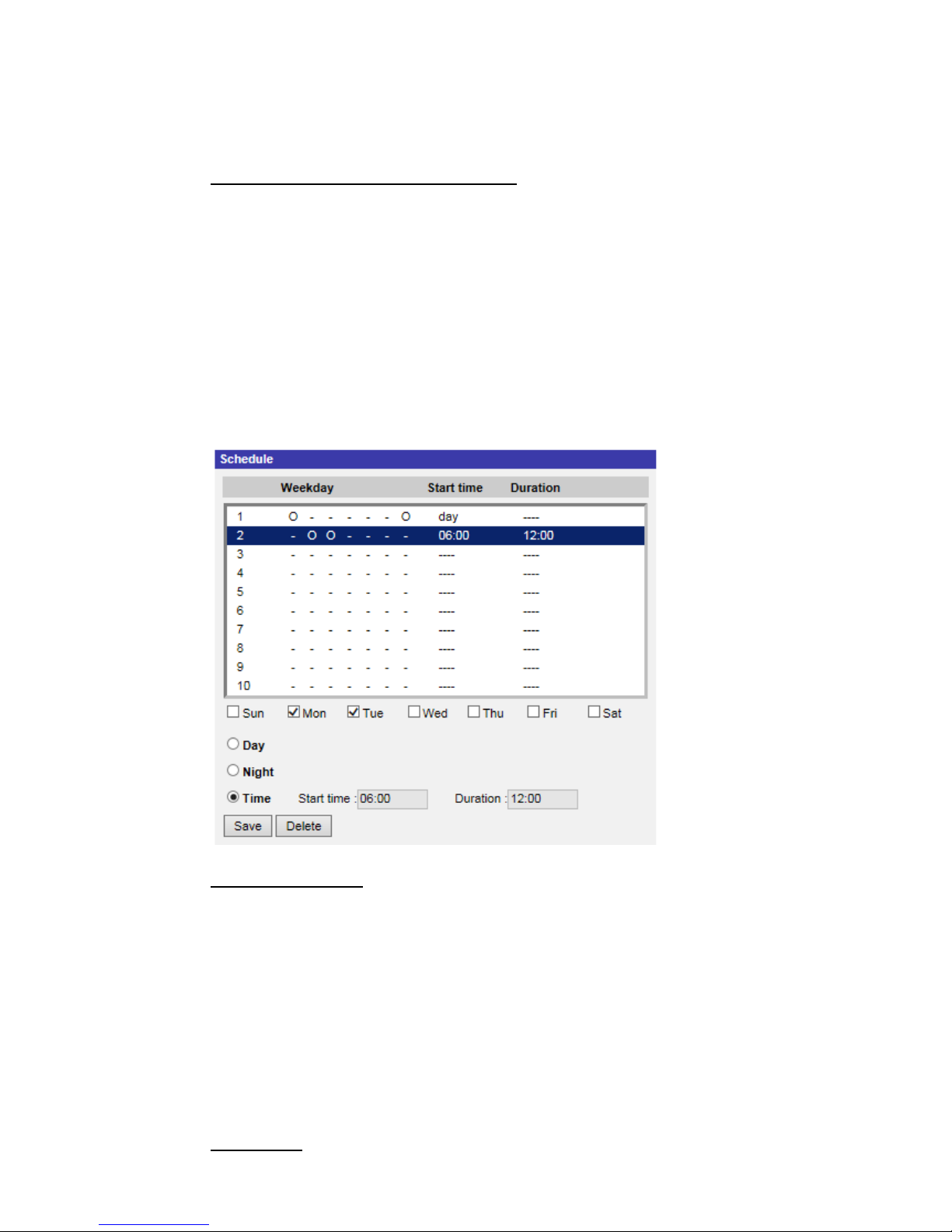
63
Select a recording schedule from the schedule list, and click <Delete> to delete
the recording schedule.
Terminating the Recording Schedule
Select <Disable> to terminate the rec or di ng func ti on.
2.2.11 Schedule
The Schedule setting can be found under this path: System> Schedule.
This function allows users to setup schedules for features including: <Alarm
Switch>, <Motion Detection> and <Network Failure Detection>. The function
supports up to 10 sets of time frames in the time frame list.
Setting Schedules
To set a schedule, select a time frame from the time frame list first. Then check
the weekday boxes b elow t o choose th e specific weekday s. At l ast, sel ect a ti me
mode, Day , Ni ght or T ime. U nder T ime mode, specify the st art time (hour: minute)
and the time duration (hour:minute) to activate the schedule triggered features.
The setting rang e for the ti me duration is from 00: 00 to 168:5 9. Click on <Delete>
to delete a chosen ti m e fra me. Click on <Save> to save the setup.
Time Mode

64
Day
The camera profile will be loaded when IR cut filter is on.
Night
The camera profile will be loaded when IR cut filter is off.
Time
This indicates the start time and the time duration for the schedule.
NOTE: Users MUST select <By schedule> under each feature setting
page to enable the schedule function.

65
2.2.12 File Location (Snapshots and Web Recording)
The File Location setting c an b e fo und un der this path: System> File Location.
Users can specify a storage location on the PC or in the hard drive for the
snapshots and the live video recordings. The default setting is: C:\. Once the
setting is confirmed, click on <Save>, and all the snapshots and the web
recordings will be saved in the designate location.
NOTE: Make sure the selected file path contains valid characters such
as letters and numbers.
NOTE: With W indows 7 or W indows 8 operating system, to implement
the Snapshot and Web Recording functions, users must run IE as
administrator. To run IE as administrator, right click on the IE browser
icon and select “Run As Administrator” to launch IE.
2.2.13 View Information
The View Information function can be found under this path: System> View
Information.
Click on the category: <View Information>, there will be a drop-down menu with
tabs including <Log File>, <User Information>, and <Parameters>.
2.2.13.1 Log File
The Log File function can be found under this path: System> View Information>
Log File.
Click on the tab t o view the sy stem log file. The cont ent of the file pr ovi des useful
information about conn ec ti ons after system boot-up.

66
2.2.13.2 User Information
The User Information function can be found under this path: System> View
Information> User Information.
The administrator can vie w the login information and privileges of each added
user (refer to section Security).
Get User Information
All users in the network will be listed in the <User information> zone as shown
below.
User: 4321
It indic ates that one user’s log in usernam e is “Us er”, and th e passwor d is “4321”.
Get User Privacy
Click on <get user pr i vacy> at the bottom o f t he p age, and the administrator can
view each user’s privileges as shown below.
User: 1:1: 0:1
1:1:0:1= I/O access: Camera control: Talk: Listen (refer to section Security)
Therefore, it de notes the us er is grant ed privil eges of I/O acces s, Camera c ontrol
and Listen.
2.2.13.3 Parameters
The Parameters function can be found under this path: System> View
Information> Parameter.
Click on this item to view the parameter settings of the en tire system, such as
Camera Settings, Mask Information and Network Information.

67
2.2.14 Factory Default
The Factory Default setting can be found under this path: System> Factory
Default.
Users can follow the instructions on this page to reset the camera to factory
default settings if needed.
Full Restore
Click on <Full Restore> to recall the fact ory d efault se tting s. The camera system
will restart in 30 seconds. The IP address will be restored to default. After the
camera system is restarted, reconnect the camera using the default IP address.
The default IP address is 192.168.0.250.
Partial Restore
Click on <Partial Restore> to recall the factory default settings (excluding
network settings). The camera system will restart in 30 seconds. Refresh the
browser page after the camera system is restarted.
NOTE: The IP address will not be restored to default.
Reboot
Click on <Reboot> and the camera system will restart without changing the
current settings. Refresh the br ow ser pag e af ter the camera system is restarted.
2.2.15 Software Version
The Software V ersion can be found under this path : System> Software V ersion.
The current software version is displayed on the software version page.

68
2.2.16 Software Upgrade
The Software Upgr ade setting can be foun d under this path: Sy stem> Software
Upgrade.
NOTE: Make sure the upgrade software file is available before carrying
out software upgrade.
The procedure of software upgrade is as below.
Step 1: Click on <Browse> and locate the upgrade file, for example,
“ulmage_userland”.
NOTE: Do not change the name of the upgrade file, or the
system will fail to find the file.
Step 2: Pick a file type from the drop-down list. In this case, select
“ulmage+userland.img”.
Step 3: Click on the <Upgrade> button. Then the syste m will prepare to start
the software upgrade. Subsequently, an upgrade status bar will be
displayed on the page to show the current upgrade process. After the
upgrade process is finished, the DCviewer will return to the <Home>
page.
Step 4: Close the video browser.
Step 5: Click on <Start> and activate the <Control Panel>. In the appeared
window, double click on <Add or Remove Programs>. A window wi th
the <Currently install programs> list will popup. In the list, select
<DCViewer> and cl ick on <Remove> to uninstall the existing DCViewer.
Step 6: Open a new web browser and re-login the camera. Users will be
prompted to download the DCViewer. Once the DCViewer is
downloaded and installed, the live video will be available.

69
2.2.17 Maintenance
The Maintenance setting c an be found under this path: Syst em> Main t enan c e.
Users can export configuration files to a specified location and retrieve data by
uploading the configuration file to the camera.
Export
Users can save the system settings by exporting a configuration file (.bin) to a
specified location for future use. Click on the <Export> button, and the popup
File Download window will come out. Click on <Save> and specify a desired
location for saving the configuration fil e.
Upload
To upload a configuration file to the camera, click on <Browse> to select the
configuration file and then click on the <Upload> button for uploading.

70
2.3 Streaming
Under the tab <Streaming>, there are categories including: <Video Format>,
<Video Compression>, <Video OCX Protocol>, <Video Frame Rate>, and
<Audio>.
In the Streaming submenu, the administrator can configure specific video
resolution, video compression mode, video protocol, audio transmission mode,
etc. Further details of these settings will be specified in the following sections.
NOTE: Only Administrator can access the <Streaming> configuration
page.

71
2.3.1 Video Format (Video Resolution and Rotate Type)
The Video Format setting can be found under this path: Streaming> Video
Format.
Video Resolution
Under Video Resolution section, the available video resolution formats include
MJPEG and H.264. Please refer to Appendix D: Video Resolution for more
combination details.
Click on <Save> to confirm the setting.
Text Overlay Settings
Users can select the items to display data, including date / time / text on the live
video pane.
Include date/time
Check the box to enable date, time, or date & time display on the Live
Video Pane and decide the string align position from the drop-down list.
Include text string
Check the box to enable text string display on the Live Video Pane and
decide the string align position from the drop-down list. The maximum
length of the text string is 15 alphanumeric characters.
Include subtitle
Check the box to enable subtitle display on the Live Video Pane. Users
can set at most 5 subtitles, and the maximum length of each subtitle is
16 alphanumeric characters.
Click on <Save> to confirm the Text Overlay setting.
Video Rotate Type
Users can change video di s play type if necessary. Selectable video rotate types
include Normal video, Flip video, Mirror video, 90 degr ee clockwise, 180 degree
rotate, and 90 degree counterclockwise. Refer to the following descriptions for
the different video rotate type.
Flip video
If <Flip video> is selected, the image will be rotated vertically.

72
Mirror video
If <Mirror video> is select, the image will be rotated horizontally.
90 degree Counter-/clockwise
Select <90 degree counter-/clockwise> to rotate the image by 90°
counter-/clockwise.
180 degree rotate
Select <180 degree rotate> to rotate the image by 180°.
Click on <Save> to confirm the setting.
GOV Settings
Users can set the G OV length to deter mi ne t he frame structure (I-frames and Pframes) in a video st r e am for saving bandwidth. Less bandwidth i s needed if the
GOV length is set to a high value. However, the shorter the GOV length, the
better the video quality is. The setting ra nge is from 1 to 255. The default value
for H.264-1 / H.264-2 / H.264-3 / H.264-4 is 60 / 60 / 30 / 30 (NTSC) or 50 / 50 /
25 / 25 (PAL). Click on <Save> to confirm the GOV setting.
H.264 Profile
Users can set each H.264 Profile to <Baseline Profile>, <Main Profile> or <High
Profile> according to its compression needs. With the same bit rate, the higher
the compression r atio, the bet ter the imag e quality is . The default s etting is <M ain
Profile>.
NOTE: Please make sure the higher compression ratio is supported by
the system before setup.
Click on <Save> to confirm the setting.

73
2.3.2 Video Compression
The Video Compr ession setting can be found under this pat h: Streaming> Video
Compression.
This setting page allows the administrator to adjust the bit rate of MJPEG and
H.264-1 / H.264-2 / H.264-3 / H.264-4. Higher value implies higher bit rate and
higher visual quality.
MJPEG Q (Quality) factor
The default setting of MJPEG Q factor is 35; the setting range is from 1 to 70.
H.264-1 / H.264-2 / H.264-3 / H.264-4 bit rate
and for H.264-4 is 1024 kbit/s. The setting range is from 64 to 20480 kbps, and
The default setti ng o f H.264-1 is 4096 kbit/s, for H.264-2 / H.264-3 is 2048 kbit/s ,
the total bit rate should not exceed 26624 kbps.
Compression Information Setting
Users can also decide whether to display compression information on the home
page.
CBR Mode Setting
The CBR (Constant Bit Rate) mode could be the preferred bit rage mode if the
bandwidth available is limited. It is important to take account of image quality
while choosing to use CBR mode.
Click on <Save> to confirm the setting.

74
2.3.3 Video OCX Protocol
The Video OCX Protocol setting can be found under this path: Streaming>
Video OCX Protocol.
In the <Video OCX protocol> setti ng page, the admi nistrator can selec t RTP over
UDP, RTP over RTSP(TCP), RTSP over HTTP or MJPEG over HTTP, for
streaming media over the network. In the case of multicast networking, users
can select the Multicast mode. Click on <Save> to confirm the setting.
Video OCX protocol setting options include:
RTP over UDP / RTP o ver RTSP(TCP) / RTSP over HTTP / MJPEG
over HTTP
Multicast Mode
Enter all required data, including <Multicast IP address>, <Multicast
H.264-1 / H.264-2 / H.264-3 / H.264-4 Video Port>, <Multicast MJPEG
Video Port>, <Multicast Audio Port> and <Multicast TTL> i nto each blank.
Click on <Save> to confirm the setting.
2.3.4 Video Frame Rate
The Video Frame Rate s etti ng c a n b e found under this p at h: Stream ing> Video
Frame Rate.
Video frame rate is for setti ng th e fra mes per sec on d ( fps) i f necessary.
MJPEG / H.264-1 / H.264-2 / H.264-3 / H.264-4 Frame Rate
The default setting of MJPEG / H.264-1 / H.264-2 / H.264-3 / H.264-4 Frame
Rate is 30 fps (NTSC) or 25 fps (PAL); the setti ng r a nge i s f rom 1 t o 3 0 (NTSC)
or 1 to 25 (PAL). The maximum range of MJPEG / H.264-1 / H.264-2 / H.264-3 /
H.264-4 Frame Rate will change according to the selected video resolution on
the <Video Format> page.
NOTE: Low frame rate will decrease video smoothness.
Click on <Save> to confirm the setting.

75
2.3.5 Audio (Audio Mode and Bit Rate Settings)
The Audio Mode setting can be found under this path: Streaming> Audio.
In this page, the administrator can adjust the sound transmission mode, the
audio gain levels and the audio bit rate. Setting for enabling sound recording to
the microSD / SDXC card is also available.
Transmission Mode
Full-duplex (Talk and Listen simultaneously)
In the Full-duplex mode, the local and remote sites can communicate
with each other sim ultaneousl y, i.e. bot h sites can s peak and lis ten to t he
other side at the same time.
Half-duplex (Talk or Listen, not at the same time)
In the Half-duplex mode, the local / remote site can only talk or listen to
the other site at a time.
Simplex (Talk only)
In the Talk only Simple x mode, the l ocal / remote si te ca n only talk to the
other site.
Simplex (Listen only)
In the Listen only Si mp l ex mode, t h e l ocal / remote site c an only listen to
the other site.
Disable
Select the item to turn off the audio transmission function.
Server Gain Setting
Set the audio input / output gain levels for the sound amplification. The audio
input gain value is adjustable from 1 to 10. The audio output gain value is
adjustable from 1 to 6. The sound will be turned off if the audio gain is set to
“Mute”.

76
Bit Rate
Selectable audio transmission bit rate include 16 kbps, 24 kbps, 32 kbps, 40
kbps, uLA W (64 kbps), ALAW (64 kbps), AAC (128 kbps), PCM (128 kbps), PCM
(256 kbps), PCM (384 kbps), and PCM (768 kbps). Higher bit rate will let higher
audio quality and require bigger bandwidth. Click on <Save> to confirm the
setting.
Recording to Storage
Select <Enable> from the drop-down menu to enable audio recording with vi deos
into the microSD / SDXC card or the NAS.
NOTE: If the chosen bit rate is not compatible with the player, there will
only be noise instead of audio during playback.
Click on <Save> to confirm the setting.

77
2.4 Camera
Under the tab <Camera>, there are submenus including: <Exposure>, <White
Balance>, <Picture Adjustment>, <IR Function>, <Noise Reduction>, <Profile>,
<Backlight>, <Digital Zoom>, <WDR Function>, <Fisheye Setting> and <TV
System>.
2.4.1 Exposure
The Exposure setting can be found under this path: Camera> Exposure.
Exposure is the amount of light received by the image sensor. It is determined
by the width of lens diaphragm opening, the shutter speed and other exposure
parameters. With these items, users can d efine how the Auto Expos ur e function
works. Users can select one of the exposure modes according to the operating
environment. Each ex posur e mo de is spec ified as follows.
Auto Mode
Max Gain
Maximum Gain can be set to reduce i mage noises. The Max Gain ran ges
from 1 to 3, or select <Off> to disable the function. The default setting is
3.
Auto Iris (Fixed Focal Lens and Motorized Lens Excluded)
In this mode, the camera will automatically adjust the iris to suit the
environment illumination. The minimum shutter speed can be set from
1/30 to 1/2 sec. (NTSC) or 1/25 to 1/3 sec. (PAL). AGC (Auto Gain

78
Control) will functio n automatical ly accor ding to the lig ht conditions of the
subject.
P-Iris Priority Mode (3x Zoom Lens and Motorized Lens Only)
P-iris priority mode is only available for 3x Zoom Lens and Motorized
Lens models only. In addition, applied with different lens, the related
setting options also vary. Refer to the following for further details.
3x Zoom Lens
Select <Auto Detect> , t he camer a w il l automat ical ly detect the bes t iri s
size for the environment. Alternatively, users can manually adjust the
iris size by selecting <Manual>. Click and to adjust the
iris size. The minimum shutter speed can be set from 1/30 sec. to 1/2
sec. (NTSC) or 1/25 sec. to 1/3 sec. (PAL).
Motorized Lens Only
Click on , and the camera will automatically detect the best iris
size for the environment. If necessary, users can select and
manually to adjust the iris size. Alternatively, click on to
reset the iris size, and the iris size will be set t o the larg est. Then, users
can manually adjust the iris size by selecting
and . The
minimum shutter speed can be set from 1/30 sec. to 1/2 sec. (NT SC)
or 1/25 sec. to 1/3 sec. (PAL).
Iris Priority Mode (3x Zoom Lens Only)
In this mode, it is the iris that has premier priority in control of the
exposure. The range o f the i ris siz e is from 0 t o 9, or s elects < Ful l open>
to fully open the iris. The minimum shutter speed can be set from 1/30
sec. to 1/2 sec. (NTSC) or 1/25 sec. to 1/3 sec. (PAL).
Auto Shutter Mode (Motorized Lens Excluded)
In this mode, the camera will automatically adjust the shutter speed and
the iris size accor ding to the l ight int ensity . It is al so effecti ve if a fix ed ir is
lens is being used. The minimum shutter speed range is configurable
from 1/500 t o 1/2 se c. (NTSC) or 1/42 5 to 1/1.5 sec. (PAL) for 3x Zoom
Lens Models, and from 1/500 to 1/2 sec. (NTSC) or 1/425 to 1/1.5 sec.
(PAL) for Fixed Focal Lens and Fisheye Lens Models.
Shutter Priority Mode (Motorized and Fixed Focal Lens Excluded)

79
In this mode, it is the shutter speed that takes the main control of the
exposure. The range is configurable from 1/500 to 1/30 sec. (NTSC) or
1/425 or 1/25 sec. (PAL).
NOTE: This mode is not available for Fisheye IP Camera.
Manual Mode
With this mode, users can select the suitable shutter speed, iris size and gain
value according to the environmental illumination. The shutter speed range is
from 1/10000 to 1 sec. (NTSC) or from 1/10000 to 1/1.5 sec. (PAL) and from
1/10000 to 1 sec. (NTSC) or from 1/10000 to 1/3 sec. (PAL) for 3x Zoom Lens
Models. The range of the iris size is from 0 to 9, or selects <Full open> to fully
open the iris. The gain value range is from 1 to 9, or select <Off> to disable the
function.
NOTE: The <Iris Size> setting is only available for models with 3x Zoom
Lens.
NOTE: The <Gain> set ting is not av ai lable for Box Camera. Note tha t for
Motorized Lens models, the iris size setting differs. To set the iris size,
click on , and the camera will auto detect the best iris size for the
environment. If necessary, users still can manually adjust the iris size by
selecting and . Alternatively, click on to reset the ir is
size. The iris size will be set to the largest. Then, users can manually
adjust the iris size by selecting and .

80
2.4.2 White Balance
The White Balance setting can be found under this path: Camera> White
Balance.
A camera needs to find reference color te mperature, which i s a way of measuring
the quality of a light source, for calculating all the other colors. The unit for
measuring this ratio is in degree Kelvin (K). Users can select one of the White
Balance Control modes according to the operating environment. The following
table shows the color temperature of some light sources for reference.
Light Sources
Color Temperature in K
Cloudy Sky
6,000 to 8,000
Noon Sun and Clear Sky
6,500
Household Lighting
2,500 to 3,000
75-watt Bulb
2,820
Candle Flame
1,200 to 1,500
Auto Mode (Auto White Balance)
The Auto White Balance mode is suitable for environments with light source
having color temperature in the range roughly from 2700K to 7800K.
ATW Mode (Auto Tracking White Balance)
With Auto Tracking White Balance function, the white balance in a scene will be
automatically adjusted while temperature color is changing. The ATW Mode is
suitable for env ironme nts wi th light source h av ing col or temperatur e i n the ra nge
roughly from 2500K to 10000K.
One Push
With One Push function, white balance is adjusted and fixed according to the
scene the camera sees at the moment. This function is best for situations with
minimal scene chang e s and c o nti nu ous li g ht ing. The functi o n i s sui t abl e f or li g ht
sources with any kind of color temperature. Follow the steps below to set the
white balance.
Point the camera to the monitoring area.
Select <One Push> in the White Balance setting menu
Click the button to adjust the color tone of the live images.
NOTE:
In this mode, the value of white balance will not change as the
scene or the light sour ce vari es. There fore, us ers might have to re-adjust
the white balance by clicking the
button again when needed.

81
Manual Mode
In this mode, users c an manually adjust t he White Balance v alue. Input a numbe r
between 0 to 127 for “Rgain / Bgain” to adjust the red / blue illuminant on the
Live Video Pane. The following describes several situations that might occur
during the White Balance manual adjustment.
The video image tur ns r eddi sh (as the left picture below) .
The higher the Rgain value, the redder the image will be. To solve the
problem, reduce the Rgain value, and the video image will turn less
reddish.
The video image turns greenish (as the left picture below).
The lower the Rgain value, the greener the image will be. To solve the
problem, Increase the Rgain value, and the video image will turn less
greenish.

82
The video image turns bluish (as the left picture below).
The higher the Bgain value, the bluer the image will be. To solve the
problem, reduce t he Bgain value, and the vi deo image will t urn less bluish .
The video image turns yellowish (as the left picture below).
The lower the Bgain value, the yellower the image will be. To solve the
problem, Increase the Bgain value, and the video image will turn less
yellowish.
The following imag e di splay s the g eneral col or shifts of the s cen e w hen di f ferent
Rgain / Bgain combinations are applied.

83
2.4.3 Picture Adjustment
The Picture Adjustment setting can be found under this path: Camera> Picture
Adjustment.
Brightness
The brightness level of the images is adjustable from -12 to +13. The default
value is 0.
Sharpness
The sharpness level of the i mages i s adjus tab le from + 0 to +15. The edg e of th e
objects is enhanced as the sharpness level increases. The default value is +4.
Contrast
The contrast level of the images is adjustable from -6 to +19. The default value
is 0.
Saturation
The saturation lev el of the imag es is adj ustabl e fro m -6 to +19. The d efault val ue
is 0.
Hue
The hue level o f the im ages i s a djust able fro m -12 to + 13. The defaul t val ue is 0.

84
2.4.4 IR Function
The IR Function setting can be found under this path: Camera> IR Function.
NOTE: This function is ONLY available for models with IR function.
Day/Night Function
This item is for users to define the action of the IR cut filter. Refer to the
descriptions of each option below to select a suitable mode.
Auto Mode
With this mode, th e camera wi ll decide th e occas ion to r emove t he IR cut
filter.
Night Mode
Use this mode when the environment light level is low. The IR cut filter
will be removed to allow the camera to deliver clear images in black and
white.
Day Mode
Select this mode to turn on the IR cut filter. The IR cut filter can filter out
the IR light an d al l ows the camera to del i v er h i g h quality images in color.
Smart Mode
With Smart mode, the camera will decide the occasion to remove the IR
cut filter. The Smart mode mechanism can judge whether the main light
source is from IR illumination. If so, the IR cut filter will be kept removed
(i.e. monochrome/night mode).
For cameras with built-in IR LED module, there are three additional IR function
modes available Light Sensor / Light On / Light Off.
Light Sensor Mode
IR LED lights will be turned on / off depending on the light sensor.
Light On Mode
In this mode, IR LED lights will always be on.
Light Off Mode
In this mode, IR LED lights will always be off.

85
NOTE:
<Light Sensor>, <Light On> and <Light Off> are not available for
Zoom AF Box IP Camera and Box Camera.
Day/Night Threshold
This item is for users to set when the camera should switch from day mode to
night mode or vice v ersa. The camera w ill sense the s urrounding brightness, an d
the threshold val ue stands for t he lev el o f the l ig ht. Once t he ca mera detec ts th e
light level reaches the set threshold, the camera will automatically switch to
Day/Night Mode. The range of the level is from 0 to 10, (darker = 0; brighter =
10).
Night Mode to Day Mode
The lower the value, the earlier the camera switches to Day mode. The
default value is 7.
Day Mode to Night Mode
The higher the val ue, the ear lier the c amera sw itches to Nig ht mode. The
default value is 3.
NOTE: Equipped with different CMOS sensors, the time the camera
switches to Day/Night mode may also vary from models to models even
if the threshold is set to the same value.
IR Light Compensation
With the IR Light Compensation function, the camera can prevent the center
object close to the camera from being too bright when IR LED lights are turned
on.
2.4.5 Noise Reduction
The Noise Reduction setting can be found under this path: Camera> Noise
Reduction.
The camera provides multiple <Noise Reduction> options for delivering
optimized image quality especially in extra low-light conditions.
3DNR
3DNR (3D Noise R educt ion) func tion deliv ers optimiz ed imag e qual ity especiall y
in extra low-light conditions.

86
Different lev els o f 3DN R are pr ov ided, inc ludi ng Low, Mid and High. Higher level
of 3DNR generates relatively enhanced noise reduction.
2DNR
2DNR (2D Noise Reduction) function delivers clear images without motion blurs
in extra low-light conditions.
Select <on> to turn on 2DNR function; otherwise, select <off> to turn off 2DNR
function.
ColorNR
In a dark or insufficient light environment and the camera is under color mode,
ColorNR (Color Noise Reduction) can eliminate color noise.
Three levels of ColorNR, including Low, Mid and High, are provided. The higher
level of ColorNR generates relatively enhanced noise reduction.

87
2.4.6 Profile
The Camera Profile setting can be found under this path: Camer a> Pro f ile.
Camera Profile allows users to setup the desired image parameters for specific
environments with different time schedules. Users can setup at most 10 sets of
camera parameter configuration under the Camera tab. To enable this function,
users must setup the schedul es in advanc e. Refer t o section Schedule for further
details of schedul e set up. Then , follow the steps b elow to setup a camera pr ofile.
Camera Profile Setup
Step 1. In the “Camera” tab, setup the camera parameters, such as White
Balance, Picture Adjustment, etc., excluding TV System.
Step 2. Click on Profile and its setting menu will be displayed. Select a
number from the Num drop-down list.
Step 3. Input a name for the profile in the Name field.
Step 4.
Click on the button below the Name field. The camera
configuration is sav ed and applied to the profi l e. N ow a camera profile
is created and saved.
Step 5. Select a profile from the Num drop-down list.
Step 6. Tick the By schedule box. Check the desired schedule(s) from the
Schedule drop-down list. Multiple schedules can be applied to one
profile.
Step 7.
Click on the button below <By schedule>.
Step 8. Follow the steps above to set the rest of the profiles.
Now, the camera will automatically switch profiles according to the schedule.
Alternatively, manually select a number fro m the Num drop-down list. Then, click
on the button, the camera will load and applied the setting of the profile.
NOTE: If users wish to set the camera parameters to factory default
setting, select <Normal> from the Num drop-down list. The camera will
start loading the default values.

88
NOTE: Users MUST set the camera parameter of the last profile as the
default setting. T hus, if ther e are ga ps among schedul es, the ca mera w ill
apply the setting of the last profile.
2.4.7 Backlight
The Backlight setting can be found under this path: Camera> Backlight.
The Backlight Compensation function prevents the center object from being too
dark in surroundings where excessive light is behind the center object. Select
<on> to turn on the function; otherwise, select <off> to turn off the function.
NOTE: For 3M and 4M models, Backlight function will be unavailable
when the TV system option is set to video format with “WDR 2 Shutter”
or “WDR 3 shutter” under <TV System>.
2.4.8 Digital Zoom
The Digital Zoom setting can be found under this path: Camera> Digital Zoom.
The digital zoom of the camera is adjustable from x2 to x10.
NOTE: This function is NOT available for Fisheye IP Camera models.

89
2.4.9 WDR Function
The WDR Function setting can be found under this path: Camera> WDR
Function.
The Wide Dynamic Range (WDR) function is for solving high contrast or
changing light issues so that enhances better video display. Different level
options for WDR includ e L ow, Mid and Hi. Higher level o f WDR represents wi der
dynamic range, so that the camera can catch a greater scale of brightness.
Gamma WDR
The Gamma Wide Dynamic Range (Gamma WDR) function is also designed to
solve contrast or changing light issues and to enhance the video display quality.
Different lev el opti ons for Gamma WDR include Low, Mid and Hi. The higher the
level, the wider t he dynamic range is. Thus, the camera c an catch a greater s cale
of brightness.
Shutter WDR
The shutter WDR function can be disabled by selecting <On>.
NOTE: <Gamma WDR> and <Shutter WDR> are only available for 3M /
4M models of the IP cameras. In addition, the TV system option must be
set to video format with “WDR 2 Shutter” or “WDR 3 shutter” under <TV
System>.

90
2.4.10 Fisheye Setting (Fisheye IP Camera Only)
The Fisheye setting can be found under this path: Camera> Fisheye Setting.
At this setting page, users can choose a dewarping method for correcting the
fisheye source images, and select the camera’s installation method to view the
dewarped images with the correct viewing modes. Please refer to the following
sub-sections Fisheye Dewarping Type and Installation for more details.
After a suitable dewarping method and the correct installation method are
selected, users can view the dewarped images from the camera’s web browser
configuration interface. Click on the Fisheye Image Adjustment buttons on the
home page and view the dewarped images in the preferred viewing mode.
Alternatively, users can view the dewar ped images through a backend device or
via backend software that has dewarping function. Please refer to its User’s
Manual for more details.
NOTE: The Fisheye I mag e Adjustment b utt ons ar e di f ferent ac cor din g to
the dewarping method and installation method selected at this setting
page. Please re fer to the tables at sub-section Fisheye Image Adjustment
under section Function Items on Home Page for the supported buttons.
Fisheye Dewarping Type
This item is for users to choose a method to dewarp the fisheye source images.
The options are < Front End C orrection> and <Back E nd Correction> . Please s ee
below for more details. After a dewarping method is selected, click <Save> to
confirm the setting.
Front End Camera Dewarping
Front End Camera Dewarping is a dewarping method that corrects
fisheye source images only by the camera. Dewarping images by the
camera can reduce network usage and image processing load of the
backend device. It also all ow s the camera to r ec ord or tak e snaps hot s o f
the dewarped images.
With this method, w hen v iewing the dewarpe d images from th e cam era’s
web browser configuration interface, video format needs to be set to the
second stream. Refer to the following instructions to view the dewarped
images.

91
Step 1. Select the camera’s installation method at <Installation> and
click <Save>. For more details, please refer to sub-section
Installation below.
Step 2. On the home page, set the <Video format> under the liv e video
window as H.264-2 or MJPEG.
Step 3. The Fisheye Image Adjustment buttons will appear on the
home page and under <Installation> at the <Fisheye Setting>
setting page.
Step 4. Users can view the dewarped images on the home page or at
the <Fisheye Set ting> setti ng page. Click on the buttons to vi ew
the dewarped images in the preferred viewing mode.
Back End Software Dewarping
Back End Software Dewarping is a dewarping method that corrects the
fisheye source images by a backend device or a backend software with
dewarping function. Dewarping by this method can correct high
resolution images and deliver clear dewarped images.
With this method, users can also view the dewarped images from the
camera’s web browser configuration interface. The video format can be
set to any available st ream. The fisheye source i mages w ill be dewar ped
by the Viewer an d displ ayed on t he home page. Howev er, users c an only
record video or take snapshots of the fisheye source images delivered
from the camera.
Installation
This item is for user s to select the c amera’s i nstallation method, so the dew arped
images can be vi ewed w ith the corr ect v iewing modes. Select a method from t he
drop-down list according to the location that the camera is installed. Choose
<Ceiling Mount> if the camera is mounted to the ceiling, or select <Wall Mount>
if the camera is mounted to the wall.
Refresh Rate
This item is for users to adjust the speed of the virtual PTZ. The refresh speed
options are 5, 10, 15, and 20. The larger the value, the faster the pan tilt
movement is.

92
NOTE: This item is o nly availabl e when < Front End Ca mera Dew arping >
is selected in <Fisheye Dewarping Type>.
Horizontal Calibration
This item is for users to calibrate images counterclockwise / clockwise.
NOTE: This i tem is only avai lable when <Back End S oftware Dewarping >
is selected in <Fisheye Dewarping Type> and <Wall Mount> is selected
in <Installation>.
Counterclockwise
Users can click on the <1> or <10> button to calibrate the image
counterclockwise one degree or ten degrees.
Clockwise
Users can click on the <1> or <10> button to calibrate the image
clockwise one degree or ten degrees.

93
2.4.11 TV System
The TV System setting can be found under this path: Camera> TV System.
Select the video format that matches the present TV system. Click on < v > to
confirm the new setting.
The following table shows the available video formats for different types of
models. The supported video formats for each model are marked by “v”.
Model
Video Format
3M / 4M Models of
IP Cameras
Other Models of
IP Camera
NTSC
60 fps
v
v
WDR 2 Shutter
v
-
WDR 3 Shutter
v
-
PAL
50 fps
v
v
WDR 2 Shutter
v
-
WDR 3 Shutter
v
-
NOTE: To enable the shutter WDR function o f the 3M / 4M mod els of th e
IP cameras, the selected video for ma t MUST i ncl ude “WDR 2 shutter” or
“WDR 3 shutter”.

94
2.5 Pan Tilt
Under the tab <Pan Tilt>, there are submenus including : <Preset>, < Sequence>
and <Pan/Tilt Control>.
NOTE: Pan Tilt function is only available for Zoom AF Box Camera and
Box Camera (DC12V / AC24V / PoE Model (RS-485)).
With RS-485 support, the camera is capable of working with a Pan Tilt Head for
pan and tilt control. Before implementing pan/tilt control, please ensure the Pan
& Tilt Head is correctly connected to the camera’s RS-485 port.
Pin Definition for IP Camera’s RS-485 Port
6. D -
7. D +
2.5.1 Preset
The Preset setting can be found under this path: Pan Tilt> Preset.
NOTE: Before setting this function, users must enable the Pan/Tilt
Control first. Please refer to section Pan/Tilt Control for more details.
There are up to 256 preset points that can be set in the Preset setup page.
Please follow the steps below to set and run preset points.
Preset Points Setup
Step 1. Move the camera to the desired position by moving the mouse cursor
onto the screen, one left click on mouse, and then dragging the red
arrow to pan/tilt. Users may adjust the zoom position as well.
Step 2. Once a Preset Point is defined, pl ease assi gn a number (between 1 and
256) and enter it into the input field.
Step 3. Click on to save the defined preset point.

95
Preset Run
Type the Preset Point number into the Preset field, click on , and the
camera will turn to the appointed point.
2.5.2 Sequence
The Sequence setting can be found under this path: Pan Tilt> Sequence.
The Sequence function supports eight Sequence Lines. Each Sequence Line
consists of 64 Preset P oi nts. Pl e ase r e f er to t he i ns tr ucti o ns below to program a
Sequence Line.
NOTE: Before setting this function, users must pre-define at least two
Preset Points.
Sequence Setting
Sequence Line
The Sequence Lines are numbered from 1 to 8. Select a Sequence Line
from the drop-down list. Then click on to enter the setup page.
Sequential Preset Points Setting
Please setup each Preset Point of the programmed Sequence Line in
order, assigning a Preset Point from the “NO.” list for the specified
number of Preset Point and entering Dwell Time (0 sec. to 255 sec.) into
the corresponding fields. Click on <Save> when finished.
Sequence Reset
To reset the sequence setting of each line, please click on the <Reset>
button on the set up page. T hen click on on the left to refres h the
page in order to enter the new settings.

96
Sequence Run
Select the specifie d Sequence Line from the drop-dow n list, click on , and
then the camera will start moving forward each scene sequentially as
programmed.
T o view the c amera executi ng a Sequenc e Line in full screen mode, please move
the cursor onto the live view pane, right-click and left-click to sele ct “fulls creen”.
Then users can view the camera navigation in full screen.
To stop running the Seq uence Line , simpl y mov e the cur sor to the li ve v iew pane
and move the camera in any direction.
2.5.3 Pan/Tilt Control
The Pan/Tilt Control setting can be found under this path: Pan Tilt> Pan/Tilt
Control.
This page is for users to activate the pan/tilt function and select the RS-485
protocol which the Pan Tilt Head uses.
Pan/Tilt Control
This item allows users to disable or enable the Pan/Tilt Control.
Click on <Save> to confirm the setting.
RS-485 Protocol Type
With the correct RS-48 5 pr otocol selected, user s will be able to remotely control
the Pan T ilt H ead fr om the w eb brow ser or th e backe nd so ftware. Ch eck th e RS485 protocol type of the Pan Tilt Head. Then select the RS-485 protocol which
the Pan Tilt Head uses from the drop-down list. The available types are DSCP /
PelcoD / PelcoP / Universal. Please refer to the following descriptions. After the
protocol type is selected, users can adjust the parameters from the drop-down
lists on the right. Click <Save> to confirm the setting.

97
DSCP / PelcoD / PelcoP:
With these protocol s, users can control the Pan Tilt Head fro m the web browser.
Users can use the mouse to pan/tilt, set preset points and set sequence lines.
To pan/tilt the Pan Tilt Head, click and drag the mouse in the live video window
at the home page. To set preset points and sequence lines, please refer to
sections Preset and Sequence. Users can also type API (Application
Programming Inter fac e ) c om mands at t he U RL bar of the web browser interface
to control the Pan Tilt Head. For API commands please refer to IP Camera API
Parameter Specificati on. Alternativ el y, Pan Tilt H ead can also b e co ntr olled fro m
the backend so ftware. Please refer to t he User’s Manual of the b ackend so ftware
for more details.
Universal:
Universal protocol covers functions that are not provided by the protocols listed
above. Users can control the Pan Tilt Head by entering the API command of the
Universal protocol at the URL bar of the web browser. For the API command,
refer to section RS-485 Universal Protocol Control in the IP Camera API
Parameter Specificati on. Alternativ el y, Pan Tilt H ead can also b e co ntr olled fro m
the backend so ftware. Please refer to t he User’s Manual of the backend software
for more details.
NOTE: To get a co py of IP Camera API Parameter Specification, please
contact the sales representatives.
2.6 Logout
Click on the tab <Logout> on the top of the page, and the login window will
popup. This enables login with another username.

98
Appendix A: Install UPnP Components
Please follow the instructions below to install UPnP components on Windows Vista /
Windows XP / Windows 7.
Step 1: In Windows, go to <Start>, click on <Control Panel>, and then double click on
<Add or Remove Programs>.
Step 2: Click on <Add/Remove Windows Components > in the <A d d or Re move Pr ogr ams>
page.
Step 3: Select <Networking Services> from the Components list in Comp onents Wizard
window of the Windows, and then click <Details>.
Step 4: Select <UPnP User Interface> in the Networking Services’ subcomponents list and
then click on <OK>.
Step 5: Click on <Next> in the Windows Components Wizard window.
Step 6: Click on <Finish> to complete installation.

99
Appendix B: IP Addresses from Decimal to Binary
Follow the example bel ow to conver t the IP addresses to bi nary numbers . Use the calculato r
on the computer for conversion. The calculator can be found under this path: Start> Al l
Programs> Accessories> Calculator. For Windows XP and Windows V i s t a , click <Vie w>
on the calculator and cl i ck <S cienti fic> . For Windows 7 and Window s 8, cli ck < View > on the
calculator and click <Programmer>. Then follow the steps in the following example to
convert the IP addresses.
The example below shows how to convert 192.168.2.81 to binary numbers.
Step 1: On the left of the calculator, select <Dec>. Then enter the first decimal number of
the IP address, “192”. Select <Bin> and the number will be converted to binary
number. Repeat th e s ame proce dure w ith th e r est o f deci mal n umber s . Remember
to select <Dec> before entering the next decimal number. Otherwise a decimal
number cannot be entered. The table below shows the binary number of each
decimal number.
Decimal Numbers
Binary Numbers
192
11000000
168
10101000
2
10
81
1010001
Step 2: Each binary number should have eight digits. If a binary number does not have
eight digits, please add 0 in front of it until it does. The binary number of each
decimal number should be as follow.
Decimal Numbers
Binary Numbers
192
11000000
168
10101000
2
00000010
81
01010001
Step 3: Therefore, the binary numbers of IP address 192.168.2.81 is
11000000.10101000.00000010.01010001.
 Loading...