

Page 1
Multiple Streams Ultra High Definition Fisheye IP Camera (Outdoor) Quick Guide
The Quick Guide is for quick installing and connecting the V9360W-1 Fisheye IP Camera (Outdoor). For more details,
please refer to the User’s Manual of the camera in the suppl ied CD.
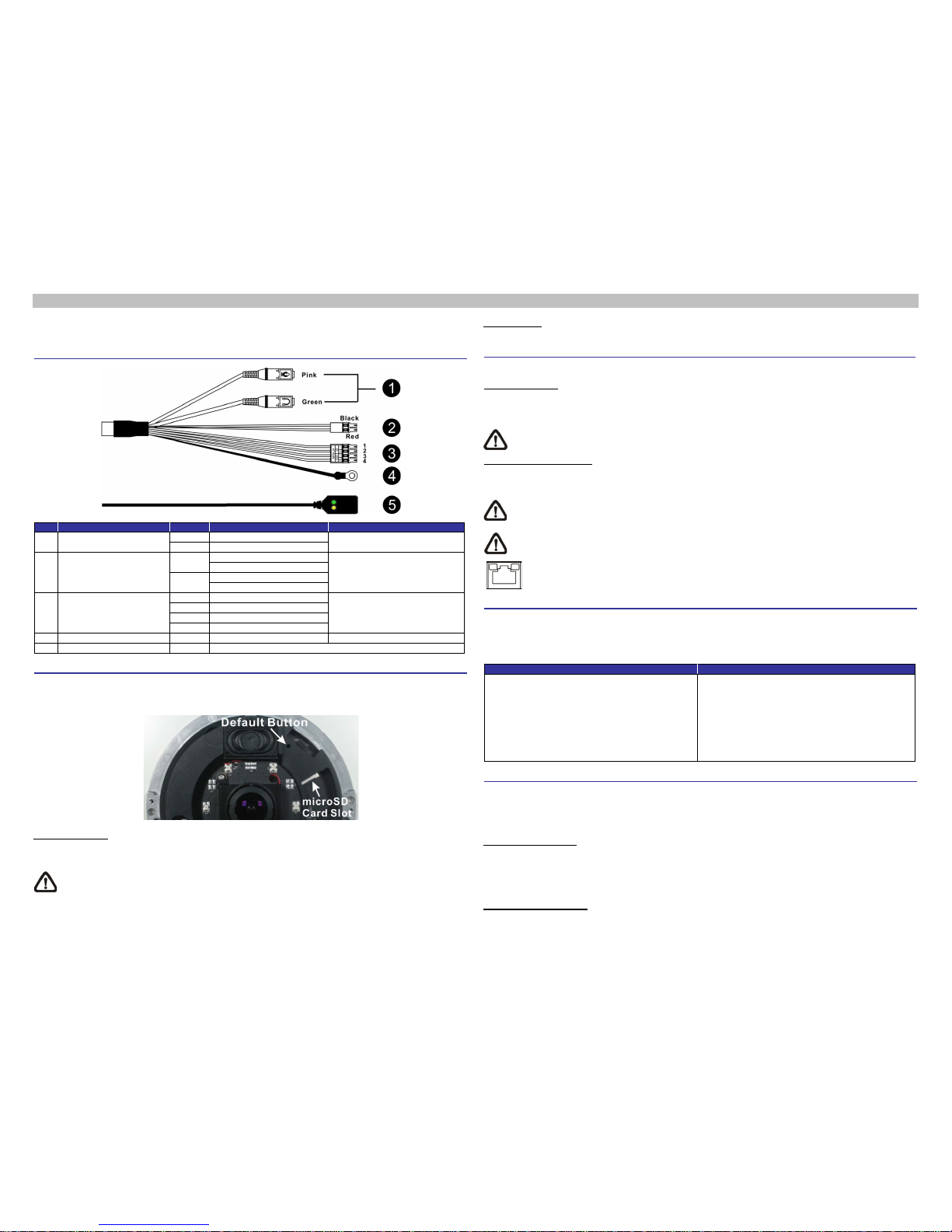
Function Cables
No.
Connector
Pin
Definition
Remarks
1 Audio I/O
Pink
Audio In
Two-way audio transmission
Green
Audio Out
2
Power (DC 12V/AC 24V)
(2-Pin Terminal Block)
Black
AC 24 V –
Power connection
DC 12V –
Red
AC 24V +
DC 12V +
3
Alarm I/O
(4-Pin Terminal Block)
1
Alarm In –
Alarm connection
2
Alarm In +
3
Alarm Out –
4
Alarm Out +
4
GND - GND
Ground connection
5
RJ-45 - For network and PoE connections
microSD Card Slot / Default Button
The camera’s microSD card slot and default button are inside the camera cov er. To use them, loosen th e t w o security
screws of the camera with the supplied security torx and detach the cover. Refer to the followings for their positions
and function.
microSD Card Slot
Insert the microSD card (not supplied) into the card slot to store videos and snapshots. Do not remove the microSD
card when the camera is powered on.
NOTE: It is not recommended to record with the microSD card for 24/7 continuously, as it may not be able to
support long term continuous data read/write. Please contact the manufacturer of the microSD card for
information regarding the reliability and the life expectancy.
Default Button
Press the button with a proper tool for at least 20 seconds to r est ore the system.
Camera Cabling
Please follow the instructions below for cable connections.
Power Connection
Please use a DC 12V/AC 24V power adaptor and plug it to the camera and the power outlet. Alternatively, users can
use an Ethernet cable and connect it to the RJ-45 connector of the camera and a Power Sourcing Equipment (PSE)
switch.
NOTE: If PoE is used, make sure PSE is in use in the network.
Ethernet Cable Connection
Connect one end of the Ethernet cable to the RJ-45 connector of the camera, and plug the other end of the cable to
the network switch or PC.
NOTE: In some cases, Ethernet crossover cable might be needed when connecting the camera dir ectly to the
PC.
NOTE: Check the status of the link indicator and activity indicator LEDs. If the LEDs are unlit, please check
the LAN connection.
Green Link Light indicates good network connectio n.
Orange Activity Light flash es for network activity indication.
Before Login to the Camera
A client program will be automatically installed to the PC when connecting to the camera. Before logging in to the
camera, please ensure downloading the ActiveX control is allowed by either changing the ActiveX controls and
plug-ins or setting Internet’s security level to default. For further details, please refer to the User’s Manual in the
supplied CD.
ActiveX Controls and Plug-ins Settings
Internet Security Level
Step 1: Start the Internet Explorer (IE).
Step 2: Select <Tools> from the
main menu of the
browser. Then click on <Internet Options>.
Step 3: Click on the <Security> tab
and select
<Internet>
, and click on <Custom level> to
change ActiveX settings.
Step 4: Set “ActiveX controls and plug-ins”
items to
<Prompt> or <Enable>.
Step 1: Start the Internet Explorer (IE).
Step 2: Select <Tools > from the
main menu of the
browser. Then click on <Internet Options>.
Step 3: Click on the <Security> tab
and select
<Internet>.
Step 4: Down the page, click <Default Level> and click
on <OK> to confirm the setting. Close the
browser window, and open a new one later for
accessing the IP camera.
Camera Login
The default IP address of the camera is found via DHCP for example:
IP Address: 192.168.0.100
Subnet Mask: 255.255.255.0
Login ID and Password
• Key in the camera’s IP address in the URL bar of the web browser window and hit on “Enter”.
• Enter the default username (ADMIN) and password (1234) in the prompt request dialog. Note that username is
case sensitive.
Install the ActiveX Control
Page 2
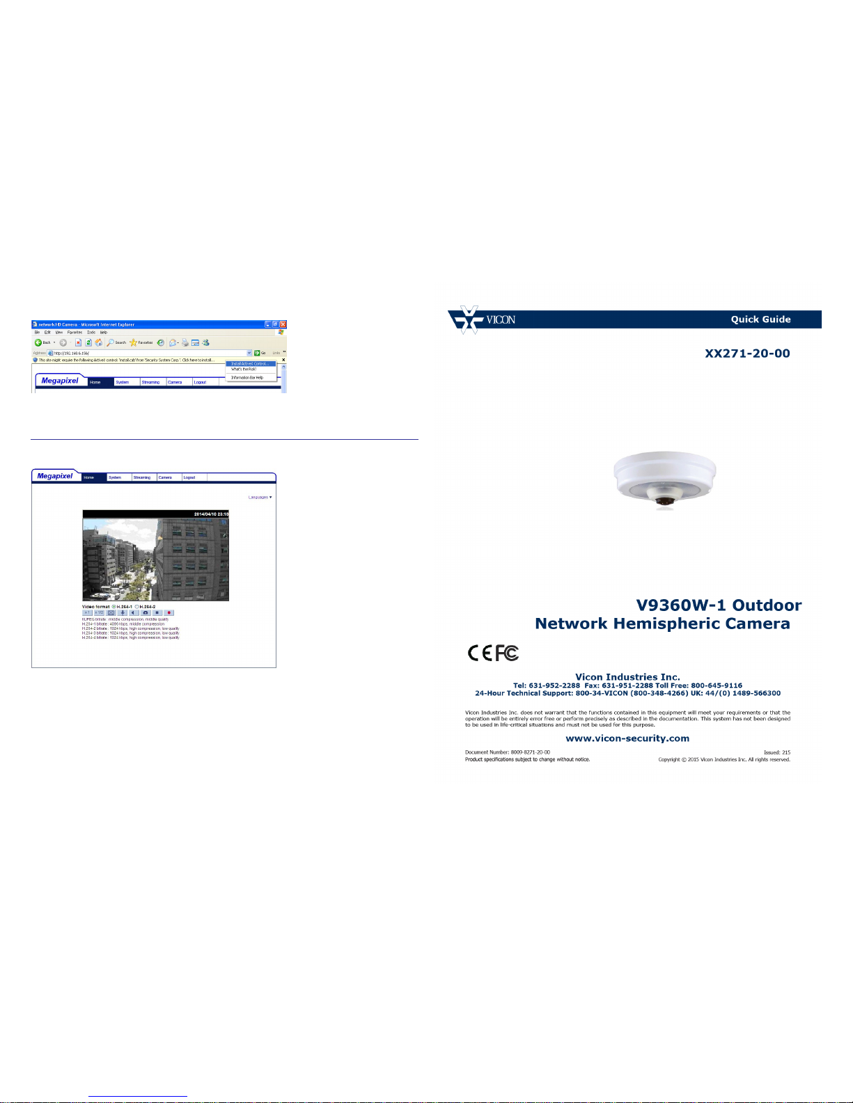
• After connecting to the camera, the request for inst alling the ActiveX control will appear just below the URL bar.
• Right click on the information bar, and then click on <Install ActiveX Control…> to permit ActiveX control
installation.
• In the pop-up security warning window, click on <Install> to start downloading DC Viewer software o n t he PC.
• Click on <Finish> after DC Viewer installation is completed.
Browser-based Viewer
The main page of the IP camera user interface is shown as the figure below. Please note that function buttons will
vary depending on the camera model.
 Loading...