

Vicon V900-358-24C, V900-2.9HC-24, V900-2.8HB-24, V900-358HB-24, V900-358HC-24 Installation & Operation Manual
...
V900 IMPACT-RESISTANT
DOME CAMERAS
X986
Vicon Industries Inc. does not warrant that the functions contained in this equipment will meet
your requirements or that the operation will be entirely error free or perform precisely as
described in the documentati on. This system has not been designed to be used in life-critical
situations and must not be used for this purpose.
Copyright © 2001 Vicon Industries Inc. All rights reserved.
Product specifications subject to change without notice.
Vicon and its logo are registered trademarks of Vicon Industries Inc.
VICON INDUSTRIES INC., 89 ARKAY DRIVE, HAUPPAUGE, NEW YORK 11788
TEL: 631-952-CCTV (2288) FAX: 631-951-CCTV (2288) TOLL FREE: 800-645-9116
24-Hour Technical Support: 800-34-VICON (800-348-4266)
UK: 44/(0) 1489-566300 INFOFAX: 800-287-1207 WEB: www.vicon-cctv.com
Vicon part number 8006-8986-03-02 Rev 1001 Section 1


Contents
Contents...............................................................................................................................i
Quick Installation................................................................................................................ii
Introduction......................................................................................................................... 1
Installation ..........................................................................................................................2
Unpacking and Inspection............................................................................................................................ 2
Inspection for Visible Damage...................................................................................................................... 2
Inspection for Concealed Damage............................................................................................................... 2
Roughneck V900 Dome Components..........................................................................................................2
Mounting the Unit .......................................................................................................................................... 3
Cable Connections ........................................................................................................................................ 4
Coaxial Video Cable.....................................................................................................................................5
Camera Power Connections ........................................................................................................................ 6
Heater Connections...................................................................................................................................... 7
Camera Synchronization...............................................................................................................................7
Camera Adjustments..................................................................................................................................... 8
Accessing the DIP Switch ............................................................................................................................ 8
Final Installation............................................................................................................................................. 9
Operation ..........................................................................................................................11
Maintenance...................................................................................................................... 11
Care and Cleaning of Lower Dome ............................................................................................................11
Shipping Instructions....................................................................................................... 12
Reference.......................................................................................................................... 13
Technical Information......................................................................................................15
X986-03-02 Rev 1001 Roughneck V900 Dome Cameras Contents •••• i

Quick Installation
For experienced installers, us e the installation diagram below, Figure 1A f or indoor versions and Figure 1B f or
outdoor versions. For complete detailed instructions on how to install the V900, read the Installation section.
Installation Diagram Exploded View – Indoor Version
ii •••• Quick Installation X986-03-02 Rev 1101 Roughneck V900 Dome Cameras
Figure 1A

Figure 1B
Installation Diagram Exploded View – Outdoor Version
X986-03-02 Rev 1001 Roughneck V900 Dome Cameras Quick Installation •••• iii


Introduction
The information in this manual covers the installation, operation, and maintenance of the Roughneck V900
Series of Impact-Resistant Dome Cameras. These units should only be installed by a qualified technician
using approved materials in acc ordance with national, state and local wiring codes. Read this manual through
completely before attempting installation.
The Roughneck V900 Series of Impact-Resistant Dom e Cameras offer s high-security cameras in a compact
domed housing. They are available for indoor and outdoor applications. Indoor versions have sand cast
construction; outdoor models are permanent mold construction. Both have a high-impact polycarbonate plastic
dome. These camera packages are designed to handle the toughest environments, including correctional
facilities, warehouses and loading dock s. The outdoor models include neoprene sealing and heaters to allow
operation in low temperature and in all weather conditions. Tamper-resistant screws make both units resistant
to vandalism.
The base of the unit screws directly to a wall or ceiling. The camera mount offers adjustment to any view
required. The camera position is adjustable horizontally and vertically (there is full 180° camera mounting
adjustment). T he V900 series has an integral camera, high-r esolution monochrom e or color, with a choice of
lenses. Both monochrome and color cameras accept 24 VAC or 24 VDC, while color cameras also feature line
lock capability. If varifocal lens models are selected, there is lens adjustment capability and autoiris
adjustment is available by a potentiometer. Refer to Table 1 for a complete listing of models.
The Roughneck V900 Dome Camera series meets FCC requirements for a Class A device. This product
complies with European Comm unity EMC Directive 89/336. The product was subjected to the testing outlined
in European Normalization Standard EN 50081-1 (Electromagnetic Compatibility - General Emissions
Standard Part 1: Residential, Comm erc ial and Light Industry), and EN 50082-1 (Electr om agnetic Com patibility
- Generic Immunity Standard Part 1: Residential, Commercial and Light Industry).
Table 1
Models, Product Codes and Descriptions
Model Product Code Description
V900-2.8HB-24 6524-04 Indoor; 1/3-in. high-resolution monochrome camera and 2.8 mm
lens; 24 VAC/VDC. EIA.
V900-358HB-24/
V900-358-24C
V900-2.9HC-24 6514-04 Indoor; 1/4-in. high-resolution color camera and 2.9 mm lens;
V900-358HC-24/
V900-358HC-24C
V900-358HCA-24/
V900-358HCA-24C
6526-04/6526-03 Indoor; 1/3-in. high-resolution monochrome camera and
3.5 - 8 mm varifocal lens; 24 VAC/VDC. EIA/CCIR.
24 VAC/VDC. NTSC.
7567-00/7567-01 Indoor; 1/3-in. high-resolution color camera and 3.5 - 8 mm
varifocal lens; 24 VAC/VDC. NTSC/PAL.
7568-00/7568-01 Outdoor; 1/3-in. high-resolution color camera and 3.5 - 8 mm
varifocal autoiris lens; 24 VAC/VDC; heater. NTSC/PAL.
X986-03-02 Rev 1001 Roughneck V900 Dome Cameras Introduction •••• 1

Installation
Unpacking and Inspection
All Vicon equipment is tested and inspected before leaving the factory. It is the carrier’s responsibility to deliver
the equipment in the same condition as it left the factory.
Inspection for Visible Damage
Immediately inspect the cartons upon deliver y. Make a note of any visible damage on all copies of the carrier’s
freight bill.
Make sure the carrier’s agent (the person making the delivery) signs the note on all copies of the bill. If the
agent does not have claim forms, contact the carrier’s office.
Inspection for Concealed Damage
As soon as pos sible after delivery, unpack the unit and inspec t it for concealed damage. Do not discar d the
carton or packing m aterials. If the unit is dam aged, c ontact the carrier immediately and request forms for filing
a damage claim. Make arrangements for a representative of the carrier to inspect the damaged equipment.
If the equipment must be returned for repair, follow the Shipping Instructions at the end of this manual.
Roughneck V900 Dome Components
The Roughneck V900 units consist of a base (which includes the camera mounting bracket with the
camera/lens assembly) and a cover with a clear dome; some models include a mask. Some units are
delivered completely assembled; others require lens installation. Refer to Figure 1.
Base/Camera Mounting Bracket
The base of the indoor unit is cons tructed of sand cast aluminum; the outdoor unit’s base is constructed of
aluminum permanent mold casting. The base is mounted directly to the wall or ceiling. Two cable access
holes are provided. A safety cord is provided to connect the c over to the base. T he cam era mounting br acket
is attached to a yoke in the base; the camera is factory-installed (s ome units require lens installation, while
other have the lens factory installed). The camera/lens position can be manually adjusted. A heater is installed
on the yoke in outdoor units.
Mask
A gray foam mask is provided with some units to fit over the camera/lens assembly.
Cover/Dome
The cover of the indoor unit is constructed of sand cast aluminum ; the outdoor unit’s cover is construc ted of
aluminum permanent mold casting. Both have a 3.5 in. (89 mm) diameter dome constructed of clear
polycarbonate plastic. The cover is s ecured to the bas e with four tam perpr oof c aptive scr ews; a special tool is
supplied to loosen the screws. A safety cord is provided to anc hor the cover/dome to the base. A heater is
factory-installed inside the cover. Refer to the Maintenanc e section of this m anual for ins tructions on the care
and handling of the dome.
2 •••• Installation X986-03-02 Rev 1101 Roughneck V900 Dome Cameras

Mounting the Unit
Select a location for the installation of the V900 c amera. Be sure the area around the selected location is clear
of obstacles (such as steel beams, headers, pipes, electrical wiring, etc.) which would interfere with the
mounting of the cam era and that the location can support the weight of the unit [the V900 unit weighs 4 lb
(1.8 kg)]. Video and power cables must be routed to the installation location.
The V900 mounts direct ly to a ceiling or wall. The base has four mounting holes, and two cable access holes
are provided. As a mounting alternative, the m ounting holes align with a standard 4 x 4 electrical box, and the
unit may be mounted to that. Refer to F igure 2. All the hardware needed to mount the base to the wall or
ceiling is provided in the accessory kit. To mount the V900, follow the steps below.
Caution: Do not attach these units to drywall surfaces and do not install mounting screws into the end
grain of wood.
1. Loosen the four captive screws securing the cover to the base with the special tool supplied in the
accessory kit. T he cover remains attached to the base by a safety cord. Allow the cover to hang. Remove
the mask from the camera/lens assembly.
2. Using the base as a template, m ark the loc ation of the four m ounting holes [0.265 in. (6.7 mm) diameter].
See Figure 2.
3. Drill a hole in the wall or ceiling and route video and power cables to the location and through one of the
cable access holes provided. A 1/2-inch conduit c onnection (custom er- supplied connector) is provided on
the side of the base; a liquid-tight connector [threaded, 0.69 in. ( 17.5 mm) diameter] is provided in the
accessory kit for base mounting. See Figures 1 and 2.
Note: If the conduit fitting on the side is us ed, the base should be mounted so the conduit connection is as
close to the bottom of the unit as possible to prevent water from entering the unit.
4. Optional Step: If it is desirable to conver t the threaded port (D IN 40430 Pg 11) for the liquid tight fitting to
a 1/2-inch NPT, an adapter is needed (Pg11 to 1/2-in. NPT). This adapter is commer c ially available or can
be ordered from Vicon, part number 8004-9317-01. Screw the adapter clockwise into the fitting and
tighten with a wrench. Vicon recomm ends the use of Tef lon tape, wrapped clockwise around the threads
of the adapter, to ensure a snug fit. Refer to Figure 3 for installation options.
5. Fasten the base to the wall or ceiling with the appropr iate hardware provided for the mounting surface, the
lag bolts and sleeve f or cement surfaces or the m achine screws for other surfaces. A nylon washer is
provided at each mounting hole for envir onmental sealing. If the c able access on the m ounting surface is
used, the connector s hould be situated in the cut out cable access hole to allow a flush installation of the
base. As a mounting alternative, align the mounting holes with a 4 x 4 electrical box and fasten the base to
the box with the machine screws.
6. If the lens was not factory installed, screw the lens onto the camera.
7. On indoor models, loosen the set screw on the yoke holding the camera mounting plate to rotate the
camera/lens assem bly to desired position. Tighten the set screw. On outdoor models, sim ply rotate the
camera/lens assembly to desired position. To adjust the tilt position of the camera/lens assembly on
indoor versions, loosen the nuts on each side of the yoke and move the cam era to desired position. On
outdoor models, loosen the nuts on the vertic al adjustment bracket to move the camera to the desired
position. Tighten the nuts. Do not move the camera/lens assembly by holding onto the lens. For
outdoor units, there is a roll adjustment: loosen the two (2) thumb screws and rotate unit to desired
position; tighten thumb screws. If a unit with a varifocal lens is being installed, the lens can be m anually
adjusted for ir is, f ocus and angle of view (telephoto/wide). On autoir is m odels, ther e is a potentiom eter f or
adjustment. When making adjustments, be sure that the lens does not hit the dome.
X986-03-02 Rev 1001 Roughneck V900 Dome Cameras Installation •••• 3

To assure a watertight seal, apply silicone sealant around the area where the base m eets the wall or
Note:
ceiling.
Figure 2
Mounting Hole Pattern
Figure 3
Installation of NPT Adapter
Cable Connections
Both power and video connections are m ade to the printed circuit board (PC board) mounted to the c amera
mounting plate. Refer to Figure 4A and 4B when perf orming these connections. Refer to the Coaxial Cable
Recommendation in the reference section.
4 •••• Installation X986-03-02 Rev 1101 Roughneck V900 Dome Cameras

Coaxial Video Cable
Some Roughneck V900 off ers two options for connecting video cables to the c amera. The first method is to
attach a customer-s upplied male BNC connector to the video cable and then connect it to the mating BNC
connector on the pendant cable on the PC board. As an alternative, there is a special video connector on the
PC board. Refer to Figure 4A and 4B.
1. Strip the video cable insulation to expose the ground. Refer to Figure 5.
2. Strip back the insulation to expose the conductor.
3. Slip the cable through the clamp to make ground contact and tighten.
4. Connect the center conductor to the screw terminal (P8) on the PC board.
Figure 4A
Camera/Lens PC Board – Indoor Ver sion
Figure 4B
Camera/Lens PC Board – Outdoor Version
X986-03-02 Rev 1001 Roughneck V900 Dome Cameras Installation •••• 5

Figure 5
Cable Preparation
Camera Power Connections
Note: Vicon systems and components, like most electronic equipment, require a clean, stable power source.
Voltage irregularities such as surges, drops, and interruptions can affect the operation of your
equipment and, in severe cases, damage certain c omponents. Vicon strongly recommends the use of
line conditioners, voltage regulators, and uninterruptible power supply (UPS ) systems.
Caution: Roughneck V900 series cameras are "electrically" non-isolated. This means that the AC power
input and the video output share a common ground connection. This common ground can cause
the electrical phenomenon of ground looping. "Ground loops" only occur on "multiple camera
installations" where a difference of ground potential exists between cameras, causing a base
frequency (50 Hz/60 Hz) distortion on the video signal. It affects the video by causing horizontal
line distortion, more commonly known as "hum bars".
To eliminate ground loops on multi-camera installations, Vicon suggests the following in an installation:
Use an electrically-isolated, multiple-channel power supply. This supply type provides a separate output for
each camera. These power supplies are available in several voltage and channel configurations.
Use a single-channel AC power supply for each camera. This power supply will provide the correct voltage
and electrical isolation for one camera.
Use a 1:1 voltage isolation transformer for each camera. This type of transformer is connected to an existing
AC power source and provides an isolated power source for the camera.
6 •••• Installation X986-03-02 Rev 1101 Roughneck V900 Dome Cameras

Power is connected through a three-position scr ew term inal connector on the PC board (P3). Ref er to T able 2
for the input power connections.
1. Locate the power cable screw terminal on the PC board.
2. Strip approximately 1 in. (25 mm) of insulation off power cables. Then strip off approximately 0.25 in.
(6 mm) of insulation off each individual wire. Attach the camera power cables to the cable connector
supplied in the accessory kit according to Table 2.
3. Press the cable connector onto the board screw terminal.
The camera is shipped prepared for 24 VAC/VDC.
Table 2
Camera Power Connections
Pin Number Function
1 24 VAC/24VDC
2 24 VAC Return
3 24 VDC Return
Heater Connections
The outdoor V900 has two (2) heaters, one inside the cover and one on the yoke in the base. Refer to Figure
1. The unit is deliver ed with the heater c onnec tions made to the two connectors (P4 and P6) on the PC board.
Refer to Figure 4. The heater in the cover is connected to the connector P6; the heater in the base is
connected to connector P4.
Camera Synchronization
When the V900 is being powered by 24 VAC, c am era synchronization is line lock ed. If ther e is m ore than one
unit in a system, the cameras have to be s ynchronized to ensure there is no disruption of video display. If the
camera will be used in a line lock video application (high-r esolution color c amer as only), the camer a interface
board is already set in line lock mode by default. The use of line-locking synchronization using a V-phase
potentiometer (pot) is typically included in video equipment requiring external video synchronization. As an
example, equipment like a video switcher unit uses the camera’s line lock to reduce “video jump” on its
monitor during c amer a switching. T he V-phas e pot allows video to power line phase adjus tment up to 180°. If
more than 180° of adjustment is required, swap the lines attached to the 24 VAC terminal block connector. For
1/3-inch color cam eras, be sure that the selector s witch is set to position “LL” shown in Figure 8 and jum per
JP1 must be in place; for the 1/4-inch color c amera, j umper JP1 mus t be in place. Note that the perf ormanc e
of the cam era’s line lock depends on the quality of the power source. If the camera experienc es roll or jitter
due to the quality of the power source, then it is best to set the camer a to internal “c rystal” mode. T his is done
by setting the selector switch to “INT.” as shown in Figure 8 and removing JP1 for 1/3-inch cameras or
removing jumper JP1 for 1/4-inch cameras.
A potentiometer on the PC board (R5) is s upplied to adjust synchronization. Refer to Figure 4. With a sm all
screwdriver (preferably plastic to avoid the risk of shorting out other internal components), turn the
potentiometer on each PC board until the video im ages on the monitor are steady so there is no rolling or
disruption of the display.
X986-03-02 Rev 1001 Roughneck V900 Dome Cameras Installation •••• 7
Camera Adjustments
The lens can be manually adjusted for iris, focus and angle of view. On the lens, focus (near to infinity) is the
front ring, the telephoto/wide adjustment is the middle ring and iris (open and close) is the end ring. On autoiris
lenses, iris adjus tment may be required if the pic ture appears dark or grainy or has poor color. There is a
potentiometer (VR1, located diagonally opposite the connector cables) on the camera board to adjust the
autoiris. Turning the potentiometer opens and closes the iris to regulate light extremes. Turning the
potentiometer clock wise opens the iris wider, allowing more light. Always adjust the potentiometer from f ull
bright (wide open iris) to an acceptable video level to provide the sharpest picture possible. Line lock and
autoiris control are DIP switch selectable on the 1/3- inch high-resolution color versions . Refer to Figure 8 for
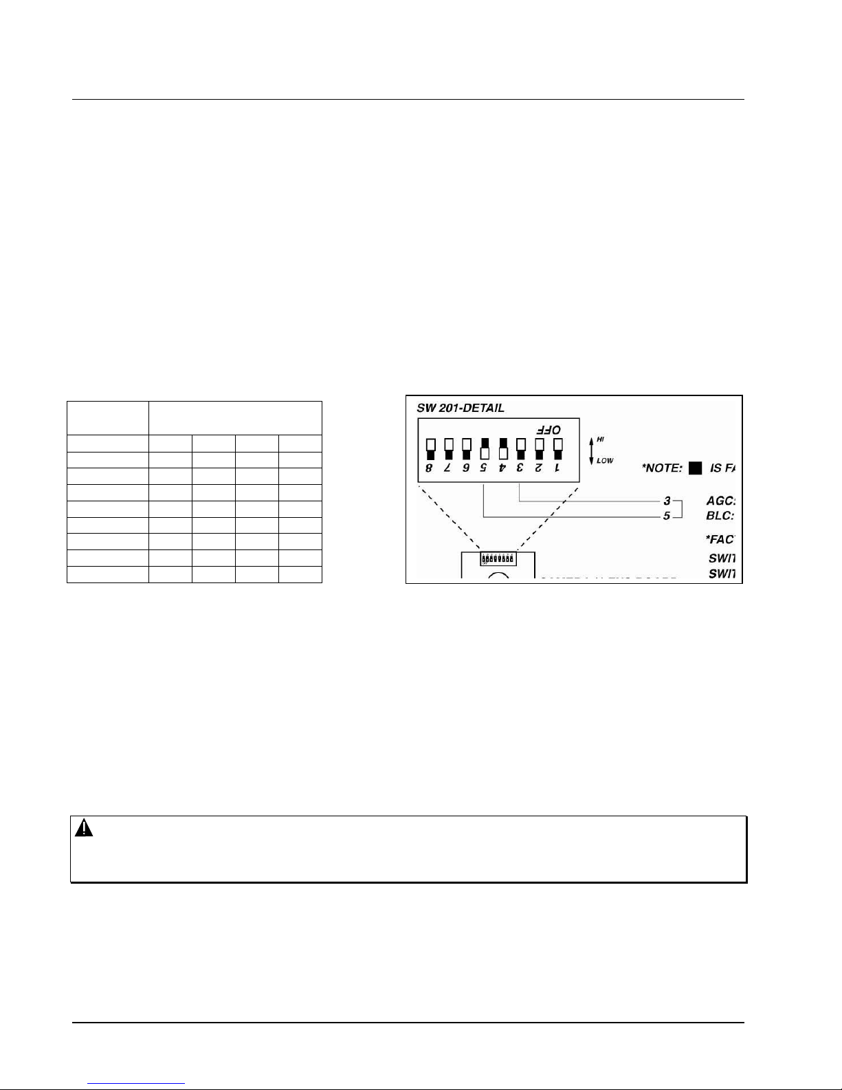
the location and setting of the switches. On the 1/4-inch high-resolution vers ion, DIP switch SW201, located
on the camera/lens board, is us ed to set camera/lens functions . Switch 7 toggles setting shutter speeds OR
setting BLC/AGC. W hen switch 7 is set OFF (Hi), switches 4, 5 and 6 control shutter s peed; when switch 7 is
set ON (Low), AGC and BLC can be set. Back light control (BLC) and automatic gain control (AGC) ON/OFF
are DIP switch selectable on this color camera (Table 3). BLC (switch 5) is factory set to OFF (Hi); AGC
(switch 3) is factory set to ON (Low). Ref er to Figure 6. In most cases, the f actory settings are preferred for
most lighting conditions.
Shutter Speed DIP Switch Settings
Shutter
Speed
1/60 (1/50) Hi Low Low Low
1/100 Hi Hi Low Low
1/250 Hi Low Hi Low
1/500 Hi Hi Hi Low
1/1000 Hi Low Low Hi
1/2000 Hi Hi Low Hi
1/4000 Hi Low Hi Hi
1/10000 Hi Hi Hi Hi
7 6 5 4
Switch No.
Figure 6
DIP Switch
Accessing the DIP Switch
Refer to Figure 7 to perform the following procedure to access the DIP switch on the 1/4-inch high-resolution
version.
1. Swing the camera/lens cradle up so that the bottom surface of the camera PCB is showing.
2. Remove the two (2) brass scr ews that secure the camera board to the lens m ount at the bottom of the
bracket.
3. Carefully remove (flip) the camera board so the DIP switch is visible.
Caution: Take care NOT to touch, move or lose the lens cover over the chip on the board.
Note the board position when removing it; it MUST be replaced exactly as it was.
4. Adjust the DIP switch settings according to Figure 6.
5. Remount the cam era board to the lens m ount in the exact orientation as it was removed using the two
screws previously removed.
8 •••• Installation X986-03-02 Rev 1101 Roughneck V900 Dome Cameras

Figure 7
Accessing the DIP Switch
Figure 8
Switch Settings
Final Installation
After all cable connections are m ade, test the camera/lens to see if any further adjustm ents are necessary.
When the camera and lens adjustments are com plete, r eplace the f oam mask over the camera/lens ass embly
(if necessary). Reattach the cover to the base by aligning the four captive sc rews with the holes in the base.
X986-03-02 Rev 1001 Roughneck V900 Dome Cameras Installation •••• 9

Any alignment of holes and screws is acc eptable. The cover can be rotated 90° by aligning the screws/holes
differently.
Caution: For moisture protection, Vicon recommends that when the cover is reattached, it compress the
gasket to a thickness of approximately 1/16 in. (1.6 mm).
10 •••• Installation X986-03-02 Rev 1101 Roughneck V900 Dome Cameras

Operation
When power is applied to the camera, the Roughneck V900 views the selected scene.
Maintenance
The Roughneck V900 Impact-Resistant Cameras require no scheduled maintenance except for the
occasional cleaning of the lower dome.
Care and Cleaning of Lower Dome
The inside surface of the smoked (gray-tinted) dome is easily scratched. Tak e the following precautions to
maintain the dome’s surface.
1. Always handle the dome by the flange and avoid touching the inside surface.
2. If dust or other contam inants ac cum ulate in the dom e’s inter ior, they should be removed with clean dry air
pressure (compressed air cans).
3. If spots, streaks or stains appear on the interior or exterior, they can be removed with a solution of
isopropyl alcohol and water using a microwave-safe (aluminum free) paper towel. Dry with clean, dry
pressurized air.
4. Sc ratches or surface blemishes on the exterior or interior may be removed with a nonabrasive wax using
a soft cleaning cloth. Either liquid or spray cleaner/wax suitable for fine furniture is acceptable.
Caution: Excessive pressure or rubbing on the dome’s surface can cause permanent scratches that may
render the dome unusable.
5. Clean all surfaces with any soft cleaning cloth and a mild cleaning agent suitable for acrylic plastic.
Caution: For warranty protection, implement this instruction exactly as stated.
X986-03-02 Rev 1001 Roughneck V900 Dome Cameras Operation •••• 11

Shipping Instructions
Use the following procedure when returning a unit to the factory:
1. Call or write Vicon for a Return Author ization (R.A.) at one of the locations lis ted below. Record the nam e
of the Vicon employee who issued the R.A.
Vicon Industries Inc.
89 Arkay Drive
Hauppauge, NY 11788
Phone: 631-952-CCTV (2288); Toll-Free: 1-800-645-9116; Fax: 631-951-CCTV (2288)
For service or returns from countries in Europe, contact:
Vicon Industries Ltd
Brunel Way
Fareham, PO15 5TX
United Kingdom
Phone: 44/(0)1489/566300; Fax: 44/(0)1489/566322
2. Attach a sheet of paper to the unit with the following information:
a. Name and address of the company returning the unit
b. Name of the Vicon employee who issued the R.A.
c. R. A. number
d. Brief description of the installation
e. Complete description of the problem and circumstances under which it occurs
f. Unit’s original date of purchase, if still under warranty
3. Pack the unit carefully. Use the original shipping carton or its equivalent for maximum protection.
4. Mark the R.A. number on the outside of the carton on the shipping label.
12 •••• Shipping Instructions X986-03-02 Rev 1101 Roughneck V900 Dome Cameras

Reference
Coaxial cables used to route video signals to and from the unit must meet the video recommendations in this section.
Caution: Careful selection of the proper cable is essential to obtain the best performance from this
equipment. Vicon assumes no responsibility for poor performance when cables other than those
recommended are installed. In all cases, coaxial cable impedance should be 75 ohms.
Materials
Use only cable with a pure copper center conductor. Do not use cable with either a copper-plated steel or an aluminum
center conductor because these do not transfer signals effectively in the frequency range used in CCTV networks. A
center conductor with low DC resistance is required for effective CCTV operation. Solid-core bare copper conductor is
best suited to video applications, except where flexing occurs. If the coaxial cable will be subjected to flexing during
normal use, select a cable with a stranded center conductor. The preferred dielectric material is cellular (foam)
polyethylene. It has better electrical characteristics than solid polyethylene, but is more vulnerable to moisture. Therefore,
use only solid polyethylene dielectric cable with a heavy exterior insulation in applications subject to moisture. The shield
must be copper braid providing 95% or better coverage.
Cable Types
The most commonly used cable types are RG-59/U and RG-11/U. Each is actually a family of cables with widely varying
electrical characteristics, some of which are not suitable for CCTV applications. Choose a cable type by referring to the
characteristics and maximum distances listed below. The maximum distance for best picture refers to the distance
between the camera and the unit The characteristics of the cables in this table should be used as a guideline when
cables other than Belden are used. Materials and construction must follow the guidelines above. Note that “BC” refers to
bare copper and “TC” refers to tinned copper.
Recommended Coaxial Cable Types
Cable
Type
Belden
Type No.
Alpha
Type No.
West Penn
Type No.
Type
Center
Conductor
Type Shield and
% Coverage
DC
Resistance
ohms per
1000 feet
(km)
RG-11/U 8213 9847 811,4811 14 Solid BC BC braid (95%) 2.6 (8.5)
RG-6/U 9248 9804C 806,4806 18 Solid BC Foil + 61% TC
braid (100%)
RG-59/U 8281 9803 815 20 Solid BC 2 TC braids (96%) 9.9 (32.5)
RG-59/U 9259 ---- 816 22 Stranded
BC
RG-59/U 9659 ---- ---- 22 Stranded
BC
BC braid (95%) 15.0 (49)
BC braid (95%) 15.0 (49)
7.5 (24.6)
Picture Quality vs Cable Length
Picture Quality
Maximum
Cable Run*
ft (m)
RG-59/U RG-6/U RG-11/U
Usable picture 1100 (350) 1500 (450) 2400 (750)
Clean picture 820 (250) 1000 (300) 1600 (500)
Best picture 400 (120) 530 (160) 820 (250)
* For longer cable runs, refer to the Product Specifications for Video Amplifiers.
X986-03-02 Rev 1001 Roughneck V900 Dome Cameras Reference •••• 13


Technical Information
ELECTRICAL
Input Voltage:
17 to 34 VDC (24 VDC nominal), nonisolated.
Power Consumption:
Current Rating:
Maximum Operating
Distance: Without Heaters
With Heaters
Heat Equivalent:
Note: These figures represent the conversion of 100% of the electrical energy to heat.
Connectors:
Video: BNC on pendant cable or special video screw terminal supplied.
Heaters: one 2-pin connector and one 3-pin connector.
Radio Frequency
Emission Rating:
European Community
(CE) Standard:
EN 50082-1 generic immunity.
Safety Standard:
Camera/Lens
14 to 25 VAC (24 VAC nominal), nonisolated.
13 W without heaters.
30 W with heaters.
0.9 A without heaters.
1.25 A with heaters.
Voltage Wire
Gauge
24 VAC 550
24 VDC 390
Voltage Wire
24 VAC 400
24 VDC 280
0.7 btu/min (0.19 kg-cal/min) without heaters.
1.7 btu/min (0.43 kg-cal/min) with heaters.
Actual percentage of heat generated will be less and will vary from product to product.
These figures are provided as an aid in determining the extent of cooling required for
an installation.
Power: 3-pin screw terminal.
FCC Class A.
EN 50081-1 generic emissions.
UL 2044.
20 18 16 14 12
859
(168)
(119)
20 18 16 14 12
(122)
(85)
(262)
609
(186)
Gauge
625
(191)
438
(134)
ft (m)
1375
(419)
975
(297)
ft (m)
1000
(305)
700
(213)
2200
(1671)
1576
(480)
1600
(488)
1120
(341)
3438
(1048)
2438
(743)
2500
(762)
1750
(533)
X986-03-02 Rev 1001 Roughneck V900 Dome Cameras Technical Information •••• 15

Specifications:
Refer to Table 3.
OPERATIONAL
Tilt and Horizontal
Adjustment:
2 axis adjustment, pan and tilt.
MECHANICAL
Application:
Indoor and outdoor models.
Mounting:
Ceiling or wall.
Dimensions:
Height: 4.8 in. (122 mm).
Total Diameter: 6.12 in. (155 mm).
Dome Diameter: 3.5. in. (89 mm).
Weight:
Approximately 4 lb (1.8 kg).
Construction:
Indoor Base/Cover: sand cast aluminum.
Outdoor Base/Cover: permanent mold cast aluminum.
Dome: polycarbonate plastic.
Finish:
Base/Cover: painted light gray.
Dome: clear.
ENVIRONMENTAL
Operating Temperature
Range:
Outdoor: 14 to 140° F (-10 to 60° C).
Operating Humidity:
Up to 95% relative, noncondensing.
Storage Temperature
Range:
-40 to 150° F (-40 to 65° C).
Storage Humidity:
Up to 90% relative, noncondensing.
Wind Load:
Outdoor: Heavy rain or snow driven by winds up to 80 mph.
16 •••• Technical Information X986-03-02 Rev 1101 Roughneck V900 Dome Cameras

Ratio
>50 dB
>50 dB
(AGC off)
>48 dB
(AGC off)
(AGC off)
>48 dB
>48 dB
(AGC off)
(AGC off)
Table 3
BLC AGC Signal-to-Noise
Synchronization Electronic Iris
Camera Specifications
On/Off,
selectable
− −
− −
On/Off,
(0.03)
selectable
1/250, 1/500,
1/60–1/100,000,
linear or 1/60, 1/100,
Automatically
Line lock (24 VAC)
(sec)
Internal 1/60 – 1/100,000
Internal 1/60 – 1/100,000
(0.03)
−
−
selectable
1/60–1/100,000
1/1000, 1/2000,
1/400,1/10,000,
selected
−
−
••
• 17
1/60–1/100,000
selectable
DIP switch
selectable
DIP switch
Lens Specifications
(TV lines) fc (lux)
Resolution Sensitivity
Color 480 0.28 (3) Internal (24 VDC)/
Mono 580 0.0028
Mono 580 0.0028
Mono
NTSC
EIA/CCIR
1/3” CCD,
2:1 interlace, EIA
Model Image Device Color/
V900-2.8HB-24 1/3” CCD,
V900-358HB-24/
2:1 interlace,
2:1 interlace,
V900-358-24C
V900-2.9HC-24 1/4” CCD,
Color 460 0.04 (0.4)* Internal/Line lock
Color 460 0.04 (0.4)* Internal/Line lock
1/3 CCD,
1/3” CCD,
NTSC/PAL
2:1 interlace,
2:1 interlace,
V900358HC-24/
V900-358HC-24C
V900-358HC-AI-24/
V900-358HC-AI-24C
NTSC/PAL
* At 40 IRE.
(mm) Horizontal Vertical
Model Focal Length Field-of-View
V900-2.8HB-24 2.8 120° -
V900-2.9HC-24 2.9 69° -
V900-358HB-24/24C 3.5-8 varifocal with manual iris 77.6° - 35.4° 57.6°- 26.6°
V900-358HC-24/24C 3.5-8 varifocal with manual iris 77.6° - 35.4° 57.6°- 26.6°
V900-358HC-AI-24/24C 3.5-8 varifocal with autoiris 77.6° - 35.4° 57.6°- 26.6°
X986-03-02 Rev 1001 Roughneck V900 Dome Cameras Technical Information •

Vicon Industries Inc.
Corporate Headquarters
89 Arkay Drive
Hauppauge, New York 11788
631-952-CCTV (2288) 800-645-9116
Fax: 631-951-CCTV (2288)
Infofax: 800-287-1207
!
Vicon Europe
Headquarters
Brunel Way
Fareham, PO15 5TX
United Kingdom
44/(0) 1489/566300
Fax: 44/(0) 1489/566322
Brussels Office
Planet II - Unit E
Leuvensesteenweg 542
B-1930 Zaventem
Belgium
322 712 8780
Fax: 322 712 8781
Far East Office
Unit 5, 17/F, Metropole Square
8 On Yiu Street, Shatin
New Territories,
Hong Kong
(852) 2145-7118
Fax: (852) 2145-7117
Internet Address: www.vicon-cctv.com
 Loading...