


V700W Series
COLOR DOME CAMERAS
About this manual
INSTRUCTION MANUAL XX178-11
Before installing and using the camera, please read this manual carefully.
Be sure to keep it handy for later reference.
This installation should be made by a qualified service person and should conform
to the National Electric Code, ANSI/NFPA 70 and all local codes.
Installers should use appropriate hardware mounting materials.

This equipment generates and uses radio frequency energy and if not installed
and used properly, that is, in strict accordance with the manufacturer’s instruction,
may cause interference to radio and television reception. It has been type tested
and found to comply with the limits for a Class A computing device in accordance
with the specification in subpart B of part 15 of the FCC rules, which are designed
to provide reasonable protection against such interference in a commercial
installation. However, there is no guarantee that interference will not occur in a
particular installation. If this equipment does cause interference to radio and
television reception, which can be determined by turning equipment off and on, the
user is encouraged to try and correct the interference by one or more of the
following measures:
FCC Notice
Note: Complies with Federal Communications Commission Rules &
RegulationsPart 15, Subpart B for a Class A digital device.
WARNING
• Reorient the receiving antenna.
• Relocate the equipment with respect to the receiver.
• Relocate the equipment away from the receiver.
• Plug the equipment into a different electrical outlet so that the
equipment and receiver are on different branch circuits.
If necessary, the user should consult the dealer or an experienced radio/television
technician for additional suggestions.

Warning: Power must be removed from this unit before removing circuit
modules or cables.
Caution: This unit contains circuit cards with integrated circuit devices
that can be damaged by static discharge. Take all necessary
precautions to prevent static discharge.
The user may find the following booklet prepared by the Federal Communications
Commission helpful:
“Interference Handbook, Bulletin CIB-2”
This booklet is available from the U.S. Government Printing Office, Superintendent of
Documents, Mailstop SSOP, Washington, D.C. 20402-9328, ISBN 0-16-045542-1.

Surface-Mount configuration In-Ceiling configuration
Dimensions : inch (mm)

PRECAUTIONS
■ Do not open or modify
Do not open the case except during maintenance and installation, as it may be
dangerous and cause damages.
■ Do not put objects inside the unit
Make sure that no metal objects or flammable substances
get inside the camera. This could cause fire, short-circuits or damages.
■ Be careful when handling the unit
To prevent damage, do not drop the camera or subject it to strong shock or
vibration.
■ Install away from electric or magnetic fields
■ Protect from humidity and dust
■ Protect from high temperature
Be careful when installing close to the ceiling , in a kitchen or boiler room,
as the temperature may rise to high levels.
■ Cleaning
Dirt can be removed from the case only by wiping it with a soft cloth moistened
with a soft detergent solution.
■ Mounting Surface
The mounting surface material must be strong enough to support the camera.

TROUBLESHOOTING
Before sending the camera out for repair, check the items below.
If the problem persists after checking these items, contact your service center.
■ If no image appears
▪ Is the coaxial cable attached securely?
▪ Are the power and voltage normal?
▪ Has the iris of the lens inside the camera been adjusted correctly
(with the level volume) ?
▪ Is there adequate illumination?
■ If the image is unclear
▪ Is the lens in focus?
▪ Is the lens dirty?
▪ Dirt or fingerprints on the lens can adversely affect the images.
Gently wipe any dirt or fingerprints off the lens with a soft cloth or
lens cleaning paper and cleaning fluid (commercially available).
▪ Is the monitor adjusted correctly?

LENS ADJUSTMENT
1. Adjust the panning (360˚) and tilt (90˚) position.
2. Set the zoom position by using Zoom Lever Screw.
3. Set the focus by using Focus Lever Screw.
4. Loosen set screws (using small M1.0 Hex L-wrench provided) to adjust roll
(turns camera position top/bottom).
PAN ROLL
SET
SCREW (2X)
TILT
90˚
ZOOM
FOCUS
SPECIFICATION - V700W-N
General Spec NTSC PAL
CCD Type 1/3" 410K Pixels Color 1/3" 470K Pixels Color
Total number of pixels 811(H) X 508 (V) 795(H) X 596(V)
Min illumination
Video Output
Resolution
S/N Ratio
Shutter speed 1/60~1/100,000sec 1/50~1/100,000sec
Sync System
White Balance
OSD Control
DNR OFF, LOW, MIDDLE, HIGHT
SENSE_UP OFF/AUTO (X2 ~ X256)
AWB
MIRROR OFF/MIRROR/V_FLIP/ROTATE
PRIVACY 6 ZONE / SIZE
Power Input
Video Output
Voltage
Power Consumption
Operation temp
In storage temp
Operation humidity
Internal / External
Connector
2 WIRE
BNC Cable
Under 90% (Non-condensing)
Mechanical Spec
14 ~ 131° F (-10 ~ 55° C)
-4 ~ 158° F (-20 ~ 70° C)
DC 12V (11V ~ 16V) AC 24V (20V ~ 28V)
DC 12V : Max 1.8 [W] AC 24V : Max 2.4 [W]
0.013 fc (0.14 Lux ) @ F1.2, 30IRE (at COLOR)
1.0Vp-p/75 ohm Composite
560 TV Lines
50dB (AGC off)
Electric Spec
Auto
ATW/ AWC/ MANUAL/ PUSH LOCK
0.003fc (0.03 Lux ) @F1.2, 30IRE (at TDN(B/W))

SPECIFICATION - V700W-I
General Spec NTSC PAL
CCD Type 1/3" 410K Pixels Color 1/3" 470K Pixels Color
Total number of pixels 811(H) X 508 (V) 795(H) X 596(V)
Min illumination
Video Output
Resolution
S/N Ratio
Shutter speed 1/60~1/100,000sec 1/50~1/100,000sec
Sync System
White Balance
OSD Control
DNR OFF, LOW, MIDDLE, HIGHT
SENSE_UP OFF/AUTO (X2 ~ X256)
AWB
MIRROR OFF/MIRROR/V_FLIP/ROTATE
PRIVACY 6 ZONE / SIZE
Power Input
Video Output
Voltage
Power Consumption
Operation temp
In storage temp
Operation humidity
BNC Cable
Electric Spec
14 ~ 131° F (-10 ~ 55° C)
-4 ~ 158° F (-20 ~ 70° C)
Under 90% (Non-condensing)
DC 12V (10V ~ 16V) AC 24V (20V ~ 28V)
LED ON = DC : Max 4.6 [W] AC : Max 4.9 [W]
Mechanical Spec
1.0Vp-p/75 ohm Composite
560 TV Lines
50dB (AGC off)
Internal / External
Auto
ATW/ AWC/ MANUAL/ PUSH LOCK
Connector
2 WIRE
0.013 fc (0.14 Lux ) @ F1.2, 30IRE (at COLOR)
0.003fc (0.03 Lux ) @F1.2, 30IRE (at IR version))

SPECIFICATION - V700W-D
General Spec NTSC PAL
CCD Type
Total number of pixels
Min illumination
Video Output
Resolution
S/N Ratio
Shutter speed 1/60~1/100,000sec 1/50~1/100,000sec
Sync System
White Balance
OSD Control
Dynaminc Range 120dB(max), 95dB(typical)
AWB
FLICKERLESS ON/OFF
Power Input
Video Output
Voltage
Power Consumption
Operation temp
In storage temp
Operation humidity
1/3" WDR CMOS sensor
742(H) X 552 (V)
Connector
2 WIRE
48dB (AGC off)
Internal / External
Auto
ATW/ AWB/ MANUAL
0.06 fc (0.6 Lux )(DSS on) @F1.2, 30IRE (at COLOR)
0.008 fc (0.08 Lux )(DSS on) @F1.2, 30IRE (at TDN(B/W))
DC 12V (10V ~ 16V) AC 24V (20V ~ 28V)
DC : Max 2.3 [W] AC : Max 3.1 [W]
1.0Vp-p/75 ohm Composite
480 TV Lines
BNC Cable
Electric Spec
Mechanical Spec
14 ~ 131° F (-10 ~ 55° C)
-4 ~ 158° F (-20 ~ 70° C)
Under 90% (Non-condensing)
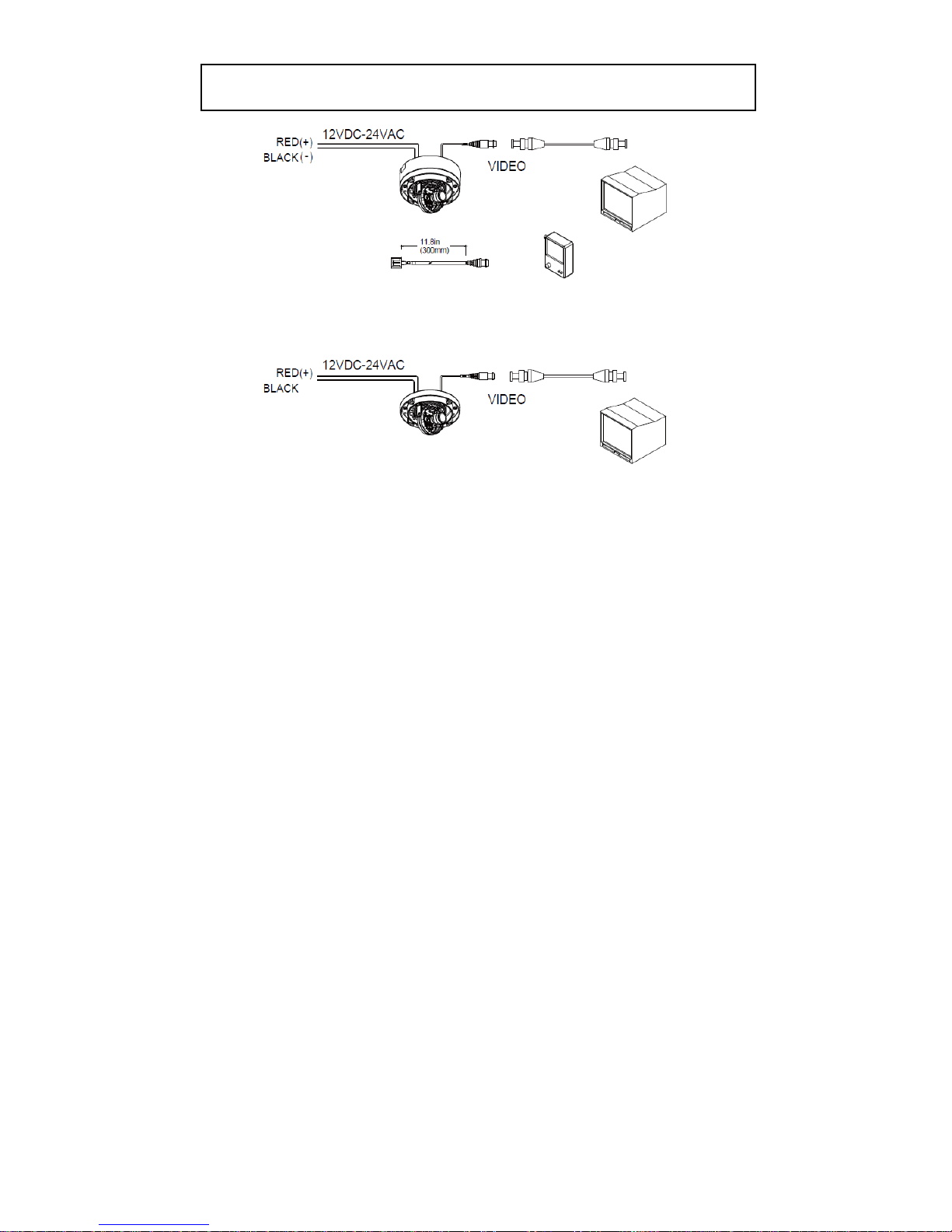
CONNECTIONS
CAUTION
The use of a UL Listed Class 2 power supply is required to ensure compliance with
electrical safety standards.
Check for polarity when using a 12 VDC power supply.
Cable for connection to portable monitor, provided.
When using a portable monitor, terminate at 75 ohms (at last device).

Surface-Mount Base
In-Ceiling Base

■ CAMERA SETTINGS FOR V700W-N AND V700W-I
CAMERA SETTINGS
CON1
SW
CON2
FUNCTION OF CONTROL BOARD
[1]. SW
Functional control of O.S.D(On Screen Display)
[2]. CON1
Second Video output connector
[3]. CON2
RS-485 connector

■ CAMERA SETTINGS FOR V700W-D
CAMERA SETTINGS
CON1
SW
CON2
FUNCTION OF CONTROL BOARD
[1]. SW
Functional control of O.S.D(On Screen Display)
[2]. CON1
Second Video output connector
[3]. CON2
RS-232 connector(1:Rx, 2:Tx, 3:GDN)
UP
①

■ CAMERA SETTINGS FOR V700W-D
(JST : BM06B-SRSS-TB(LF)(SN))
(JST : BM14B-SRSS-TB(LF)(SN))
(MOLEX : 53047-0410)
NTSC/PAL
1 2
ON NTSC X
OFF PAL X

■ OSD MENU (V700W-N, V700W-I)
LENS MASK 1
E. SHUTTER MASK 2
BLC MASK 3
MAX_DR MASK 4
AGC MASK 5
SENSE_UP MASK 6
WB MODE SYNC MODE
R-Y GAIN V_PHASE
B-Y GAIN
D&N MODE CAMERA ID
C-SUP TITLE
A-SUP DPC
MONITOR
LANGUAGE
BAUDRATE
OMNI LENS
MIRROR EXIT
SHARPNESS SAVE & EXIT
GAMMA FACTORY SET
FREEZE
NEGA
3D_DNR
D_ZOOM
SLC
HME
DIS
MOTION
SET WINDOW
ALL SET
ALL CLEAR
SENSITI
SHOW INDI
DELAY OUT
9. EXIT
5. MOTION
6. PRIVACY
2. COLOR
7. SYNC
3. DAY&NIGHT
8. SETUP
4. FUNCTION
1. EXPOSURE

■ OSD MENU (V700W-D)
MAIN MENU
DIGITAL OUT : ON or OFF
DIGITAL VIDEO
OUTPUT(Option)
ADVANCED
MENU
SETUP ID
DISPLAY ID : ON or OFF
656 OSD : ON or OFF
FRAME : FREEZE or OFF or 2x or SET..
AE PREFs
HIGHLIGHTS or SHADOWS
VIDEO OUTPUT
EXIT
EXIT NO CHANGES
SAVE NEW AND EXIT
RESTORE FACTORY SETTINGS
VERSION INFORMATION
RS485 SETUP
CAMERA # : 1< # < 255
PROTOCOL : PELCO-D
BAUD BATE : 2400,4800,9600,19200
ON
C or C-Y/C
HIGH
RESOLUTION
NORMAL
CAMERA ID : 12 CHARACTER
ID POSITION
SYNC
INTERNAL
LINE LOCK
FLICKERLESS
OFF
DAY / NIGHT
ON
COLOR -> BW LEVEL (Range 20 to 35)
B/W -> COLOR LEVEL (Range 0 to 10)
COLOR
B/W
CDS(external)
LOW LIGHT
SLOW SHUTTER
LIMIT: LEVEL (Range 0 to 60)
Max.Field : x2, x4, x8, x16, x32
B&W SS
GAIN
WB CONTROL
ATW
AWB : PUSH&LOCK
MANUAL : LEVEL (Range 2,500K to 9,500K))
AGC
OFF
ON
AGC BIAS : LEVEL (Range +18 to -18)
AGC LIMIT: LEVEL (Range 0 to 40)
LENS
MANUAL
DC : LEVEL (Range +20 to -42)
WDR
WDR BIAS : LEVEL (Range +20 to -20)
WDR LIMIT: LEVEL (Range 0 to +36)

INSTALLATION

The V700W series can be either mounted to a surface (like a ceiling or
wall) or installed into the ceiling, with or without an electrical box.
1 Use the large (Torx T20) L-Wrench to loosen the 4 screws (B) securing
the dome assembly.
2 For surface-mount installations, align the mounting base (D) with the
mounting surface; mark the mounting screw holes and then drill the four
holes. For in-ceiling installations not mounting to a 4x4 electrical box,
mark the holes in the camera assembly (C) and then drill the holes. For
in-ceiling installations, (D) is not used.
3 For in-ceiling installations, cut a hole (diameter: 2.9 in./73 mm) in the
ceiling for routing the cables.
4 Route the power cable(s) and video cable(s) to the installation location.
5 Align the four mounting holes in (D) with the holes in the ceiling.
Using the four screws and anchors provided (G), if appropriate for
mounting surface, fasten the mounting base to the wall/ceiling. Using the
other four screws provided, secure the camera assembly (C) to the
mounting base. For in-ceiling installations, align the holes in (C) with
the holes drilled in the ceiling and secure the camera assembly with the
hardware provided, if appropriate. If installing to an electrical box, secure
(C) with the screws provided.
6 Pass the power cable (E) and video cable (F) from the camera unit
through the cable hole in the ceiling. For surface-mounted units, cabling
is routed through the knockout hole in the side of the unit.
7 Carry out the settings and adjustments for the camera previously
described.
8 Secure the dome assembly (A) by tightening the screws (B).

Vicon Industries Inc.
Corporate Headquarters
89 Arkay Drive
Hauppauge, New York 11788
USA
631-952-CCTV (2288) 800-645-9116
Fax: 631-951-CCTV (2288)
European Headquarters
Brunel Way
Fareham, PO15 5TX
United Kingdom
+44(0) 1489 566300
Fax: +44(0) 1489 566322
Vicon Germany
Kornstieg 3
D-24537 Neumuenster
Phone: +49 (0) 4321 8790
Fax: +49 (0) 4321 879 97
Internet Address: www.vicon-cctv.com
Vicon Part Number 8009-8178-11-00 Rev 310
Far East Office
Unit 5, 17/F, Metropole Square
2 On Yiu Street, Shatin
New Territories,
Hong Kong
(852) 2145-7118
Fax: (852) 2145-7117
© Copyright 2010, Vicon Industries Inc.
Product specifications subject to change without notice.
 Loading...