


www.vicon-security.com
Installation and Operation Guide
XX259-00-01
V662-D-1 High-Resolution
Analog WDR Camera
Vicon Industries Inc. does not warrant that the functions contained in this equipment will meet your requirements or that the
operation will be entirely error free or perform precisely as described in the documentation. This system has not been designed
to be used in life-critical situations and must not be used for this purpose.
Vicon Industries Inc., 89 Arkay Drive, Hauppauge, New York 11788
Tel: 631-952-2288 Fax: 631-951-2288 Toll Free: 800-645-9116
24-Hour Technical Support: 800-34-VICON (800-348-4266) UK: 44/(0) 1489-566300
Document Number: 8009-8259-00-01
Issued: 513
Copyright © 2013 Vicon Industries Inc. All rights reserved.


LIMITATION OF LIABILITY
- ii -
THE INFORMATION IN THIS PUBLICATION IS BELIEVED TO BE ACCURATE IN ALL
RESPECTS; HOWEVER, WE CANNOT ASSUME RESPONSIBILITY FOR ANY
CONSEQUENCES RESULTING FROM THE USE THEREOF. THE INFORMATION
CONTAINED HEREIN IS SUBJECT TO CHANGE WITHOUT NOTICE. REVISIONS
OR NEW EDITIONS TO THIS PUBLICATION MAY BE ISSUED TO INCORPORATE
SUCH CHANGES

WARNING
TO REDUCE THE RISK OF FIRE OR ELECTRIC SHOCK, DO NOT
EXPOSE THIS PRODUCT TO RAIN OR MOISTURE. DO NOT INSERT
ANY METALLIC OBJECTS THROUGH THE VENTILATION GRILLS
OR OTHER OPENINGS ON THE EQUIPMEMT.
CAUTION
EXPLANATION OF GRAPHICAL SYMBOLS
The lightning flash with arrowhead symbol, within an
equilateral triangle, is intended to alert the user to
the presence of uninsulated “dangerous voltage”
within the product’s enclosure that may be of
sufficient magnitude to constitute a risk of electric
shock to persons.
The exclamation point within an equilateral is
intended to alert the user to the presence of
important operating and maintenance (servicing)
instructions in the literature accompanying the
appliance.
- iii -

FCC COMPIANCE STATEMENT
CE COMPLIANCE STATEMENT
- iv -
FCC INFORMATION: This equipment has been tested and found
to comply with the limits for a Class A digital device, pursuant to Part
15 of the FCC Rules. These limits are designed to provide
reasonable protection against harmful interference when the
equipment is operated in a commercial environment. This equipment
generates, uses, and can radiate radio frequency energy and, if not
installed and used in accordance with the instruction manual, may
cause harmful interference to radio communications. Operation of
this equipment in a residential area is likely to cause harmful
interference in which case the user will be required to correct the
interference at his own expense
.
CAUTION: Changes or modifications not expressly approved by the
party responsible for compliance could void the user’s authority to
operate the equipment.
This Class A digital apparatus complies with Canadian ICES-003.
Cet appareil numérique de la classe A est conforme à la norme NMB-
003 du Canada.
WARNING
This is a Class A product. In a domestic environment this product
may cause radio interference in which case the user may be required
to take adequate measures.

IMPORTANT SAFETY INSTRUCTIONS
1. Read these instructions.
2. Keep these instructions.
3. Heed all warnings.
4. Follow all instructions.
5. Do not use this apparatus near water.
6. Clean only with dry cloth.
7. Do not block any ventilation openings. Install in accordance with the
manufacturer’s instructions.
8. Do not install near any heat sources such as radiators, heat registers,
stoves, or other apparatus (including amplifiers) that produce heat.
9. Do not defeat the safety purpose of the polarized or grounding-type
plug. A polarized plug has two blades with one wider than the other. A
grounding type plug has two blades and a third grounding prong. The
wide blade or the third prong is provided for your safety. If the provided
plug does not fit into your outlet, consult an electrician for replacement
of the obsolete outlet.
10. Protect the power cord from being walked on or pinched particularly at
plugs, convenience receptacles, and the point where they exit from th
e apparatus.
11. Only use attachments/accessories specified by the manufacturer.
12. Use only with the cart, stand, tripod, bracket, or
table specified by the manufacturer, or sold with
the apparatus. When a cart is used, use caution
when moving the cart/apparatus combination to
avoid injury from tip-over.
13.
Unplug this apparatus during lightning storms or
when unused for long periods of time.
14. Refer all servicing to qualified service personnel.
Servicing is required when the apparatus has
been damaged in any way, such as power-supply cord or plug is
damaged, liquid has been moisture, does not operate normally, or has
been dropped.
15. CAUTION – THESE SERVICING INSTRUCTIONS ARE FOR USE
BY QUALIFIED SERVICE PERSONNEL ONLY. TO REDUCE THE
RISK OF ELECTRIC SHOCK DO NOT PERFORM ANY SERVICING
OTHER THAN THAT CONTAINED IN THE OPERATING INSTRUCTIONS UNLESS YOU QRE QUALIFIED TO DO SO.
- v -
16. Us
e satisfy clause 2.5 of IEC60950-1/UL60950-1 or Certified/
Listed Class 2 power source only.

- vi -
PRECAUTIONS
Before installation, carefully read the manual to ensure correct operation and setup,
heeding all warnings and instructions.
Do not block any ventilation openings. Install in accordance with the manufacturer's
instructions.
Ensure manual is kept in good condition for future use.
Do not install the device near any heat sources such as radiators, heat registers, stoves,
or other equipment (including amplifiers) that produce heat.
Only use attachments/accessories specified by the manufacturer.
Should any liquid get into the housing, immediately disconnect the device from the
power supply and have it checked by authorized personnel before reusing.
Do not install the device in a place of high humidity or where exposed to gas or oil.
Installation and servicing by authorized personnel only, adhering to local safety
regulations.
Unless you are an authorized technician, never try to dismantle the device. To avoid
electric shock, never remove the screws or covers.
If a camera, do not expose the device to radioactivity. It will cause serious damage to
the CCD.
Use Certified/Listed Class 2 power source only.
Cleaning
Clean the device with a slightly damp soft cloth. Use a mild household detergent. Never
use strong solvents such as thinner or benzene as they might damage the finish of the
unit.

TABLE OF CONTENTS
CONTENTS OF PACKAGE ------------------------------------------------------------------------- 1
INTRODUCTION --------------------------------------------------------------------------------------- 2
CAMERA OVERVIEW -------------------------------------------------------------------------------- 3
CAMERA ADJUSTMENT ---------------------------------------------------------------------------- 4
CONTROL AND CONNECTIONS / DAY&NIGHT I/O TERMINALS----------------------- 14
LENS ----------------------------------------------------------------------------------------------------- 15
SPECIFICATIONS ------------------------------------------------------------------------------------- 16
CONTENTS OF PACKAGE
Installation of the camera must be performed by qualified service personnel in
accordance with all local and national electrical and mechanical codes.
Carefully remove the color camera and its accessories from the carton and verify that
they were not damaged in shipment.
The contents of the package include:
1. Color CCD camera
2. Mini-DIN connector (for video-or DC-type auto-iris lens)
3. CS adapter ring for C mounting "C" lenses
4. This manual
- 1 -

INTRODUCTION
The V662-D-1 camera provides high-quality images using Sony 1/3” CCD and digital
signal processing LSIs.
Features:
1/3" Super-HAD CCD
Super High-Resolution (700 TVL)
Wide Dynamic Range (~x512)
Day & Night (Auto, Manual, External, Filter Delay, Change Level Adjust)
0.1 Lux (Color), 0.01 Lux (BW), 0.0001 Lux (Sens-Up B/W) @ F/1.2, 50IRE
Auto Electronic Shutter [1/60 (50) ~ 1/100,000] and Manual Electronic Shutter
Modes [1/60 (50) ~ 1/10,000]
Sens-Up (~x256)
2D-NR, 3D-NR
UDF Function(Ultra Deep Field)
Multi Camera Configuration Set (4-Sets/Night Profile, External Day/Night
Profile)
PVA/PVA+ (Personal Video Analytics)
Many Configurable Parameters
Various Detection Methods (Motion, Loitering Object, Abandon, Scene
Change, Unfocus, Windy Area)
Various Zone Event Detection Methods and Event Area Combinations
8 Objects Trace, 4 Objects Display
Concurrent Processing with All Detections and All Objects
Two Counting Blocks
Event String Sending (Editable String)
Digital Tracking (Using D-PTZ)
Various Detection Areas (max. 10 areas; Line, Rectangle, 4-Point
polygonal)
Backlight Compensation (EHLC, Auto, Spot)
i-Freeze Function (reduces recording space)
Privacy Mask or Mosaic (max. 10 areas; 4-point polygonal/transparency)
Digital Image Stabilization
Digital PTZ
Digital Effect (H/V reverse, 180 degree rotate, inverse, freeze)
White Pixel Removal
Focus Aid Function
Color Rolling Suppression
System Lock (4-character password)
C/CS, Back-Focus Camera for Easy Adjustment
Auto and Manual White Balance Modes
Supports Line-Lock External Synchronization
RS-485 Remote Camera Control
Multi-Language
Compatible with Video, DC-Type Lenses with OSD Select
Quick Connect for Video or DC Lens with 4-Pin Connector
User Certified/Listed Class 2 Power Source only
Operates in 12 VDC or 24 VAC
- 2 -

CAMERA OVERVIEW
FRONT VIEW
SIDE VIEW
TOP VIEW
Left Button
Up Button
Enter Button
Right Button
Down Button
Day/Night External I/O
Motion ALARM OUT
RS-485/UTP (optional)
Power Indicator
Video Output Connector (BNC)
UTP or BNC Transformation Switch
(optional)
AC/DC Compatible Input Terminal
AC Power Cord
REAR VIEW (Free Voltage)
REAR VIEW
- 3 -

<Navigating the Menu System>
1) Menu: Represents the present menu subject o n top of screen.
When using Multi-Camset, CAM ID and “camset” name included.
Common Headers:
: Currently active menu item is displayed. Move with Up/Down keys.
: There is sub-menu. Press Enter key to go to sub-menu.
: Indicates the selected menu item.
Item: Displays the current control item being adjusted.
Item: Disabled menu item or can’t adjust.
2) Bottom Line Control Bar
Exit: Exit menu mode. Pop-up menu displays when configuration changes.
- Overwrite: Save the changed data to save area.
- Restore: Cancel the changes. Read from save area.
- Cancel: Return to menu.
Load: Load saved data.
- Default: Load default configuration from default area.
- Backup: Load saved configuration from backup area.
- Cancel: Return to menu.
Save: Save current configuration.
- Save: Save current configuration to save area.
- Backup: Copy configurations to backup area.
- Cancel: Return to menu.
Back: Return to previous menu.
NOTE:
* There are 4 types of configuration areas:
Editing Area (No Save), Default (Read Only). Save Area (Use on Start), Backup
* Do not Power off while doing a Save, Load, Backup or Overwrite.
CAMERA ADJUSTMENT
<White Balance>
1) ATW/Wide Mode: No limits in the range of color temperature.
2) ATW/Indoor Mode: Suitable for low color temperature.
- CRS (Color Rolling Suppression) Mode supported.
NOTE:
* When the CRS is selected, it will be processed in the following order:
Checking Condition: Checking current environment within the range.
Checking Variation: Measure color rolling range during 30 seconds.
User can stop this action.
No Need CRS: Variation is low. There is no need to use CRS function.
Force CRS: Even if color variation is low, use CRS function.
- ATW Range: Adjust AWB Range.
- Convergence Shift: Adjust AWB target.
R Variation: Represent blue variation.
B Variation: Represent red variation.
3) ATW/Outdoor Mode: Suitable for high color temperature (natural light).
- 4 -
4
) Fix/Indoor Mode: Fixed color temperature (3200 ºK) mode, for indoor environment.

- R: Adjust red
color.
- B: Adjust blue color.
- Push/Set: Tracking WB of current screen and represent R, B values.
- Default: Restore R, B default values.
5) Fix/FL Mode: Fixed color temperature mode (fluorescent lamp environment).
6) Fix/Outdoor Mode: Fixed color temperature (6300 ºK) mode, for outdoor
environment.
<Auto Exposure>
NOTE:
* MIN_SHT (Minimum shutter speed): NTSC: 1/60sec/PAL: 1/50sec
* MAX_SHT (Maximum shutter speed): 1/100000 sec
* FLC_SHT (Flickerless shutter speed): NTSC: 1/100sec/PAL: 1/120sec
1) AE Mode
- Full Auto: DC Lens or Video Lens – Fix shutter speed to MIN_SHT.
Manual Lens - Operating as shutter mode.
- Fast SHT (Fast shutter mode): Adjust range - 1/250~1/10000
- SHT Fix (Shutter Fix Mode): Shutter speed is fixed at a given value.
NOTE:
* If lighting is not enough, noise may be increased.
* If lighting is enough using AGC maximum, automatically decreases shutter speed.
2) UDF (Ultra Deep Field)
Depending on lighting conditions and motion state, automatically adjusts AE and DNR.
Normally in low light environment, Sens-up feature may miss the movement of objects
and high AGC value increases the noise. UDF function effectively improves
this phenomenon.
NOTE:
* No Motion: Noise removal mode.
* Motion has occurred: Fast screen update mode.
3) Low Light: If using UDF function, this function must be disabled.
- AGC: Boost the signal and adjust the brightness (Off/Low/Mid/High).
- Sens-Up: By adding up multiple fields, adjust the proper brightness in low light
conditions (2X~ 256X)
- Aper t : In low light conditions, reduce noise by lowering the sharpness value.
- Color: In low light conditions, reduce noise by lowering the color value.
4) WDR (Wide Dynamic Range)/WDR-Lite
WDR function cannot be used with the BLC and is recommended in Full Auto Modes.
- Visibility: Increase sharpness of the high brightness region.
- Comb Bal (Combination Balance): Adjust the balance of high and low luminance
areas.
- Brightness: Adjust brightness level of WDR.
5) BLC: Backlight Compensation/BLC function cannot be used with WDR function.
- EHLC (Excessive High Light Compensation): Fill high brightness areas with gray
color; clip the area with more brightness than the threshold value.
Clip Th (Clipping Threshold): Adjust clipping level.
Clip Mask (Clip Mask Brightness): Select gray color of clipping area.
- Auto: Weight on the dark area of AE, splitting among the 9 areas.
- 5 -
- Spot: Weight on the specified area of AE.

6) Brig
htness: Adjust AE reference level.
<Mask>
Up to 10 Privacy Zones can be configured. Because they share area ID with PVA
Zones, they cannot use the same ID.
1) Zone: Select mask number.
NOTE:
*If you see "PVA" in the “Func” menu, PVA function is currently being used in the area.
2) Func: Select mask on/off.
3) Color: Select mask color (15 colors available).
4) Transparency: Change the mask transparency.
5) Mosaic: Make mosaic current area.
6) Frame: Border display current area.
7) Shape: Select the shape of mask (4-point polygon or rectangle).
- Rect (Rectangle)
Adjust rectangle size with 4-arrow keys; press [ENTER] key to finish editing area.
- Poly (4-Point Polygon/each point can move)
Select one of “a, b, c, d”; the active point is displayed. Move the point with
4-arrow keys; press [ENTER] key to finish editing area.
NOTE:
* More than 180º of interior angle is not permitted.
- Posi: Adjust area position with 4-arrow keys.
<PVA/PVA+ (Personal Video Analytics)>
PVA is the name of the video analytics.
If you exit menu, doing Initialize started while 4~5 seconds the background.
During initialization the background, it is good to be none of moving objects.
When Day / Night mode is changed or Camera Setting is changed, the background of
the re-initialization performed.
Global Functions: These functions are performed in the entire area.
- Output Select: Specify the outputs for each function to be enabled; press [ENTER]
key to select output of each detection zone.
Alarm: Trigger alarm to output port.
Communication: Event string sends on RS-485.
Screen: Display on screen.
Back: Return to previous menu.
- Detections
Motion: General motion detection.
Loitering: Detect loitering objects on entire screen within a set period of time.
NOTE:
* Do not use this as a signal to start video recording.
* The loitering detection can be inaccurate.
Abandon/Absent: Detect the difference compared to stored background.
NOTE:
- 6 -
* Do not use this as a signa
l to start video recording.

* The abandon/absent detection can be inaccurate.
Scene Change: Detect a change in the screen.
NOTE:
* This is good for detecting scene changes, including vertical lines or high contrast objects of
the background.
* Do not use this as a signal to start video recording.
* The scene change detection can be inaccurate.
Windy Area Detection: Detect continuous movement caused by wind, etc.
If this same movement occurs in same area, alarm is ignored in this area.
If no motion is detected for a period of time, windy area turns off.
NOTE:
* Do not use this as a signal to start video recording.
* Not supported in Simple mode.
* The windy area detection can be inaccurate.
1) Zone Based Functions
Max. of 10 zones can be configured.
NOTE:
* Because they share area ID with Privacy Mask, it cannot use same ID.
- Zone: Select zone ID.
- Func (Function): Zone Function On/Off (blinking enabled area).
- Shape: Select area shape.
Color: Select area’s frame color.
Rect (Rectangle): Adjust rectangle with 4-arrow keys; press [ENTER] key to finish
editing area.
Poly (Polygon)
It you select one of “a, b, c, d”, the active point is displayed.
Move the point with 4-arrow keys; press [ENTER] key to finish editing point.
NOTE:
* More than 180º of interior angle is not permitted.
Line: Select Start/End Point. If you select one of start/end, the active point is
displayed. Move the point with 4-arrow keys; press [ENTER] key to finish editing
point.
Posi: Adjust area position with 4-arrow keys.
- MD Event
NOTE:
* The MD event detection can be inaccurate.
Zone: Configurations for various zone events.
Following area, possible events are different.
Output Select: Press [ENTER] key on icon for event popup box to appear.
Alarm: Trigger alarm to output port.
Communication: Event string sends on RS-485.
Screen: Display on screen.
Back: Return to previous menu.
- 7 -
, : Send event to counting machine (OFF: No Effect/INC: Increment
counti
ng value/DEC: Decrement counting value).
NOTE:
* The counting value can be inaccurate.
Screen: Printed event at bottom side by side scrolling.
- 8 -
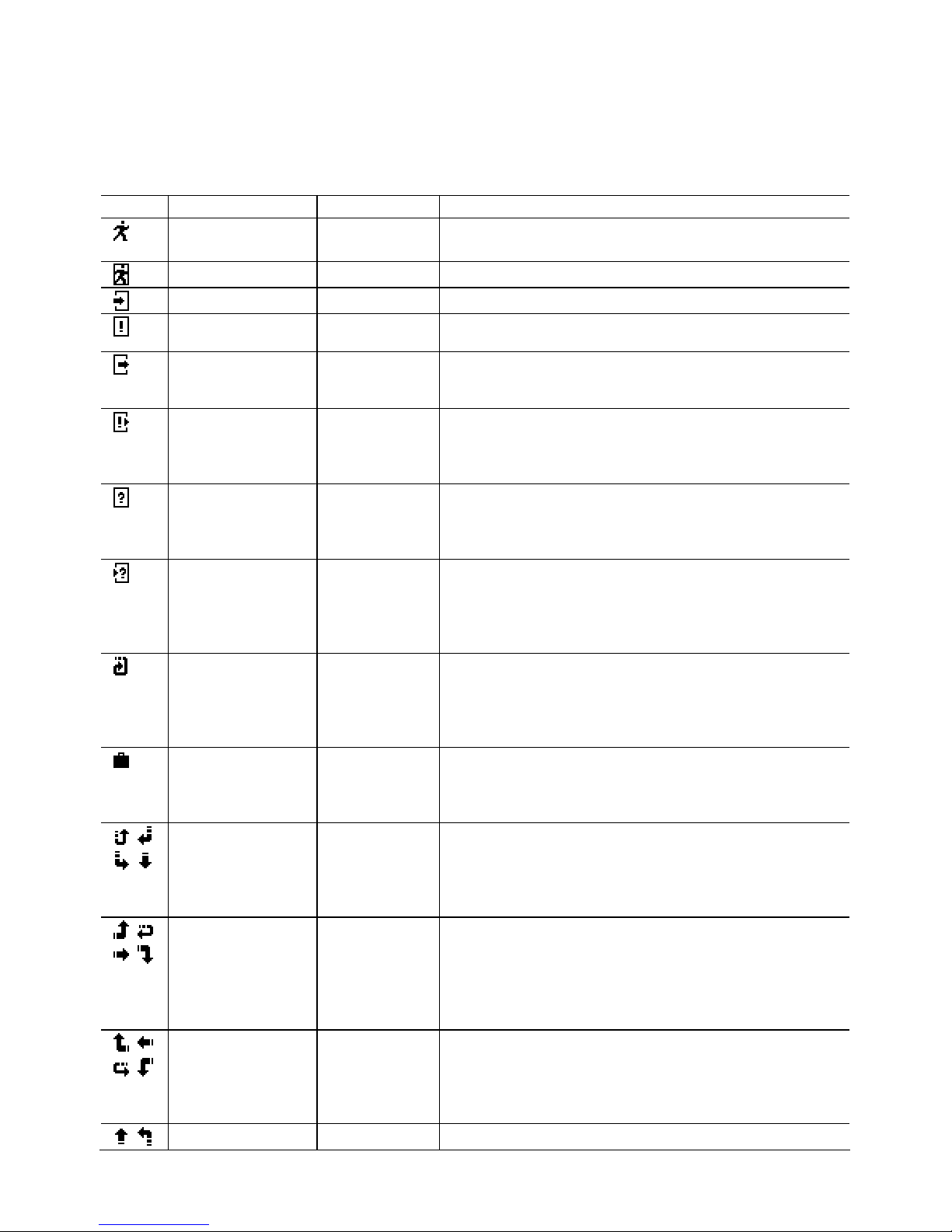
Ic
on Subject Range
Motion
Rect, Poly,
Line
Motion occurred.
Motion Inside
Rect, Poly
Motion occurred in the area.
Move Into
Rect, Poly
Object on outside moves into the area.
Appear Inside
Rect, Poly
Object which appeared inside.
*) Not supported in Simple mode.
Move Out
Rect, Poly
Object moves out.
*) Don’t use as a signal for starting video
recording.
Appe ared &
Move Out
Rect, Poly
Object which appeared inside, and moves out
*) Don’t use as a signal for starting video
recording.
*) Not supported in Simple mode.
Disappear
Inside
Rect, Poly
Object disappeared inside.
*) Don’t use as a signal for starting video
recording.
*) Not supported in Simple mode.
Moved In &
Disappear
Rect, Poly
Objects from outside, move into inside, and
disappears inside.
*) Don’t use as a signal for starting video
recording.
*) Not supported in Simple mode.
Loitering
Rect, Poly
Detect moving object within the zone during a
time.
*) Don’t use as a signal for starting video
recording.
*) Not supported in Simple mode.
Abandon/
Absent
Rect, Poly
Detect different region to stored background.
*) Don’t use as a signal for starting video
recording.
*) Not supported in Simple mode.
In & Out
Direction
Rect
Detect object moving. From top to enter of
area, detecting direction of moving out.
*) Don’t use as a signal for starting video
recording.
*) Not supported in Simple mode.
In & Out
Direction
Rect
Detect object moving. From right to enter of
area, detecting direction of moving out.
*) Don’t use as a signal for starting video
recording.
*) Not supported in Simple mode.
In & Out
Direction
Rect
Detect object moving. From left to enter of
area, detecting direction of moving out.
*) Don’t use as a signal for starting video
recording.
*) Not supported in Simple mode.
In & Out
Rect
Detect object moving. From bottom to enter of

Direction
area, detecting direction of moving out.
*) Don’t use as a signal for starting video
recording.
*) Not supported in Simple mode.
Move
Clockwise
Line
Event will occur the object moves in a
clockwise direction that start around.
*) Don’t use as a signal for starting video
recording.
Move ConterClockwise
Line
Event will occur the object moves in a counterclockwise direction that start around.
*) Don’t use as a signal for starting video
recording.
Path Event: Detect route between two zones (max. detection of 10 paths.)
NOTE:
* Disabled zone cannot be configured.
* Not supported in Simple mode.
* The path event detection can be inaccurate.
Output Direction Setup: Same as zone output configuration.
Clear All: All path combinations clear.
2) Env. Setup (Environment setup): Configurations for each PVA function.
- Md Sens (MD Sensitivity): Adjust motion sensitivity (HW sensitivity).
- Loiter Time (min): Time to judge if loitering object.
- Abandon/Absent Setup
Sens (Sensitivity): Adjust sensitivity of abandon/absent detection.
Det Time (min): Time to judge if absent/abandon area.
Rst Time (sec): Time to maintain event. After this time, background will update.
- Scn Chg Setup (Scene Change Setup)
Sens (Sensitivity): Adjust sensitivity of scene change detection.
Chg Ratio: Adjust judgment ratio of change from the stored background.
Det Time (sec): Time to judge scene changes.
Rst Time (sec): Time to maintain event. After this, background will update.
Unfocus: Detection on/off of unfocused state/defocused state.
- Windy Setup (Windy Area Detection Setup): Not applied in Simple PVA mode.
Sens (Sensitivity): Adjust sensitivity of windy object detection.
Det Time (sec): Time to judge if windy object.
Rst Time (sec): Time to release if windy object stays with no motion
3) Display Setup: Configuration for information on screen.
NOTE:
* Priority: Abandon/Absent > Loiter > Moving Object > Windy
* Same priority: large object size order
Alarm: Represent alarm icon on right-up side by of screen.
Counter: Represent counting on left-bottom (Det Only: When an event occurs).
Zone Area: Represent active zone.
Moving Object: Represent moving object with white rectangle.
Loitering: Represent loitering object with green rectangle.
Abandon/Absent: Represent abandon/absent area with wine colored rectangle.
Windy Area: Represent moving object with violet rectangle.
4) dTracking Setup: Configurations for digital Pan/Tilt/Zoom.
- 9 -
NOTE:

* Priority: Tracking priority: Zone > Loitering > Abandon/Absent > Obj.
* Maximum 4 objects can be represented.
* Same priority: Continuing detect. And Obj. > Size
- All Object: Tracking all detected objects.
- Loitering: Tracking detected loitering object.
- Abandon/Absent: Tracking detected absent/abandon area.
- Zone: When zone event occurs, tracking the area.
<Picture/DNR (Picture/Digital Noise Reduction)>
Menu for adjustment of video quality and DNR.
1) Sharpness: Adjust sharpness of outlines (0~15).
2) Enhancement: Select high resolution mode (Low/Mid/High).
3) 2D-NR: Adjust 2D-NR strength.
4) 3D-NR: Adjust 3D-NR strength. Remove noise by adding up several frames.
5) DNR Demo: Represent DNR effect. Left side is no DNR screen, right side shows
DNR screen.
6) Color Enh (Color Enhance): Adjust color strength.
<Effect>
1) Freeze: When [ENTER] key is pressed, still image is output on the screen.
2) d-Effect: Off/Rotation/Mirror/V Flip
3) Nega (Negative Picture): Inverse color effect.
4) DIS (Digital Image Stabilization): Compensation for image vibration.
Use of this function causes d-PTZ screen magnification to change.
5) dPTZ Preset: Configuration for d-PTZ preset. This will be applied when menu is
exited.
- Zoom: Adjust magnification.
- Pan&Tilt: Adjust Pan/Tilt position.
- Up/Down: Adjust tilt position.
- Left/Right: Adjust pan position.
6) i-Freeze: Select time of refresh rate for output video. This function is useful to reduce
the recording data storage. When motion is detected during i-Freeze, image is refreshed
to live mode. This is used not only to reduce the recording data but also not to miss
object movement.
- No Motion(s): Adjust Interval while no motion.
- Motion (0.1s): Adjust Interval while motion exists.
<System Setup>
1) General
- Cam Info: Display camera basic information.
NOTE:
* Cam ID/Baud rate/Protocol/Lens Type/CCD Type/Video System/Firmware Version
- System Lock: System locking by 4-character PID (Lock/Unlock).
- Change PID: Change PID used in the system lock.
NOTE:
* Enter PID: Input previous password. Default PID is “0000”.
* Enter New PID: Input new password.
* Retype New PID: Confirm new password.
- 10 -
- Title: Change camera title (max. of 8 characters).

- Display: Co
nfigurations for display camera ID & title.
Cam ID: Select camera ID display on/off.
Title: Select title display on/off.
Display Pos: Change position the string location.
- Language: Change menu OSD language.
2) Setup Tools
- System Config
Multi-Camset: Select On (user can use 4 configuration sets)/Off
Video Analytics: Select PVA mode. (Simple PVA/PVA+)
Communication: Configuration for RS-485.
Cam ID: Select the camera ID (001 - 255).
Baud Rate: Select serial communication speed (2400/4800/9600/19200).
Protocol: RS-485 protocol (Auto, FASTRAX/PELCO-D/PELCO-P).
Event Out: Off, Text-Out, FxLink
Event Strings: Select & edit sending strings for PVA/PVA+ Events.
NOTE:
* Text Out: Send event string through RS-485 line.
This function can work with IDIS DVRs Text-in feature.
* FxLink: Send event to PC application.
- WPC (White Pixel Compensation): Compensation for defective pixel on CCD.
NOTE:
* While operating in WPC, Iris will close automatically if using DC/IRIS lens; for manual lens,
block the lens hole.
Static/Auto: Automatic detecting of defective pixel and compensation.
Proceeding: Doing detection for white pixel.
NOTE:
* If brightness is too high, stop the process and print message “Bright Too High”.
* This function can compensate a max. of 63 points.
* If detected points are more than 63 points, repeats this detection by changes of conditions.
* If more than 63 points while changing conditions, stop the process and print “Too Many WH
Pixels”.
* User can stop the proceeding during operation.
Done: Complete white pixel detection.
View Detected WP: print detected pixel on screen.
Retry: Restart WPC process.
Accept: Store WPC result and return to previous menu.
Dynamic
Automated white pixel compensation for non-compensated pixels using static
method; no limits of compensation pixel number.
Select level (Low/Mid/High). Higher value setting compensates for more pixels.
NOTE:
* If the scene contains high frequency components, this can cause a loss.
Static/Manual: Manual white pixel compensation by appointment method.
Move Finder window using 4-arrow keys.
Marker: Expand finder window using digital zoom.
Move compensation pixel using 4-arrow keys.
Register: Adding compensation pixel.
- 11 -

NOTE:
* If registered points are more than 63 points, print “Memory Full” and stop action.
Marker: Use this if user sees other points.
Finder: Use this to move finder screen.
UnDo: Cancel the registered point.
Done: Return to previous menu.
Unregist: Deleting registered pixel.
NOTE:
* No more existing registered pixel; print “Memory empty” and stop action.
Marker: Select to continue unregistered action.
UnDo: Cancel the unregistered point.
Done: Return to previous menu.
Default: Recover to factory adjustment state.
- Focus Aid
To prevent the spread of light, AE mode changed to Shutter Fix Mode.
Min SHT (sec): Adjust minimum shutter speed.
Zoom: Zoom to focus window.
Adj: Adjust.
Start: Start measurement of maximum focus value.
Stop: Stop the measurement and initialize maximum focus value.
NOTE:
* FAD Max: Hold maximum focus value.
* FAD Val: Print present focus value.
* Usage:
Step 1: Point target to focus window.
Good target: higher contrast, more complex patterns.
Step 2: Minimize the spread of light by adjusting shutter speed.
Step 3: Turn the lens focus ring to end, start “Adj”.
Step 4: Turn the lens focus ring slowly to opposite side; record max focus value.
Step 5: If current fad value is lower than max fad value, stop turning focus ring.
Step 6: Adjust focus ring to be closer to the max fad value.
3) Lens : Select lens (DC lens/Video lens/Manual lens)
- Iris Speed: Adjust Iris speed (only for DC/Video Lens).
NOTE:
* If iris speed is too high, AE hunting can occur.
* If iris speed is too low, IRIS adjustment can operate too slowly.
4) LLC (Line Lock Control)
Active only when AC power is used. Select Int (Internal)/Ext (External) mode.
If mode is set to Ext, Sync Phase can be adjusted.
5) Day/Night
- Detection: Configure D/N change method (Internal/Fix-Day/Fix-Night/EXT-IN).
Internal: Operating DN changes with internal detection algorithm.
Fix-Day: Day mode fixed.
Fix-Night: Night mode fixed.
External: Work with EXT-IN mode. If port input voltage is high,
DN mode is Night; if port voltage is low, DN mode is Day.
- Burst: Select burst signal on/off in night mode.
- 12 -
- Dela
y (sec): Select delay time for D/N mode to change.

- D/N Threshold: Configure the thresh
old level for D/N mode to change
(Low/Mid/High/User).
NOTE:
* User Mode: Difference between D>N Level and N>D Level must be more than 2
and D>N must be less than N>D.
D>N: Adjust level of changing point of Day -> Night.
N>D: Adjust level of changing point of Night -> Day.
- OPD: Optical detector value. Represent present physical brightness.
- Use Alt Camset (N), Alt Camset: Select camera configuration set to apply in night
mode.
NOTE:
* Not supported in single Camset mode.
6) EXT-I/O
- D/N OUT (Day&Night Output): Select output method, No Func/D/N Out/AUX0.
AUX0: User defined output 0.
Set AUX0: Output voltage through to D/N OUT port [Open Collector (5V/10mA)].
- ALARM OUT: Select output method, No Func/Alarm Out/AUX1.
AUX1: User defined output 1.
Set AUX1: Output voltage through to D/N OUT port [Open Collector (5V/10mA)].
- D/N IN: Select input method, No Func/Alt Camset.
Alt. Camset: When inputting signal, change camera configuration.
Select Camset number.
7) Counter: Configurations for output of counting machine.
-
, : Represent counting value/adjust offset value.
- Alarm On Zero: When counter value reaches zero, camera will be alarmed.
Preset Cnt1, Cnt2: When counter reaches zero, counter value will be reset to this
value.
Reset: Initialize counter (Default Zero or Alarm on zero enabled: Offset Value).
TextOut to Comm: Event string sends through RS-485 lines.
NOTE:
* Event Out must be activated.
- 13 -

CONTROL AND CONNECTIONS OF TERMINALS
1 2 3 4 5 6 7 8
UTP-
(optional)
UTP+
(optional)
D&N
IN
D&N
OUT
COM
ALARM
OUT
RS-485+
(RX)
RS-485-
(TX)
1) UTP Connections/Video output (optional)
● 1 PIN: UTP-
● 2 PIN: UTP+
2) DAY&NIGHT I/O Terminals
To select Day/Night mode using external equipment, connect control lines to the appropriate
terminals.
● DAY&NIGHT OUTPUT (4 pin) – Open Collector (5V/10mA).
This is the camera function that can turn on an external IR LED Lamp by detecting the
sensitivity on the AGC level when the D&N mode is set "AUTO" on the OSD menu of the
camera
● DAY&NIGHT EXTERNAL INPUT (3 pin)
This is the camera function that can be switched to DAY Mode or NIGHT mode by
receiving the D&N on/off signal from external light sensor or IR LED LAMP. To work, this
needs the D&N Mode to be set to "External" on the OSD menu of the camera.
3) ALARM OUT (6 pin)
– Open Collector (5V/10mA).
Motion detection signals are output through this port. Active state is configurable.
4) POWER INPUT TERMINAL
● This terminal accepts a 12 VDC or 24 VAC
from a 12 VDC or 24 VAC (AC +/-10%
60/50Hz +/-1Hz) power source.
● Use Certified/Listed Class 2 power supply only.
● It is recommended to use a DC power supply that can support
inrush current over 0.55A.
● AC Power Cord - This power cord accepts 100-240V ~ 50Hz.
+/- 1Hz
5) CAMERA CONTROL
● 7 PIN: RS 485+
● 8 PIN: RS 485-
- 14 -
4 DAY&NIGHT OUTPUT
5 COM
5 COM
3 DAY&NIGHT INPUT
CLASS 2
+ DC 12V -
~ AC 24V ~
AC 100-240V
● 5V/10mA : IR LED ON (NIGHT)
● 0V : IR LED OFF (DAY)
Open contact: DAY
Close contact: NIGHT

LENS
The lens is not supplied with this camera. Purchase a lens suitable for your
requirements. These cameras accept both C- and CS-mount type lenses.
<Notes >
*) For using main functions it is recommended to use a DC-type auto iris lens.
If the lens is dirty with fingerprints or other marks, the image quality might be
poor.
<INSTALLING AUTO IRIS LENS>
1. Remove the cover from the iris lens plug supplied and solder the lens cable to the
plug as shown below.
*) It is recommended to use a high quality lens to improve the image quality
under low illumination.
● DC type:
Pin 1 --- Damping Pin 2 --- Damping+
Pin 3 --- Drive+
Connector
Cover
Heat
2. Remove the protective cap and attach the lens to the camera by turning clockwise.
Pin 4 --- Drive-
Shrinkable
Tubes
Au
tomatic
Iris Lens
Pin 3
Pin 1
Ir
is Control
Pin 4
Cable
Pin 2
Connector
- 15 -

SPECIFICATIONS
- 16 -
ITEM V662-D-1 V662-D-P-1 V662-D-1-PM
Input Voltage Dual (12 VDC, 24 VAC ±10%)
100-240V~50Hz±1Hz
Power Consumption 3.5 Watts (300mA) 4.0 Watts(55mA)
Power Connector 2-Pin Terminal Block Power Cord
VIDEO
Image Device 1/3" Sony Super-HAD II PS 960H CCD
Total Pixels 1020 (H) x 508 (V) 1020 (H) x 596 (V)
Effective Pixels 976 (H) x 494 (V) 976 (H) x 582 (V)
Scanning System 2:1 Interlace
Sync. System Internal/Line Lock (Phase Control)
Scanning Freq.
15.734KHz (H), 59.95Hz (V)
15.625KHz (H), 50Hz (V)
Horizontal Resolution 700 TVL
Min. illumination
0.1 Lux (Color), 0.01 Lux (BW), 0.0001 Lux (Sens-Up B/W) @ F/1.2, 50IRE
S/N (Y signal) More than 50dB
Video Output
CVBS 1.0Vp-p, 75Ω, UTP (Option)
OPERATIONAL
WDR x512 (Level Adjust), WDR-Full
White Balance
ATW/Wide, ATW/Indoor, ATW/Outdoor, Fix/Indoor, Fix/Outdoor,
Fix/FL, CRS, ATW Range Adjust
Exposure
Full Auto, Manual Shutter, Flickerless, Low Light (AGC, Sens-Up),
UDF (Ultra Deep Field)
Electronic Shutter
Speed
1/60 ~ 1/10,000
Auto: ~ 100,000
1/50 ~ 1/10,000
Auto: ~ 100,000
Dynamic Noise
Reduction
2D + 3D: Gain Adjust, DNR Demo
Day & Night Auto, Day, Night, Ext
Sens-up x256
Backlight Compensation EHLC, AUTO, SPOT
Motion Detection&
Video Analytics
PVA (Motion, Loitering, Abandon, Scene Change, Unfocus, Windy
Area)/Simple (Motion, Loitering, Abandon, Scene Change)
Digital Image Stabilizer OFF/ON
Privacy Masking Max 10 (4-point polygonal, Color, Transparency, Mosaic )
Digital Zoom x4 D-PTZ support
Digital Image Effect V-Flip, Mirror, Rotation, Nega & Posi, Freeze, Sharpness, Still Shot
Display
Camera Name: ON/OFF/Adjustable Location
Camera ID: ON/OFF/Adjustable Location
Language
English, German (TBD), French (TBD), Portuguese (TBD), Spanish
(TBD)
Camera ID 001 ~ 255
Camera Control Tact Switch, RS485
Protocol Auto, FASTRAX, PELCO-D, PELCO-P
ENVIRONMENTAL
Operating Temperature 14 º F ~ 122º F (-10º C ~ +50º C)
Operating Humidity 20 ~ 80% RH
MECHANICAL
Dimension/Weight
3.1 in. (78.8 mm) (W) x 2.5 in. (64 mm) (H)
x4.66 in. (118.4 mm ) (D)
/0.57 lb (260 g)
3.1 in. (78.8 mm) (W) x 2.5
in. (64 mm) (H)
x4.66 in. (118.4 mm ) (D)
/0.57 lb (260 g)
Lens Mount C/CS
Approvals
FCC (Class A), UL Listed
CE (Class A) Listed

MEMO

Shipping Instructions
Use the following procedure when returning a unit to the factory:
1. Call or write Vicon for a Return Authorization (R.A.) at one of the locations listed below.
Record the name of the Vicon employee who issued the R.A.
Vicon Industries Inc.
89 Arkay Drive
Hauppauge, NY 11788
Phone: 631-952-2288; Toll-Free: 1-800-645-9116; Fax: 631-951-2288
For service or returns from countries in Europe, contact:
Vicon Industries (U.K.) Ltd
Brunel W
ay
Fareham, PO15 5TX
United Kingdom
Phone: +44 (0)1489/566300; Fax: +44 (0)1489/566322
2. Attach a sheet of paper to the unit with the following information:
a. Name and address of the company returning the unit
b. Name of the Vicon employee who issued the R.A.
c. R. A. number
d. Brief description of the installation
e. Complete description of the problem and circumstances under which it occurs
f. Unit’s original date of purchase, if still under warranty
3. Pack the unit carefu
lly. Use the original shipping carton or its equivalent for maximum
protection.
4. Mark the R.A. number on the outside of the carton on the shipping label.

Vicon Standard Equipment Warranty
Vicon Industries Inc. (the “Company”) warrants your equipment to be free from defects in material and
workmanship under Normal Use from the date of original retail purchase for a period of three years, with the
following exceptions:
1. Monitors, all models: One year from date of original retail purchase.
2. Uninterruptible Power Supplies: Two years from date of original retail purchase.
3. VDR-700 Recorder Series: One year f
rom date of original retail purchase.
4. V5616MUX: One year from date of original retail purchase.
5. Arecont Cameras: One year from date of original retail purchase.
6. FMC series fiber-optic media converters and associated accessories: Lifetime warranty.
7. For PTZ cameras, “Normal Use” excludes prolonged use of lens and pan-and-tilt motors, gear
heads, and gears due to continuous use of “autopan” or “tour” modes of operation. Such
continuous operation is outside the s
cope of this warranty.
8. Any product sold as “special” or not listed in Vicon’s commercial price list: One year from date of
original retail purchase.
Date of retail purchase is the date original end-user takes possession of the equipment, or, at the sole
discretion of the Company, the date the equipment first becomes operational by the original end-user.
The sole remedy under this Warranty is that defective equipment be repaired or (at the Company’s option)
rep
laced, at Company repair centers, provided the equipment has been authorized for return by the
Company, and the return shipment is prepaid in accordance with policy.
The Company will not be obligated to repair or replace equipment showing abuse or damage, or to parts
which in the judgment of the Company are not defective, or any equipment which may have been tampered
with, altered, misused, or been subject to unauthorized repair.
Software supplied either
separately or in hardware is furnished on an “As Is” basis. Vicon does not
warrant that such software shall be error (bug) free. Software support via telephone, if provided at
no cost, may be discontinued at any time without notice at Vicon’s sole discretion. Vicon reserves
the right to make changes to its software in any of its products at any time and without notice.
This Warranty is in lieu of all other conditions and warranties express or implied as to
the Goods,
including any warranty of merchantability or fitness and the remedy specified in this Warranty is in
lieu of all other remedies available to the Purchaser.
No one is authorized to assume any liability on behalf of the Company, or impose any obligations on it in
connection with the sale of any Goods, other than that which is specified above. In no event will the
Company be liable for indirect, special, incidental, consequential, or other damages, whether arising
from
interrupted equipment operation, loss of data, replacement of equipment or software, costs or repairs
undertaken by the Purchaser, or other causes.
This warranty applies to all sales made by the Company or its dealers and shall be governed by the laws of
New York State without regard to its conflict of laws principles. This Warranty shall be enforceable against
the Company only in the courts located in the State of New York.
The form of this
Warranty is effective May 4, 2012.
THE TERMS OF THIS WARRANTY APPLY ONLY TO SALES MADE WHILE THIS WARRANTY IS IN
EFFECT. THIS WARRANTY SHALL BE OF NO EFFECT IF AT THE TIME OF SALE A DIFFERENT
WARRANTY IS POSTED ON THE COMPANY’S WEBSITE, WWW.VICON-SECURITY.COM. IN THAT
EVENT, THE TERMS OF THE POSTED WARRANTY SHALL APPLY EXCLUSIVELY.
Vicon Part Number: 8006-9010-03-10 Rev 0512


Vicon Industries Inc.
Corporate Headquarters
89 Arkay Drive
Hauppauge, New York 11788
631-952-2288 800-645-9116
Fax: 631-951-2288
Vicon Europe
Headquarters
Brunel Way
Fareham, PO15 5TX
United Kingdom
+44 (0) 1489 566300
Fax: +44 (0) 1489 566322
Vicon Germany
Kornstieg 3
D-24537 Neumuenster
Phone: +49 (0) 4321 8790
Fax: +49 (0) 4321 879 97
Far East Office
Unit 5, 17/F, Metropole Square
2 On Yiu Street, Shatin
New Territories,
Hong Kong
(852) 2145-7118
Fax: (852) 2145-7117
Internet Address: www.vicon-security.com
50303310B
 Loading...