


Installation and Operation Guide
XX235-01-01
V661-N Series High-Resolution
Vicon Industries Inc., 89 Arkay Drive, Hauppauge, New York 11788
Tel: 631-952-2288 Fax: 631-951-2288 Toll Free: 800-645-9116
24-Hour Technical Support: 800-34-VICON (800-348-4266) UK: 44/(0) 1489-566300
Vicon Industries Inc. does not warrant that the functions contained in this equipment will meet your requirements or that the
operation will be entirely error free or perform precisely as described in the documentation. This system has not been designed
to be used in life-critical situations and must not be used for this purpose.
Document Number: 8009-8235-01-01
Product specications subject to change without notice.
Analog Day/Night Camera
www.vicon-security.com
Issued: 513
Copyright © 2013 Vicon Industries Inc. All rights reserved.

-ii-
WARNING
CAUTION
CAUTION
CAUTION: TO REDUCE THE RISK OF ELECTRIC SHOCK,
DO NOT REMOVE COVER(OR BACK).
NO USER-SERVICEABLE PARTS INSIDE.
REFER SERVICING TO QUALIFIED SERVICE PERSONNEL.
EXPLANATION OF GRAPHICAL SYMBOLS
The lightning flash with arrowhead symbol, within an equilateral triangle, is
intended to alert the user to the presence of uninsulated "dangerous voltage"
within the product's enclosure that may be of sufficient magnitude to constitute a
risk of electric shock to persons.
The exclamation point within an equilateral triangle is intended to alert the user to
the presence of important operating and maintenance (servicing) instructions in the
literature accompanying the product.
Should any liquid or solid object fall into the cabinet,
unplug the unit and have it checked by the qualified
personnel before operating it any further.
Unplug the unit from the wall oulet if it is not going to
be used for several days or more. To disconnect the
cord, pull it out by the plug. Never pull the cord itself.
Allow adequate air circulation to prevent internal heat
build-up. Do not place the unit on surfaces (rugs,
blankets, etc.) or near materials(curtains, draperies)
that may block the ventilation holes.
Height and vertical linearity controls located at the
rear panel are for special adjustments by qualified
personnel only.
Do not install the unit in an extremely hot or
humid place or in a place subject to excessive
dust, mechanical vibration.
Clean the unit with a slightly damp soft cloth.
Use a mild household detergent. Never use
strong solvents such as thinner or benzine as
they might damage the finish of the unit.
Retain the original carton and packing
materials for safe transport of this unit in the
future.
Safety ----------------------------------------- Installation -----------------------------------
Cleaning --------------------------------------
PRECAUTIONS
TO REDUCE THE RISK OF FIRE OR ELECTRIC SHOCK, DO NOT EXPOSE THIS PRODUCT TO RAIN OR
MOISTURE. DO NOT INSERT ANY METALLIC OBJECTS THROUGH THE VENTILATION GRILLS OR
OTHER OPENINGS ON THE EQUIPMENT.

- iii -
FCC INFORMATION :
THIS EQUIPMENT HAS BEEN TESTED
AND FOUND TO COMPLY WITH THE LIMITS FOR A CLASS A DIGITAL
DEVICE, PURSUANT TO PART 15 OF THE FCC RULES. THESE
LIMITS ARE DESIGNED TO PROVIDE REASONABLE PROTECTION
AGAINST HARMFUL INTERFERENCE WHEN THE EQUIPMENT IS
OPERATED IN A COMMERCIAL ENVIRONMENT. THIS EQUIPMENT
GENERATES, USES, AND CAN RADIATE RADIO FREQUENCY
ENERGY AND IF NOT INSTALLED AND USED IN ACCORDANCE WITH
THE INSTRUCTION MANUAL, MAY CAUSE HARMFUL INTERFERENCE
TO RADIO COMMUNICATIONS. OPERATION OF THIS EQUIPMENT IN
A RESIDENTIAL AREA IS LIKELY TO CAUSE HARMFUL
INTERFERENCE IN WHICH CASE THE USER WILL BE
REQUIRED TO
CORRECT THE INTERFERENCE AT HIS OWN EXPENSE.
CAUTION :
CHANGES OR MODIFICATIONS NOT EXPRESSLY
APPROVED BY THE PARTY RESPONSIBLE FOR COMPLIANCE
COULD
VOID THE USER'S AUTHORITY TO OPERATE THE EQUIPMENT.
THIS CLASS A DIGITAL APPARATUS COMPLIES WITH CANADIAN
ICES-003.
NORME NMB-003 DU CANADA.
WARNING
THIS IS A CLASS A PRODUCT. IN A DOMESTIC ENVIRONMENT THIS
PRODUCT MAY CAUSE RADIO INTERFERENCE IN WHICH CASE
THE USER MAY BE REQUIRED TO TAKE ADEQUATE MEASURES.
CE COMPLIANCE STATEMENT
FCC COMPLIANCE STATEMENT

-iv-
IMPORTANT SAFETY INSTRUCTIONS
1. Read these instructions.
2. Keep these instructions.
3. Heed all warnings.
4 . Follow all instructions.
5. Do not use this apparatus near water.
6. Clean only with dry cloth.
7. Do not block any ventilation openings. Install in accordance with the
manufacturer's instructions.
8. Do not install near any heat sources such as radiators, heat registers,
stoves, or other apparatus (including amplifiers) that produce heat.
9. Do not defeat the safety purpose of the polarized or grounding-type
plug. A polarized plug has two blades with one wider than the other.
A grounding type plug has two blades and a third grounding prong.
The wide blade or the third prong are provided for your safety. If the
provided plug does not fit into your outlet, consult an electrician for
replacement of the obsolete outlet.
10.Protect the power cord from being walked on or pinched particularly
at plugs, convenience receptacles, and the point where they exit from
the apparatus.
11. Only use attachments/accessories specified by the manufacturer.
12. Use only with the cart, stand, tripod, bracket,
or table specified by the manufacturer,
or sold with the apparatus.
When a cart is used,use caution when moving
the cart/apparatus combination to avoid injury
from tip-over.
13. Unplug this apparatus during lightning storms or when unused for
long periods of time.
14. Refer all servicing to qualified service personnel. Servicing is
required when the apparatus has been damaged in any way, such as
power-supply cord or plug is damaged, liquid has been moisture, does
not operate normally, or has been dropped.
15. CAUTION THESE SERVICING INSTRUCTIONS ARE FOR USE BY
QUALIFIED SERVICE PERSONNEL ONLY. TO REDUCE THE RISK
OF ELECTRIC SHOCK DO NOT PERFORM ANY SERVICING OTHER
THAN THAT CONTAINED IN THE OPERATING INSTRUCTIONS
UNLESS YOU QRE QUALIFIED TO DO SO.
16. Use satisfy clause 2.5 of IEC60950-1/UL60950-1 or Certified/Listed
Class 2 power source only.

1
The camera provides high-quality images using Sony CCD technology especially
designed for closed-circuit television (CCTV) and security surveillance
applications.
Features:
INTRODUCTION
High resolution and high performance 1/3" Sony Super HAD
Technology
Excellent picture quality
600 lines(Color) of resolution
0.1 lux(Color), 0.04lux(B/W) @ F1.2 50IRE Sensitivity
Auto electronic shutter [1/60(1/50) ~ 1/100,000] and manual electronic
shutter modes
OSD (On Screen Display)
Auto and manual white balance modes
DWDR
OSD Font Color ( 16 Color)
BLC (Back Light Compensation)
Day&Night (Auto / DAY / NIGHT / EXT)
Private Mask (8 position, 16 Colors)
AGC (Auto Gain Control)
MIRROR (ON/OFF)
VIDEO OUT BNC
Motion Detection(4 point)
HLC (High Light Compensation)
DPC (Dead Pixel Cancellatin)
Operates in 100-240 VAC
Operates in AC24V +/- 10% / DC12V +/- 10%
TM
(
(
Model : V661-N-PM )
Model : V661-N / V661-N-P)
IMPORTANT : The user of this camera is responsible for
checking and complying with local, state, and federal laws
and statutes concerning the recording and monitoring of
audio signals.

Installation of the camera must be performed by qualified service personnel in accordance
with all local and national electrical and mechanical codes.
Carefully remove the color camera and its accessories from the carton
and verify that they were not damaged in shipment.
The contents of the package include:
Color CCD camera
Mini-DIN connector (for video-or dc-type auto-iris lens)
CS adapter ring for C mounting “C” lensesal
. This manual
1.
2.
3.
4
CONTENTS OF PACKAGE
2

CAMERA OVERVIEW
1-32UNEF
56 (2.2)
66 (2.6)
7 (0.27)
FRONT VIEW
BOTTOM VIEW
14 ( 0.55)
43 (1.7)
1/4-20UNC
SIDE VIEW
120 (4.7)
1
2
3
4
5
6
Left Button
Up Button
Enter Button
Right Button
Down Button
Power Indicator
Video Out Connector (BNC)
7
AC Power Cord
8
REAR VIEW
1
3
2
4
5
8
7
6
Unit: mm (inches)
1
2
3
4
5
6
Left Button
Up Button
Enter Button
Right Button
Down Button
Power Indicator
Video Out Connector (BNC)
7
AC/DC Compatible Input Terminal
8
1
3
2
4
5
8
7
6
Model : V661-N / V661-N-P
Model : V661-N-PM
3
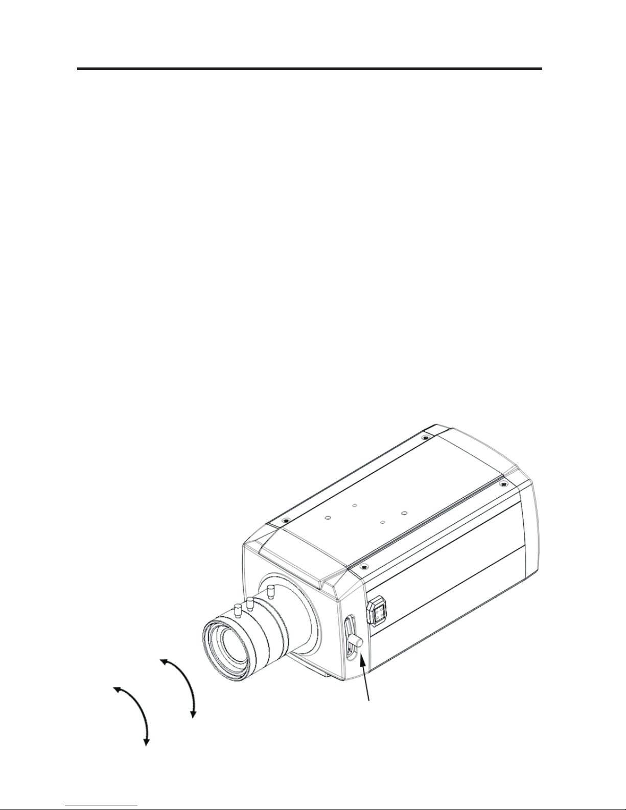
BACK FOCUS ADJUSTMENT
When installing a zoom lens on a camera, sometimes the lens cannot be focused at
either end of the zoom range. If this problem occurs, it may be necessary to adjust the
camera back focus. By adjusting the back focus, the position of the pick-up device in
relation to the rear of the lens is changing.
1. Secure the lens to the camera body, and plug in the auto iris connector.
2. Place a neutral density filter in front of the lens. This will force the lens iris to
open to the max. (In the case of a manual lens, open the lens iris to its maximum.)
3. Set the focus of the lens to full infinity.
4. Set the zoom to Wide.
5. Aim the camera at a high contrast object a distance away and move the back-focus
lever to bring object into focus.
6. Set the zoom to Tele.
7. Repeat the above steps until the focus remains clear throughout the zoom range
<PROCEDURE>
4
Back-focus lever
Focus
Zoom

THE DEFINITION OF TERMS
White Balance
Exposure
SHUTTER (Electronic Shutter)
Flicker (FLC)
AGC (Automatic Gain Control)
Back Light Compensation (BLC)
HLC (High Light Compensation)
LENS SHAD. (Lens Shading)
Mask
Detection
Sharpness
Compensates for deviations in the white color caused by changes in the color
temperature of the light source so that the colors are reproduced correctly.
Adjusts the images to the optimum brightness.
Controls the integration time (exposure) of the photodiode array and reduces blooming,
overexposure, and smear when capturing moving objects.
Avoids image flicker when there is a discrepancy between current and frequency
Automatically adjusts (boosts) the video signal to the required level to produce a quality
image in low light situations
Compensates for the brightness of the subjects with a large amount of background light
that would make it practically impossible to see any details of the subjects. Adjusts the
iris so that a distinctive subject and the background are delivered at the same time.
When a high-brightness subject is shot, it may not be brought into focus because of the
large surface area over which the high-brightness pixels are spread.
In cases like this, the high-brightness subject can be brought into focus by using this
function.
This function is the make brighter image of corner of screen.
Hides one or more areas that the user does not want to be displayed on screen.
Masks can be set with their own display area, color, darkness and mosaic processing.
Detects motion within the scene using one of the available methods.
Some methods trigger the Alarm output.
Reducing this parameter adjusts the noise level to smooth out the "noise" caused by
the compression.
Caution should be taken not to reduce it too much, which may result in a blurred image.
5

Resolution
2D-NR (Digital Noise Reduction)
Nega
DPC(Dead Pixel Cancellation)
MIRROR
DWDR
PARK. LINE
FONT COLOR
Controls the display of fine details. The higher the resolution, the higher level of
details can be seen.
Adjusts the illuminance noise level in low light situations by reducing image noise in
order to improve the image.
Reverses the color signals for the Chroma signal so the image looks like a “negative.”
white pixels whose frequency of occurrence varies in proportion to the temperature
are sometimes observed when the devices are used under the influence of external
factors or especially high temperatures. The white pixel detection and compensation
function can automatically detect and compensate up to 64 white pixels with the highest
detection level in sequence so as to maintain the image quality.
Reverses the image on the screen left to right or right to left
(as it would be seen in a mirror.)
When the camera looks at a dark area, there may be loss of dark detail in the
low-brightness subjects.
Using DWDR (on) may produce a higher quality image.
Using the camera to look out the rear of a vehicle, a lane can be viewed on the video
image to see anything directly behind the vehicle. The location and size of the lane can
be adjusted through the menu: LT/LB: left top/bottom; RT/RB: right top/bottom;
F: far; N: near; T: thickness of the line.
Adjust OSD menu color from a choice of 16 different colors.
6

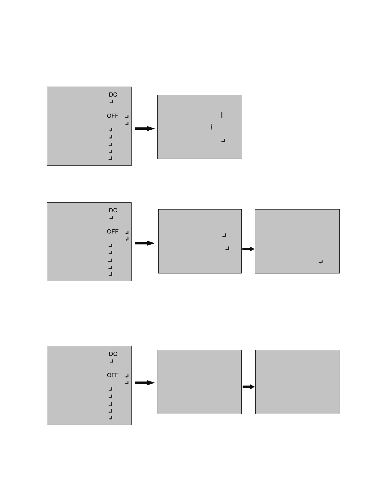
STRUCTURE OF THE SETUP MENU
<SETUP>
LENS
EXPOSURE
WHITE BAL
BACKLIGHT
DAY NIGHT
DPC
SPECIAL
IMAGE ADJ
RESET
EXIT
<LENS>
DC
MANUAL
<EXPOSURE>
SHUTTER
BRIGHTNESS
AGC
RETURN
DWDR
<>WHITE BAL <DAY NIGHT>
AUTO
COLOR
B/W
EXT
<SPECIAL>
CAM TITLE
MOTION
PRIVACY
PARK.LINE
LANGUAGE
RETURN
<IMAGE ADJUST>
LENS SHAD.
2DNR
MIRROR
FONT COLOR
CONTRAST
SHARPNESS
DISPLAY
NEG.IMAGE
RETURN
<RESET>
FACTORY
RETURN
ATW1
ATW2
AWC->SET
MANUAL
7
<>BACKLIGHT
OFF
BLC
HLC
<DPC>
COVER THE LENS
THEN
PRESS ENTER KEY

This function is used to adjust the brightness of the screen.
1. When the SETUP menu is displayed on the screen, please position the arrow to point to
'LENS' by using the UP and DOWN buttons.
2. Please select the type of the lens you wish to use by pressing the LEFT or RIGHT button.
LENS (Selection)
►
Note The brightness of the screen can be adjusted in DC mode.
EXPOSURE
EXPOSURE
SHUTTER AUTO
BRIGHTNESS 50
AGC ---D-WDR OFF
RETURN RET
IIIIIIIIIIIIIIIIII
The EXPOSURE menu is used to set the automatic light control method for this camera.
(Xtended Dynamic Range)
1) SHUTTER
2) BRIGHTNESS
3) AGC
4) DWDR
Select the shutter mode.(Auto,1/60(50), FLK~ 1/100,000 sec)
Can be changed while in shutter mode.
Adjust BRIGHTNESS level (0 ~ 255)
Can be adjusted while in DC/ manual lens mode.
Auto gain control (OFF / LOW / MIDDLE / HIGH)
Digital Wide dynamic range
OFF / ON
8
ATW1
AUTO
►
MANUAL
LENS
EXPOSURE
WHITE BAL
BACKLIGHT
DAY NIGHT
DPC
SPECIAL
IMAGE ADJ
RESET
EXIT
LENS
EXPOSURE
WHITE BAL
BACKLIGHT
DAY NIGHT
DPC
SPECIAL
IMAGE ADJ
RESET
EXIT
ATW1
AUTO
OFF
►
ATW1
AUTO
LENS
EXPOSURE
WHITE BAL
BACKLIGHT
DAY NIGHT
DPC
SPECIAL
IMAGE ADJ
RESET
EXIT

WHITE BAL
<WHITE BAL MANUAL MODE>
WHITE BAL MANUAL
COLOR TEMP OUTDOOR
BLUE -----------RED -----------RETURN RET
►
The screen color can be adjusted by using the WHITE BALANCE function.
1) ATW1
2) ATW2
3) AWC -> SET
4) MANUAL
Set the color temperature 2500 K 10000 K
Set the color temperature 2000 K 13000 K
Please press the ENTER button while the camera is directed
at a piece of white paper to obtain the optimum state under
current illumination. if the environment including the light source
is changed, you have to adjust the white balance again.
Manual mode. User can change R and B Gain manually.
INDOOR Set the color temperature to 3200 K
OUTDOOR Set the color temperature to 6300 K
oo
oo
o
o
BACKLIGHT BLC
AREA SEL AREA1
AREA STARE ON
GAIN 042
HEIGHT 005
WIDTH 004
LEFT/RIGHT 005
TOP/BOTTOM 005
RETURN RET
IIIIIIIIIIIIIIIIII
IIIIIIIIIIIIIIIIII
IIIIIIIIIIIIIIIIII
IIIIIIIIIIIIIIIIII
IIIIIIIIIIIIIIIIII
BACKLIGHT HLC
LEVEL
IIIIIIIIIIIIIIIIII
200
MODE NIGHT ONLY
RETURN RET
< MODE>BACKLIGHT
BACKLIGHT
1) BLC
2) HLC
Prevents such a back light effect to secure a clear image under all
illumination environments
The function improves the identification capability of subjects facing a
brightly lit situation by filtering out the strength of the light
9
►
ATW1
AUTO
LENS
EXPOSURE
WHITE BAL
BACKLIGHT
DAY NIGHT
DPC
SPECIAL
IMAGE ADJ
RESET
EXIT
►
ATW1
AUTO
LENS
EXPOSURE
WHITE BAL
BACKLIGHT
DAY NIGHT
DPC
SPECIAL
IMAGE ADJ
RESET
EXIT
10
<DAY NIGHT AUTO MODE>
DAY NIGHT
DAY NIGHT AUTO
D -N LEVEL 128
D
RETURN RET
IIIIIIIIIIIIIIIIII
IIIIIIIIIIIIIIIIII
-N DELAY 5 SEC
N-D LEVEL 003
N-D DELAY 5 SEC
►
DAY NIGHT B/W
BURST OFF
IR SMART
RETURN
RET
ON
IR LEVEL HIGH
►
IR SMART
IR GAIN
HEIGHT
RETURN RET
IIIIIIIIIIIIIIIIII
IIIIIIIIIIIIIIIIII
IIIIIIIIIIIIIIIIII
IIIIIIIIIIIIIIIIII
IIIIIIIIIIIIIIIIII
074
007
WIDTH 008
LEFT/RIGHT 003
TOP/BOTTOM 004
►
<DAY NIGHT B/W MODE>
DPC
DPC Auto setting (Dead pixels are automatically removed)
DPC
COVER THE LENS
THEN
PRESS ENTER KEY
►
PROCESSING NOW
►
ATW1
AUTO
LENS
EXPOSURE
WHITE BAL
BACKLIGHT
DAY NIGHT
DPC
SPECIAL
IMAGE ADJ
RESET
EXIT
►
ATW1
AUTO
LENS
EXPOSURE
WHITE BAL
BACKLIGHT
DAY NIGHT
DPC
SPECIAL
IMAGE ADJ
RESET
EXIT
►
ATW1
AUTO
LENS
EXPOSURE
WHITE BAL
BACKLIGHT
DAY NIGHT
DPC
SPECIAL
IMAGE ADJ
RESET
EXIT
The DAY/NIGHT menu is used to configure the day and night related setting for this camera.
This camera can turn the IR(infrared)filter on or off.
Mode : AUTO / COLOR / B/W / EXT (The EXT is not operating in this mode)
* The IR LEVEL is not operating in DAY NIGHT B/W mode.

1) CAM TITLE
Select MD area number. (AREA1 ~AREA4)
Select MD ON/OFF
Adjust height of MD area
Adjust width of MD area
Adjust the location of the MD area with boundary LEFT and RIGHT.
Adjust the location of the MD area with boundary TOP and BOTTOM
Adjust sensitivity of MD area.(0~255)
The screen displays with pink dots. When a motion is detected
in the selected area, the pink dots are displayed on the screen.
2) MOTION
AREA SELECT
AREA STATE
HEIGHT
WIDTH
LEFT/RIGHT
TOP/BOTTOM
DEGREE
VIEW
A.
B.
C.
CAM TITLE
Character Table
Command Line
: Move to left
: Move to right
CLR : Erase all characters
POS : Move the position of title
END : Save and End
←
→
SPECIAL
►
MOTION
AREA SELECT AREA1
AREA STATE ON
WIDTH
HEIGHT 4
4
LEFT/RIGHT
2
TOP/BOTTOM
2
DEGREE
38
VIEW
OFF
RETRURN
RET
IIIIIIIIIIIIIIIIII
IIIIIIIIIIIIIIIIII
IIIIIIIIIIIIIIIIII
IIIIIIIIIIIIIIIIII
IIIIIIIIIIIIIIIIII
►
A
B
C
CAM TITLE
←→ CLR POS END
SPECIAL
CAM TITLE
MOTION
PRIVACY
PARK.LINE
LANGUAGE
RETURN
ON
ON
OFF
OFF
ENGLISH
RET
.
►
ATW1
AUTO
LENS
EXPOSURE
WHITE BAL
BACKLIGHT
DAY NIGHT
DPC
SPECIAL
IMAGE ADJ
RESET
EXIT
11

3) PRIVACY
AREA SELECT
AREA STATE
HEIGHT
WIDTH
LEFT/RIGHT
TOP/BOTTOM
COLOR
RETURN
4) PARK.LINE
5) LANGUAGE
6) RETURN
Select MASK area number.(Area 1 ~ Area 8)
Select MASK ON/OFF
Adjust height of MASK area
Adjust width of MASK area
Adjust the location of the MASK area with boundary LEFT and RIGHT
Adjust the location of the MASK area with boundary
TOP and BOTTOM.
Select MASK color. (0~15)
Select Parking area
ENGLISH or CHINESE
RET
PRIVACY
AREA SELECT AREA1
AREA STATE
ON
RETURN
RET
HEIGHT 032
WIDTH 032
LEFT/RIGHT 020
TOP/BOTTOM 030
COLOR 000
IIIIIIIIIIIIIIIIII
IIIIIIIIIIIIIIIIII
IIIIIIIIIIIIIIIIII
IIIIIIIIIIIIIIIIII
IIIIIIIIIIIIIIIIII
►
<PRIVACY MODE>
►
SPECIAL
CAM TITLE
MOTION
PRIVACY
PARK.LINE
LANGUAGE
RETURN
OFF
OFF
ON
OFF
ENGLISH
RET
PARK LINE
LT 077
LB 029
RT
RB
F
N
T
RET
.
►
122
170
013
058
009
►
ATW1
AUTO
LENS
EXPOSURE
WHITE BAL
BACKLIGHT
DAY NIGHT
DPC
SPECIAL
IMAGE ADJ
RESET
EXIT
►
SPECIAL
CAM TITLE
MOTION
PRIVACY
PARK.LINE
LANGUAGE
RETURN
OFF
OFF
ON
OFF
ENGLISH
RET
12

< MODE>IMAGE ADJUST
LENS SHAD
LEVEL
RETURN RET
006
IIIIIIIIIIIIIIIIII
►
►
LENS SHAD
2DNR
MIRROR
FONT COLOR
CONTRAST
SHARPNESS
DISPLAY
NEG.IMAGE
RETURN
IIIIIIIIIIIIIIIIII
IIIIIIIIIIIIIIIIII
122
21
ON
ON
OFF
IMAGE ADJUST
OFF
CRT
FONT COLOR
FONT
RETURN RET
003
ID&TITLE 003
IIIIIIIIIIIIIIIIII
IIIIIIIIIIIIIIIIII
►
►
LENS SHAD
2DNR
MIRROR
FONT COLOR
CONTRAST
SHARPNESS
DISPLAY
NEG.IMAGE
RETURN
IIIIIIIIIIIIIIIIII
IIIIIIIIIIIIIIIIII
122
21
ON
ON
OFF
IMAGE ADJUST
OFF
CRT
IMAGE ADJUST
1) LENS SHAD
2) 2DNR
3) MIRROR
4) FONT COLOR
5) CONTRAST
6) SHARPNESS
7) DISPLAY
8) NEG. IMAGE
Adjust Lens shading level (0~255)
Select 2DNR ON/OFF
Select MIRROR ON/OFF
Select FONT COLOR level (0~15)
Select IDR TITLE level (0~15)
Adjust CONTRAST level (0~255)
Adjust SHARPNESS level (0~31)
Select DISPLAY mode (CRT /LCD/USER)
Select Negative image mode ON /OFF
RET
RET
13

14
1) FACTORY Returns to the level which was set by the manufacturer for shipment.
RESET
EXIT
1) EXIT Saves all setting and exits.
CRT ADJUST
PED LEVEL
192
RETURN RET
022
COLOR GAIN
IIIIIIIIIIIIIIIIII
IIIIIIIIIIIIIIIIII
►
►
LENS SHAD
2DNR
MIRROR
FONT COLOR
CONTRAST
SHARPNESS
DISPLAY
NEG.IMAGE
RETURN
IIIIIIIIIIIIIIIIII
IIIIIIIIIIIIIIIIII
122
21
ON
ON
OFF
IMAGE ADJUST
OFF
CRT
LCD AJUST
GAMMA
160
RETURN
RET
0.50
PED LEVEL
028
COLOR GAIN
IIIIIIIIIIIIIIIIII
IIIIIIIIIIIIIIIIII
►
USER AJUST
GAMMA
160
RETURN RET
0.45
PED LEVEL 028
COLOR GAIN
IIIIIIIIIIIIIIIIII
IIIIIIIIIIIIIIIIII
►
RET

15
2) VIDEO OUT CONNECTOR
BNC : This BNC connector provides a 1.0Vp-p/75 ohms composite video Signal.
POWER INPUT TERMINAL AND VIDEO OUT
CONNECTOR
Use Certified/Listed Class 2 power supply only.
AC 100-240V
AC Power Cord - This power cord accepts a
100-240V ~ 50/60Hz +/- 1Hz
CLASS 2
+ DC 12V -
~ AC 24V ~
This terminal accepts a DC12V or AC24V power
source from a DC12V or AC24V ac +/-10% 60/50Hz +/- 1Hz.
Use Certified/Listed Class 2 power supply only.
In DC power, use the Adapter mode than DC 12V
500mA Capacity.
1) POWER INPUT TERMINAL
Model : V661-N / V661-N-P
Model : V661-N-PM

The lens is not supplied with this camera. Purchase a lens suitable for your environment.
This camera accepts the auto iris lens and both C-and CS-mount lens.
Connector
Cover
Iris Control
Cable
Connector
Automatic
Iris Lens
Heat
Shrinkable
Tubes
2. Remove the protective cap, and attach the lens to the camera by turning clockwise.
LENS
For using main functions it is recommended to use Auto Iris Lens with DC type.
If the lens is marked with fingerprints other marks, the image quality might be poor.
It is recommended to use a high quality lens to improve the image quality under
low illumination.
<INSTALLING AUTO IRIS LENS>
1. Remove the cover from the iris lens plug supplied, and solder the lens cable to the plug as
shown below.
DC type :
Pin 1 --- DampingPin 2 --- Damping+
Pin 3 --- Drive+
Pin 4 --- Drive-
* Notes *
16

SPECIFICATIONS
Power source
Power consumption
Image sensor
Total pixels
Scanning system
Scanning frequency
Sync. system
Resolution
Min. illumination
Power input
Auto iris output
2:1 interlace
15.734KHz(H) x 59.94Hz(V)
Internal
600 TV lines (Color)
0.1 Lux(Color), 0.04 Lux(B/W) @ F1.2, 50IRE
795(H) x 595(V)
C/CS Mount (Selected through back focus)
V661-N
811(H) x 507(V)
MODEL
Day & Night
Parking Line
Font Color
Sharpness
Display
2DNR
Nega Image
Language
Power
15.625KHz(H) x 50Hz(V)
Connector
&
etc.
Contrast
Video output
Operating temperature
Operating humidity
FONT 16 COLOR, ID&TITLE 16 COLOR
4-Pin Mini Din jack (standard connection)
0 ~ 96% (non-condensing)
General
Lens Shading
OFF / LOW / MIDDLE / HIGH
FACTORY RESET / RETURN
Lens Mount
External Dimension
Weight
BNC connector
1/4"-20 UNC (top or bottom)
66(W) x 63(H) x 120(D) mm
F
U
N
C
T
I
O
N
400g
Electronic Shutter
1/60 ~ 1/100,000 sec.
1/50 ~ 1/100,000 sec.
Video Output
S/N Ratio
Camera Control
OSD (Tact Switch)
More than 50dB (AGC off)
1.0 Vp-p (75 ohm, Composite)
Lens
Shutter
Brightness
AGC
MANUAL / DC
AUTO, 1/60(1/50), Flickeless, 1/250 ~ 1/100,000sec
0 ~255
OFF / BLC / HLC(High Light Compensation)
Backlight
DWDR
OFF/ON
White Balance
AUTO/COLOR/B&W/EXT
S
P
E
C
I
A
L
D&N
B/
W
Burst
IR Smart
IR Level
OFF/ON
OFF/ON
OFF/ON(4area)
OFF / ON (8 position )
OFF/ON
LOW/HIGH
Camera Title
Motion Detection
Privacy Masking
Mirror
OFF/ON
OFF / ON (0~255)
OFF/ON
OFF/ON
0~255
0~31
OFF/ON
CRT/LCD/USER
ENGLISH / CHINESE
Dead Pixel Cancellation (Auto 64 Points)
DPC
Reset
Mounting Hole
14 F ~ 122 F (-10 C ~ +50 C)
ooo o
1/ " CCD3 SONY Super HAD
ATW1 / ATW2 / MANUALAWC->SET /
17
V661-N P
-
AC24V ± 10% / DC12V ± 10%
200mA (2.5 Watts)
2-pin terminal block
V661-N PM
-
30mA (2.5 Watts)
100 -240V ~50/60Hz +/- 10%
Power Cord
450g


50303036A
 Loading...