


X971
Surveyor Mini Dome System
Vicon Industries Inc. does not warrant that the functions contained in this equipment will meet your requirements
or that the operation will be entirely error free or perform precisely as described in the documentation. This
system has not been designed to be used in life-critical situations and must not be used for this purpose.
Copyright © 1998 Vicon Industries Inc. All rights reserved.
Product specifications subject to change without notice.
Vicon and its logo are registered trademarks of Vicon Industries Inc.
Vicon Part No. 8006-8971-03-00 Section 1 Rev 1098
VICON INDUSTRIES INC., 89 ARKAY DRIVE, HAUPPAUGE, NEW YORK 11788
TELEPHONE: 516-952-CCTV (2288) FACSIMILE: 516-951-CCTV (2288)
TOLL FREE: 800-645-9116 UK: 44/(0) 1489-566300 INFOFAX: 800-287-1207


Dear Valued Customer:
Thank you for selecting Vicon systems and products for your
video needs.
Since Vicon’s beginning in 1967, our only business has been the
design, engineering, and production of the highest quality video systems
and equipment for use in a wide variety of security, safety, control,
surveillance, and communication applications.
We stand behind the quality and dependability of every product
with an industry leading Beneficial Use warranty.
If you are not satisfied with a Vicon product or service, I would
like to know. Your complete satisfaction is the mission of every Vicon
employee.
Sincerely,
Kenneth M. Darby
President


FCC Notice
NOTE: Complies with Federal Communications Commission Rules & Regulations Part 15, Subpart B for a
Class A digital device.
WARNING
This equipment generates and uses radio frequency energy and if not installed and used properly, that is, in
strict accordance with the manufacturer’s instruction, may cause interference to radio and television
reception. It has been type tested and found to comply with the limits for a Class A computing device in
accordance with the specification in subpart B of part 15 of the FCC rules, which are designed to provide
reasonable protection against such interference in a commercial installation. However, there is no guarantee
that interference will not occur in a particular installation. If this equipment does cause interference to radio
and television reception, which can be determined by turning equipment off and on, the user is encouraged to
try and correct the interference by one or more of the following measures:
• Reorient the receiving antenna.
• Relocate the equipment with respect to the receiver.
• Relocate the equipment away from the receiver.
• Plug the equipment into a different electrical outlet so that the equipment and receiver
are on different branch circuits.
If necessary, the user should consult the dealer or an experienced radio/television technician for additional
suggestions.
The user may find the following booklet prepared by the Federal Communications Commission helpful:
“Interference Handbook, Bulletin CIB-2”
This booklet is available from the U.S. Government Printing Office, Superintendent of Documents, Mailstop
SSOP, Washington, D.C. 20402-9328, ISBN 0-16-045542-1.
WARNING: Power must be removed from this unit before removing circuit modules or Ribbon Cables.
CAUTION: This unit contains circuit cards with integrated circuit devices that can be damaged by static
discharge. Take all necessary precautions to prevent static discharge.


Contents
INTRODUCTION...................................................................................................................1
Unpacking and Inspection.............................................................................................................................1
Inspection for Visible Damage......................................................................................................................1
Inspection for Concealed Damage ...............................................................................................................1
Housings .........................................................................................................................................................2
Drive Mechanism Assembly..........................................................................................................................2
Camera/Lens Module .....................................................................................................................................2
Lower Dome ....................................................................................................................................................2
V7UFR Fire-Resistant Shield.........................................................................................................................2
DRIVE MECHANISM ASSEMBLY .......................................................................................3
Installing the Camera/ Lens Module .........................................................................................................3
Switch Settings and Adjustments..............................................................................................................3
Setting the Service Switch ............................................................................................................................4
HOUSING INSTALLATION ..................................................................................................7
INDOOR PENDANT ..................................................................................................................8
Installation Using a Vicon Mount...............................................................................................................8
Installation Using a 1.5-inch Pipe..............................................................................................................9
DROPPED CEILING ............................................................................................10
Installation into a Dropped Ceiling ..........................................................................................................10
X971 Rev 1098 Surveyor Mini Dome System Contents • i

SOLID CEILING ............................................................................................................ 12
Installation Into a Solid Ceiling ............................................................................................................... 12
OUTDOOR PENDANT ................................................................................................ 13
Installation Using a Vicon Mount ............................................................................................................ 13
Installation Using a 1.5-inch Pipe ........................................................................................................... 14
WIRING .............................................................................................................................. 15
Installing the Cables ...............................................................................................................................17
FINAL ASSEMBLY ............................................................................................................ 19
Installing the Drive Mechanism............................................................................................................... 19
Installing the Domes ............................................................................................................................... 20
For Indoor Pendant Installations............................................................................................................. 20
For Dropped Ceiling Installations ........................................................................................................... 21
For Solid Ceiling Installations ................................................................................................................. 21
For Outdoor Pendant Installations.......................................................................................................... 21
DISASSEMBLING THE MINI DOME ................................................................................. 23
If It It Is Necessary to Remove the Trim Ring......................................................................................... 24
OPERATION ...................................................................................................................... 25
Initial Power-Up ...................................................................................................................................... 25
Verifying Proper Operation......................................................................................................................... 26
Running the Diagnostic Test ..................................................................................................................27
MAINTENANCE ................................................................................................................. 29
CARE AND CLEANING OF METALLIZED DOMES.................................................................................... 29
CARE AND CLEANING OF CLEAR ACRYLIC DOMES ............................................................................. 29
Fuse Replacement ....................................................................................................................................... 29
SHIPPING INSTRUCTIONS............................................................................................... 31
REFERENCE ..................................................................................................................... 33
ii • Contents X971 Rev 1098 Surveyor Mini Dome System

Coaxial Cable ................................................................................................................................................33
Twisted-Pair Cable .......................................................................................................................................34
1.5-inch Pipe Designation............................................................................................................................34
TECHNICAL INFORMATION .............................................................................................35
X971 Rev 1098 Surveyor Mini Dome System Contents • iii

iv • X971 Rev 1098 Surveyor Mini Dome System

List of Figures and Tables
Figure 1
Basic Surveyor Unit ...........................................................................................................................................1
Figure 2
Camera/ Lens and Ribbon Cable Assembly....................................................................................................3
Figure 3
Assembly Side View ..........................................................................................................................................3
Figure 4
Location of DIP Switches S2 and S5................................................................................................................3
Table 1
DIP Switch 5 (S5) Settings ................................................................................................................................4
Table 2
DIP Switch 2 (S2) Settings ................................................................................................................................5
Figure 5
Exploded view - Indoor Pendant and Vicon Mount ........................................................................................8
Figure 6.
Installation on a Vicon Mount ...........................................................................................................................8
Figure 7
Exploded view - Indoor Pendant and Pipe Mount ..........................................................................................9
Figure 8
Installation on a 1.5-inch Pipe ..........................................................................................................................9
Figure 9
Exploded View - Dropped Ceiling ..................................................................................................................10
Figure 10
Installation in a Dropped Ceiling ....................................................................................................................10
Figure 11
Cable Access Cap............................................................................................................................................11
Figure 12
Dropped Ceiling Mount Adjustments.............................................................................................................11
Figure 13
Exploded View - Solid Ceiling.........................................................................................................................12
Figure 14
Cable Access Cap............................................................................................................................................12
Figure 15
Exploded View - Outdoor Pendant .................................................................................................................13
Figure 16
Installation on a 1.5 inch Pipe.........................................................................................................................13
Figure 17
Exploded View - Outdoor Pendant 1.5 inch Mount ......................................................................................14
Figure 18
Installation on a 1.5 inch Pipe.........................................................................................................................14
Table 3
Required Control Signals for Specific Communication Modes ..................................................................15
Figure 19
Typical Alarm Circuit .......................................................................................................................................16
Figure 20
Typical Auxiliary Output..................................................................................................................................16
Figure 21
Customer Interface Board...............................................................................................................................17
X971 Rev 1098 Surveyor Mini Dome System List of Figures and Tables • v

Table 4
Customer Interface Board Terminal Block Definitions................................................................................ 18
Figure 22
Drive to Housing Alignment ........................................................................................................................... 19
Figure 23
Exploded View - Drive Installation................................................................................................................. 19
Figure 24
Exploded View - Indoor Dome Installation.................................................................................................... 20
Figure 25
Exploded View - Outdoor Dome Installation ................................................................................................ 21
Figure 26
Drive Release Handle ...................................................................................................................................... 23
Figure 27
Trim Ring Removal.......................................................................................................................................... 24
Figure 28
Power-Up Test Screen .................................................................................................................................... 25
Figure 29
Opening Screen ............................................................................................................................................... 25
Figure 30
Main Menu ........................................................................................................................................................ 26
Table 5
Diagnostic Functions Routine........................................................................................................................ 27
Table 6
Recommended Coaxial Cable Types............................................................................................................. 33
Table 7
Recommended Individually-Shielded, Twisted-Pair Cable Types.............................................................. 34
Table 8
Applicable Wire Size ....................................................................................................................................... 35
Table 9
Surveyor Components ....................................................................................................................................38
Table 10
Surveyor Overall Dimensions ........................................................................................................................38
vi • X971 Rev 1098 Surveyor Mini Dome System

Important
Safeguards
GRAPHIC SYMBOL EXPLANATION
The lightning flash with arrowhead symbol, within an
equilateral triangle, is intended to alert the user to the
presence of uninsulated “dangerous voltage” within the
product’s enclosure that may be of sufficient magnitude
to constitute a risk of electric shock.
The exclamation point within an equilateral triangle is
intended to alert the user to the presence of important
operating and maintenance (servicing) instructions in
the literature accompanying the unit.
1. Read Instructions - All the safety and operating
instructions should be read before the video product is
operated.
2. Retain Instructions - All the safety and operating
instructions should be retained for future reference.
3. Heed Warnings - All warnings on the video product
and in the operating instructions should be adhered to.
4. Follow Instructions - All operating and use
instructions should be followed.
5. Cleaning - Step a applies to equipment that can be
disconnected from the CCTV system without seriously
jeopardizing security. Step b applies to equipment that
must operate continuously such as video switching
equipment at military installations.
a. Disconnect this video product from its power source
before cleaning. Do not use caustic, abrasive, or
aerosol cleaners. Use a damp cloth for cleaning.
b. Use a damp cloth to clean the equipment. Do not
allow moisture or liquids to enter any vents. Do not
use caustic, abrasive, or aerosol cleaners.
6. Attachments - Do not use attachments not
recommended by Vicon as they may cause hazards.
7. Water and Moisture - Do not use this video product
in any location where it may be exposed to water or
moisture. This does not apply to outdoor camera
housings, outdoor pan-and-tilt drives, and other
equipment designed for direct exposure to outdoor
environments.
8. Accessories - Do not place this video product on any
unstable surface or table. The video product may fall,
causing serious injury to a person and serious damage
to the video product. Use only with a mounting accessory
recommended by Vicon, or sold with the video product.
Any mounting of the video product should follow Vicon’s
instructions, and a mounting accessory recommended
by Vicon should be used.
9. Ventilation - If slots and openings are provided in the
cabinet, they are to provide ventilation, ensure reliable
operation and protect it from overheating. The openings
should never be blocked by placing the video product on
a rug or other similar surface. This video product should
never be placed near or over a radiator or heat register.
This video product should not be placed in a built-in
installation such as a bookcase or rack unless proper
ventilation is provided or Vicon’s instructions have been
adhered to.
10. Power Sources - This video product should be
operated only from the type of power source indicated
on the marking label. If you are not sure of the type of
power supplied to your installation site, consult your
Vicon dealer or local power company. For video
products intended to operate from battery power, or
other sources, refer to the operating instructions.
11. Grounding - This applies to video products
equipped with a 3-wire grounding-type plug, a plug
having a third (grounding) pin. This plug only fits into a
grounding-type power outlet. This is a safety feature. If
you are unable to insert the plug into the outlet, contact
your electrician to replace your obsolete outlet. Do not
defeat the safety purpose of the grounding-type plug.
X971 Rev 1098 Surveyor Mini Dome System Important Safeguards • vii

12. Power-Cord Protection - Power supply cords
should be routed so that they are not likely to be walked
on or pinched by items placed upon or against them,
paying particular attention to cords at plugs,
convenience receptacles, and the point where they exit
from the video product.
13. Outdoor Cable Grounding - If an outside cable
system is connected to the video product, be sure the
cable system is grounded so as to provide some
protection against voltage surges and built-up static
charges. Section 810 of the National Electrical Code,
ANSI/NFPA 70-1984, provides information with respect
to proper grounding of the lead-in wire to an antenna
discharge unit, size of grounding conductors, location of
antenna-discharge unit, connection to grounding
electrodes, and requirements for the grounding
electrode.
14. Lightning - For added protection for this video
product when it is not used for long periods of time,
disconnect it from its power source and from the cable
system. This prevents damage to the video product due
to lightning and power-line surges.
15. Power Lines - An outside cable system should not
be located in the vicinity of overhead power lines or
other electric light or power circuits, or where it can fall
into such power lines or circuits. When installing an
outside cable system, extreme care should be taken to
keep from touching such power lines or circuits as
contact with them might be fatal.
16. Overloading - Do not overload wall outlets and
extension cords as this can result in a risk of fire or
electric shock.
17. Object and Liquid Entry - Never push objects of
any kind into this video product through openings as
they may touch dangerous voltage points or short out
parts that could result in a fire or electric shock. Never
spill liquid of any kind on the video product.
18. Servicing - Do not attempt to service this video
product yourself as opening or removing covers may
expose you to dangerous voltage or other hazards.
Refer all servicing to qualified service personnel.
19. Damage Requiring Service - Disconnect this video
product from its power source and refer servicing to
qualified service personnel under the following
conditions. Note that step c does not apply to outdoor
camera housings, outdoor pan-and-tilt drives and other
equipment specifically designed for direct exposure to
outdoor environments.
a. When the power-supply cord or plug is damaged.
b. If liquid has been spilled, or objects have fallen into
the video product.
c. If the video product has been exposed to rain or
water.
d. If the video product does not operate normally by
following the operating instructions. Adjust only
those controls that are covered by the operating
instructions, as an improper adjustment of other
controls may result in damage and will often require
extensive work by a qualified technician to restore
the video product to its normal operation.
e. If the video product has been dropped or the cabinet
has been damaged.
f. When the video product exhibits a distinct change in
performance - this indicates a need for service.
20. Replacement Parts - When replacement parts are
required, be sure the service technician has used
replacement parts specified by Vicon or that have the
same characteristics as the original part. Unauthorized
substitutions may result in fire, electric shock, or other
hazards.
21. Safety Check - Upon completion of any service or
repairs to this video product, ask the service technician
to perform safety checks to determine that the video
product is in proper operating condition.
22. ESD Precaution - All normal precautions to avoid
component damage due to Electrostatic discharge
should be taken during installation and operation.
viii • Important Safeguards X971 Rev 1098 Surveyor Mini Dome System

Introduction
The information in this manual covers the installation, configuration and operation of the Surveyor Mini Dome
System. This system should only be installed by a qualified technician using common hand tools and
approved materials in accordance with national, state and local wiring codes.
The basic Surveyor is a compact, intelligent, high-speed Mini Dome. For programming information, refer to
the Surveyor Programming Manual X867, part number 8006-8867-01-00.
Surveyor complies with UL standard 1409, meet requirements for an FCC Class A computing device, and
comply with European Community EMC Directive 89/336. The product was subjected to the testing outlined
in European Normalization Standard EN 50081-1 (Electromagnetic Compatibility-General Emissions
Standard Part 1: Residential, Commercial and Light Industry), and EN 50082-1 (Electromagnetic
Compatibility-General Immunity Standard Part 1: Residential, Commercial, and Light Industry).
NOTE: Read all instructions before beginning any
installation.
NOTE: The following instructions are “typical”. It
may be necessary to deviate from them for
any particular installation.
Unpacking and Inspection
Figure 1
Basic Surveyor Unit
Inspection for Visible Damage
Immediately inspect the cartons upon delivery. On all copies of the carrier’s freight bill, make a note of any
visible damage.
Make sure the carrier’s agent (the person making the delivery) signs the note on all copies of the bill. If the
agent does not have claim forms, contact the carrier’s office.
Inspection for Concealed Damage
As soon as possible after delivery, unpack the unit and inspect it for concealed damage. Do not discard the
carton or packing materials. If the unit is damaged, contact the carrier immediately and request forms for
filing a damage claim. Make arrangements for a representative of the carrier to inspect the damaged
equipment.
If the equipment must be returned for repair, follow the Shipping Instructions at the end of this manual.
All Vicon equipment is tested and inspected before
leaving the factory. It is the carrier’s responsibility to
deliver the equipment in the same condition as it left
the factory.
X971 Rev 1098 Surveyor Mini Dome System Introduction • 1

Housings
The V7USD-V2 is the indoor Housing for the Surveyor system. It can be suspended from a piece of 1.5-inch
pipe or Vicon mount (pendant), directly to a Solid (Hard) Ceiling or into a Dropped (suspended) ceiling via a
structural grid assembly. All required installation hardware is supplied.
A plastic, color-coordinated Trim Ring is included with the Housing. This Trim Ring is used for hard and
suspended ceiling installations. It is equipped with four tabs for attachment to slots in the Housing. In
addition, four circular knockouts can be removed for attachment to a Solid Ceiling via screws.
The V7USD-W-VS is the Outdoor Housing. It is comprised of the V7USD-V2 Housing, a Sunshield, internal
Heater and Blower assembly, a modified Trim Ring and a clear Lower Outdoor Dome. An optional chrome
metallized Lower Outdoor Dome is available.
The Trim Ring for the Surveyor Outdoor Housing is specially fitted with a foam barrier for outdoor
applications. It is referred to as Trim Ring with Foam Filter. This ring provides a Housing to Lower Outdoor
Dome seal.
CAUTION: For environments subject to moisture, use the outdoor Housing.
Drive Mechanism Assembly
The V7UVS-RPX is the variable-speed Drive for the Surveyor system. Integral to the frame is a precision
pan-and-tilt-Drive assembly, a two-piece PC Board Assembly, Camera and Lens platform and Housing
mechanism latch. It provides accurate positioning for the Camera and Lens Module.
Camera/Lens Module
The Camera/Lens Module comes in two basic types; high-resolution monochrome and color. All Camera and
Lens Modules boast an extremely small and lightweight package with advanced features. These Camera
Modules offer state-of-the-art technology in a compact size.
Lower Dome
The Lower Dome is a 7.75 inch (19.7 cm) diameter unit made of acrylic plastic. There are three versions of
this dome; smoke, chrome or gold finish.
V7UFR Fire-Resistant Shield
The V7UFR Fire-Resistant Shield is a metal cover for the indoor, ceiling mounted Housing. It is constructed
of sheet aluminum with an alodine finish. This cover is required by the fire code of certain local
municipalities. It was designed to attach to the Housing top four screw holes. It can be mounted with the
Dropped Ceiling kit or into a Solid Ceiling using the same hardware.
2 • Introduction X971 Rev 1098 Surveyor Mini Dome System

Drive Mechanism Assembly
The Drive Mechanism must be fitted with the Camera/Lens Module and configured before it is installed into
the Housing. This procedure is best performed on a clean bench with common hand tools.
Installing the Camera/ Lens Module
1. Place the Drive Mechanism upside down and rotate
the Tilt Platform to a convenient working angle.
2. Slip the Camera Mounting Plate Tab into the Tilt
Platform slot. Gently rock the Mounting Plate until the
connector fits through the cutout in the Tilt Platform.
Firmly tighten the two Captive Screws.
3. Plug the Ribbon Cable connector end (without the EMI
Attenuator) into the Camera/Lens Module mating
Figure 2
Camera/ Lens and Ribbon Cable Assembly
connector in the proper orientation and latch it.
4. Plug the Ribbon Cable connector end (with the EMI
Attenuator) into the Main PC Board mating connector
and latch it.
Figure 3
Assembly Side View
Figure 4
Location of DIP Switches S2 and S5
Switch Settings and Adjustments
This section defines how to set various switches on the
Drive unit.
Refer to Figure 4 for Dip Switch location. DIP Switch 5
(S5) is used to set the communications/automatic
diagnostics mode and Camera/Lens Module type. DIP
Switch 2 (S2) is used to set the Receiver address. Each
switch is numbered from 1 to 8 and marked to indicate the
ON position.
The Mini Dome can be connected to a NOVA (VPS)
system in one of two ways:
Half Duplex: This connection type allows two-way
command flow and requires two
individually-shielded twisted-pair cables.
Simplex: This connection type allows command
flow from the CPU to the Mini Dome only.
It requires only one shielded twisted pair
from the CPU to the Housing.
X971 Rev 1098 Surveyor Mini Dome System Drive Mechanism Assembly • 3

Both formats support 4800 and 9600 baud transmission rates. Surveyor’s baud rate must match the system’s
baud rate.
NOTE: When Surveyor is to be used in a system with mixed receiver types such as the V15UVS, V1311RB,
etc., the baud rate should be set 4800 baud to ensure proper communication.
DIP Switch 5 (S5) Switch Numbers
Selection
Half duplex, 4800 baud
Simplex, 4800 baud
Half duplex, 9600 baud
Simplex, 9600 baud
**Half duplex,19200 baud
**Simplex, 19200 baud
*Vicoax Communications Mode
Automatic diagnostics
NTSC mode
PAL mode
*Applies only when DIP Switch 2 (S2) is set for Vicoax addresses.
**Supported on Rev. 0 software. "Invalid Selection" message displayed on current software.
12345678
OFF OFF OFF
ON OFF OFF n/a n/a
OFF ON OFF n/a n/a
ON ON OFF
OFF OFF ON
ON OFF ON n/a n/a
OFF ON ON n/a n/a
ON ON ON
n/a n/a n/a OFF OFF OFF OFF OFF
n/a n/a n/a ON OFF
n/a n/a
n/a n/a
n/a n/a
n/a n/a
n/a
n/a
n/a
n/a
n/a
n/a
n/a
n/a
OFF
n/a n/a
n/a n/a
n/a n/a
n/a n/a
n/a n/a
n/a n/a
n/a n/a
n/a n/a
OFF OFF
Table 1
Prior to configuration, determine
what communications mode,
Camera/Lens Module type and
Mini Dome address is required
for the CPU.
For RS-422 Mode:
1. Set switches 1, 2, and 3 on
DIP Switch 5 (S5) for the
communications/automatic
diagnostics mode as
specified in Table 1.
2. Set switches 4 - 8 on DIP
Switch 5 (S5) for the
Camera/Lens module used
as specified in Table 1.
3. Set switches 1 - 8 o 2 veyor’s address as specified in Table 2. Address 0 and 1
n DIP Switch 2 (S ) for Sur
are reserved for Vicoax mode.
4. Set the 1 position DIP Switch on the Main PC Board (located near the Ribbon Cable connector) to the ON
or OFF position. ON is for video line lock enable and OFF is for video line lock disable. The ON position
is the factory default setting set towards the Ribbon Cable Connector.
For Vicoax Mode:
1. Set switches 1, 2, and 3 on DIP Switch 5 (S5) for OFF/ON/ON, respectively, as specified in Table 1.
2. Set switches 4 - 8 on DIP Switch 5 (S5) for the Camera/Lens module used as specified in Table 1.
3. Set switches 1 - 8 on DIP Switch 2 (S2) for either Address 0 or 1 as specified in Table 2. Address 0 is
standard protocol (1902 type Vicoax) and Address 1 is extended protocol (1422 type Vicoax).
4. Set the 1 position DIP Switch on the Main PC Board (located near the Ribbon Cable connector) to the ON
or OFF position. ON is for video line lock enable and OFF is for video line lock disable. The ON position
is the factory default setting set towards the Ribbon Cable Connector.
NOTE: DIP Switches labeled ON or CLOSED and OFF or OPEN have the same meaning.
NOTE: Address 256 is the same as address 0 by setting all switches to OFF.
Setting the Service Switch
Refer to Figure 2 for Service Switch location. It is a two position toggle switch, located at the base of unit
having positions RUN and SERVICE. RUN enables normal operation with the Mask installed and SERVICE
enables normal operation with the Mask removed. Verify that it is set to the RUN position.
4 • Drive Mechanism Assembly X971 Rev 1098 Surveyor Mini Dome System

DIP SWITCH 2 (S2) ADDRESS SELECTION
XXX
X
X
XXXXX
X
X
XXX
X
X
XXX
X
X
X
X
XXX
X
X
XXXXX
X
X
XXX
X
X
X
XXXXX
X
X
X
XXXXX
X
XXXXX
X
X
X
X
X
X
X
XXX
X
X
X
XXX
X
XXX
X
X
X
XXX
X
X
XXX
X
X
X
X
XXX
X
X
XXXXX
X
X
XXX
X
X
XXX
X
X
X
X
XXX
X
X
X
XXXXX
XXX
XXX
X
XXX
XXXXX
XXX
X
XXXXX
X
X
XXXXX
X
XXX
X
XXX
XXX
X
XXX
X
X
XXX
X
XXX
X
X
X
XXXXX
XXX
X
XXX
X
XXX
X
XXXXX
X
XXX
X
XXXXX
X
X
XXXXX
X
X
X
X
XXX
X
X
X
X
XXXXX
X
X
X
X
XXXXX
X
X
XXXXX
X
XXX
X
XXXXX
XXX
X
XXXXX
X
X
XXX
X
XXXXX
X
X
X
XXXXXXX
X
X
X
X
X
X
X
X
X
X
X
X
X
X
X
X
X
XXX
X
X
X
X
X
X
X
X
XXX
X
X
X
X
XXX
X
X
XXX
X
X
X
X
X
X
X
X
X
XXX
X
X
X
X
XXX
X
X
XXX
X
XXX
X
XXX
XXX
X
XXX
X
X
XXX
X
XXX
X
X
X
XXXXX
X
X
X
X
X
X
X
X
XXX
X
X
X
X
XXX
X
X
XXX
X
X
X
X
XXX
X
X
X
XXX
X
X
X
X
X
XXX
X
X
X
XXXXX
X
X
X
XXX
X
X
X
XXX
X
X
X
X
X
XXX
X
X
X
XXXXX
X
X
X
XXX
X
X
X
X
XXXXX
X
X
X
X
XXXXX
X
X
XXXXX
X
X
X
X
X
X
X
X
X
XXX
X
X
X
X
XXX
X
X
XXX
X
X
X
X
XXX
X
X
X
XXX
X
X
X
X
X
XXX
X
X
X
XXXXX
X
X
X
XXX
X
X
X
XXX
X
X
X
X
X
XXX
X
XXXXX
SWITCHES SWITCHES SWITCHES
12345678#12345678#12345678
#
* Vicoax Mode, standa rd pr ot ocol
0
X * Vicoax Mode, extended prot ocol
1
2
3
4
5
6
7
8
9
10
11
12
13
14
15
16
17
18
19
20
21
22
23
24
25
26
27
28
29
30
31
32
33
34
35
36
37
38
39
40
41
42
43
44
45
46
47
48
49
50
51
52
53
54
55
56
57
58
59
60
61
62
63
64
65
66
67
68
69
70
71
72
73
74
75
76
77
78
79
80
81
82
83
84
85
X
XX
XX
XXX
XX
XX X
XXX
XXXX
XX
XX X
XX X
XXX X
XXX
XX X X
X XXX
XXXXX
XX
XX X
XX X
XXX X
XXX
XX X X
XXX X
XXXX X
XXX
XX XX
XX XX
XXX XX
XXXX
XX X XX
X XXXX
XXXXXX
XX
XX X
XX X
XXX X
XXX
XX X X
XXX X
XXXX X
XXX
XX X X
XX X X
X
XX
X
XX
XX
XXX
X
XX
XX
XX X
XX
XXX
XXX
XXXX
X
XX
XX
XX X
XX
XXX
XX X
XXX X
XX
XXX
XXX
XX XX
XXX
XXXX
XXXX
XXXXX
XX
XX
XX X
XX
XX X
XX X
XXX X
XX
XXX
XXX
86
87
88
89
90
91
92
93
94
95
96
97
98
99
100
101
102
103
104
105
106
107
108
109
110
111
112
113
114
115
116
117
118
119
120
121
122
123
124
125
126
127
128
129
130
131
132
133
134
135
136
137
138
139
140
141
142
143
144
145
146
147
148
149
X
150
151
152
153
154
155
156
157
158
159
160
161
162
163
164
165
166
167
168
169
170
171
DIP Switch 2 (S2) Settings
Table 2
172
173
174
175
176
177
178
179
180
181
182
183
184
185
186
187
188
189
190
191
192
193
194
195
196
197
198
199
200
201
202
203
204
205
206
207
208
209
210
211
212
213
214
215
216
217
218
219
220
221
222
223
224
225
226
227
228
229
230
231
232
233
234
235
236
237
238
239
240
241
242
243
244
245
246
247
248
249
250
251
252
253
254
255
XX X
XX X
XX X
XX X
XXX
XXX
XXX
XXX
XXXX
XXXX
XXXX
XXXX
X
XX
XX
XX
XX
XX
XX
XX
XX
XXX
XXX
XXX
XXX
XX
XX
XX
XX
XX X
XX X
XX X
XX X
XXX
XXX
XXX
XXX
XXXX
XXXX
XXXX
XXXX
XX
XX
XX
XX
XXX
XXX
XXX
XXX
X
X
XX
XX
XX
XX
X
XX
XX
XX
XX
XX
XX
XX
XX
XXX
XXX
XXX
XXX
X971 Rev 1098 Surveyor Mini Dome System Drive Mechanism Assembly • 5

NOTES
6 • Drive Mechanism Assembly X971 Rev 1098 Surveyor Mini Dome System

Housing Installation
Housing installation is a simple process. Choose the installation type based on the supplied components.
Three mounting kits are provided for the four possible installation types.
INSTALLATION TYPES
Indoor Pendant Dropped Ceiling Solid Ceiling Outdoor Pendant
The Pendant Mounting Kit labeled FOR FREE HANGING INSTALLATION ONLY includes:
The Dropped or Solid Ceiling Mounting Kit labeled FOR CEILING INSTALLATION ONLY includes:
The Outdoor Pendant Accessory Kit labeled FOR FREE HANGING INSTALLATION ONLY includes:
DESCRIPTION QUANTITY
Cylindrical Spacer 1
Nut, 1.5-inch 1
Cotter pin 1
Set screw, 1/4-20 x 3/16 inch 2
DESCRIPTION QUANTITY
Bracket, L-shaped 2
Bracket, T-shaped 2
Long Caddy bar with clips
Screw, No. 8-32 x 3/8 in. 12
Lock washer, No. 8 4
Flat washer, No. 8 4
Cable access cap 1
DESCRIPTION QUANTITY
Spacer 1
Screw, 8-32 x 3/8 4
Screw (tamperproof), 8-32 x 3/8 (optional) 4
Key, 8-32 (tamperproof) 1
Set screw, 1/4-20 x 3/16 inch 2
Locking nut, 1.5 inch 11-1/2 pt. 1
O-ring, 1.85 inch i.d. x 0.210 inch th. 1
Cotter pin, 3/4 inch L x 3/32 inch dia. 1
Retainer ring, 8-32 4
Setscrew, socket head, 1/4-20 4
4
X971 Rev 1098 Surveyor Mini Dome System Housing Installation • 7

INDOOR PENDANT
The Indoor Pendant mounts in two configurations: Vicon Mount or 1.5-inch Pipe Mount. Both use standard
1.5-inch NPT threaded pipe and can be attached to a wall (vertical surface) or a ceiling (horizontal surface).
Installation Using a Vicon Mount
Vicon mounts are supplied with the correct 1.5-inch
NPT threaded pipe. The pipe features a 0.125-inch
(0.3 cm) hole at the mounting end. This hole is used
for Cotter Pin installation as a mechanical safety.
NOTE: Early version mounts did not have the drilled
hole. Contact Vicon for a free warranty
replacement or drill the hole as described
above.
1. Install the mount in accordance with the
Installation Manual included with the mount.
2. Install a Set Screw in each hole of the Spacer
flush with the inside surface.
3. Slide the Spacer up to the bottom of the mount
and tighten the Set Screws to hold it in place.
4. Slide the Housing up the Pipe followed by the
1.5-inch Lock Nut, tabs facing upward, screwed
Figure 5
Exploded view - Indoor Pendant and Vicon Mount
onto the threads and hand tighten.
5. Rotate the Housing clockwise until it is firmly
tightened against the Spacer.
6. Insert the Cotter Pin through the Pipe hole from
the outside. Spread the ends of the pin against
the Pipe inner surface. In the rare event that the
Lock Nut loosens, it will stop against the Cotter
Pin.
Figure 6.
Installation on a Vicon Mount
8 • Housing Installation X971 Rev 1098 Surveyor Mini Dome System

Figure 7
Exploded view - Indoor Pendant and Pipe Mount
Figure 8
Installation on a 1.5-inch Pipe
Installation Using a 1.5-inch Pipe
This installation is similar to the Vicon mount. The pipe
can be fastened to any surface or support providing
sufficient strength and area for the Mini Dome.
1. Inspect the end of the pipe and remove any burrs on
the inside diameter.
2. Drill a 0.125-inch (0.3-cm) hole through the mounting
end 0.125 (0.3-cm) above the end.
3. Install a Set Screw in each hole of the Spacer flush
with the inside surface.
4. Slide the Spacer up the pipe a few inches and tighten
one Set Screw just enough to secure it.
CAUTION: Exposing more than 3/16 inch (0.5 cm) of
threads from the bottom of the Lock Nut
5. Slide the Housing up the pipe followed by the Lock
Nut screwed onto the threads three full turns (no
more than 3/16-inch) and lower the Housing to rest
on the Lock Nut.
6. Insert the Cotter Pin through the pipe hole from the
outside. Spread the ends of the pin against the pipe
inner surface. In the rare event that the nut loosens,
it will stop against the Cotter Pin.
7. Back the Lock Nut down counter-clockwise until it
rests on the Cotter Pin. Loosen the Set Screw and
lower the Spacer to the top of the Housing.
8. Press down firmly on the Spacer and tighten both Set
Screws firmly.
9. Rotate the Housing clockwise until it is firmly
tightened against the Spacer.
can cause damage to the wiring and
prevent the Drive Mechanism from
seating and locking properly.
X971 Rev 1098 Surveyor Mini Dome System Housing Installation • 9

p
g
DROPPED CEILING
Mounts in the grid frame between the dropped and true ceiling space. A complete mounting kit is provided
and includes a Cable Access Cap which allows connection to two sizes of conduit pipe.
Installation into a Dropped Ceiling
The Housing is attached to the Mounting Bracket
Assembly and then installed into the Dropped Ceiling.
A typical Dropped Ceiling consists of tiles 2 x 2-foot
(0.61 x 0.61-m) or 2 x 4-foot (0.61 x 1.22-m) size tiles
hung in a metal frame and suspended by wires.
There are sufficient adjustments on the assembly to
produce a tight and concentric fit within the tile
opening.
The Cable Access Cap is included in the mounting kit
to permit the installation of a strain relief type or
Conduit fitting installed into it. This cap provides two
different diameter holes; 1.062 inch (2.7 cm) and
0.875 inch (2.2 cm) for a 0.75 inch (1.9 cm) and a 0.5
inch (1.3 cm) standard fitting, respectively. If the 0.75
(1.3 cm) standard fitting is used, simply remove the
knockout.
1. Remove a ceiling tile from the desired location
and two additional adjacent tiles for workspace.
2. Cut a 12-1/8-inch (30.8 cm) diameter hole in one
removed ceiling tile.
3. Route all cabling to the space above the tile.
4. Secure the cut Ceiling Tile to the space where
the Housing is to be installed.
5. Insert the legs of the Cable Access Cap into the
top opening of the Housing.
6. Fold the two legs over to secure the Cable
Access Cap in place.
Figure 9
Ex
loded View - Dropped Ceilin
Figure 10
Installation in a Dropped Ceiling
10 • Housing Installation X971 Rev 1098 Surveyor Mini Dome System

Figure 11
Cable Access Cap
Figure 12
Dropped Ceiling Mount Adjustments
7. Install the Conduit fitting.
8. Attach a T Bracket to an L Bracket using two
screws, flat washers and lock washers. Repeat
on the remaining brackets.
9. Slide two sections of a Caddy Rail through the
base of a T Bracket. Rotate the Caddy Rail Clips
so the open end is facing downward. Repeat with
the remaining Caddy Rail sections.
10. Install the remaining screws into the threaded
holes of the T Brackets. Snug them to hold Caddy
Rail position.
11. Attach a Mounting Bracket assembly to each pair
of threaded holes on the Housing top using two
Screws and Lock Washers.
12. Lift the entire assembly into the ceiling through an
adjacent grid space. Adjust the Caddy Rails, as
necessary, to seat the clips properly. Align the
clips to attain a proper “X” position.
13. Slide the Housing along the T Brackets and tighten
the screws to attain a proper “Y” position.
14. Slide the Housing within the T Bracket slots and
tighten the screws to attain a flush fit with the
ceiling.
X971 Rev 1098 Surveyor Mini Dome System Housing Installation • 11

SOLID CEILING
The Surveyor mounts in a Solid Ceiling cutout and is supported by the Trim Ring. There are four knockout
holes on the Trim Ring which must be removed prior to installation. The installer must supply mounting
screws and verify ceiling strength for this installation.
Installation Into a Solid Ceiling
Before starting, route all cabling from the control
equipment to this location.
The Cable Access Cap is included in the Mounting
Kit and is installed to permit the installation of a strain
relief type or Conduit fitting into it. This cap provides
two different diameter holes; 1.062 inch (2.7 cm) and
0.875 inch (2.2 cm) for a 0.75 inch (1.9 cm) and a 0.5
inch (1.3 cm) standard fitting, respectively. If the
0.75 (1.3 cm) standard fitting is used, simply remove
the knockout.
1. Insert the legs of the cap through the top opening
of the Housing.
2. Fold the two legs over to secure the cap in place.
3. Install the Conduit fitting.
4. Cut a 12-1/8-inch (30.8 cm) diameter hole at the
desired location in the solid ceiling.
5. Remove the four knockouts on the Trim Ring.
Figure 13
Exploded View - Solid Ceiling
Figure 14
Cable Access Cap
6. Stabilize the Housing and position the Trim Ring
over the Housing lower rim. Push up on the Trim
Ring inner edge firmly and, using the other hand,
push down on the Trim Ring outer edge. A single
snapping sound will verify that the latch has been
properly seated. Repeat on the remaining three
latches.
7. Lift the Housing up into the ceiling, through the
previously cut hole, and attach with four screws.
12 • Housing Installation X971 Rev 1098 Surveyor Mini Dome System

OUTDOOR PENDANT
The Surveyor Outdoor Pendant version mounts in two configurations: Vicon mount or 1.5 inch Pipe mount.
Both configurations use standard 1.5-inch NPT threaded pipe and can be attached to a wall or a ceiling. This
mount is exactly an Indoor Pendant version with an exterior Sunshield and Lower Outdoor Dome for
environmental protection.
The Housing is furnished with an Accessory Kit which includes tamperproof hardware for areas where the
Mini Dome is within easy tampering reach. See Installation Types at the beginning of this section.
Installation Using a Vicon Mount
Vicon mounts are supplied with the correct 1.5-inch NPT
threaded pipe. In addition, the Pipe features a 0.125inch (0.3 cm) hole at the mounting end. This hole is used
for Cotter Pin installation as a mechanical safety.
NOTE: Early version mounts did not have the drilled
hole. Contact Vicon for a free warranty
replacement or drill the hole as described above.
1. Install the mount in accordance with the Installation
Manual included with the mount.
2. Install a Set Screw in each hole of the Spacer flush
with the inside surface.
3. Slide the Spacer up to the bottom of the mount and
tighten the Set Screws to hold it in place. Then slide
the O-ring up the Pipe to the bottom of the Spacer.
4. Slide the Sunshield up the Pipe followed by the
Figure 15
Exploded View - Outdoor Pendant
Housing. Install the 1.5 inch Lock Nut, tabs facing
upward, up the Pipe and hand tighten to support the
Housing.
5. Rotate the Housing clockwise until it is just touching
the O-ring. Then rotate the Housing one half turn to
assure a firm, watertight seal.
Figure 16
Installation on a 1.5 inch Pipe
X971 Rev 1098 Surveyor Mini Dome System Housing Installation • 13
CAUTION: Overtightening the Lock Nut will damage
the Housing and deform the O-ring,
causing the Housing to leak.
6. Insert the Cotter Pin through the Pipe hole from the
outside. Spread the ends of the pin against the Pipe
inner surface. In the rare event that the Lock Nut
loosens, it will stop against the Cotter Pin.

Installation Using a 1.5-inch Pipe
This installation is similar to the Vicon mount. The
pipe can be fastened to any surface or support
providing sufficient strength and area for the Mini
Dome.
1. Inspect the end of the Pipe and remove any
burrs on the inside diameter.
2. Drill a 0.125-inch (0.3-cm) hole through the
mounting end 0.125 (0.3-cm) above the end.
3. Install a Set Screw in each hole of the Spacer
flush with the inside surface.
4. Slide the Spacer up the pipe a few inches
followed by the O-ring to hold it in place.
5. Slide the Sunshield up the Pipe followed by
the Housing and hold in place. Install the 1.5inch Lock Nut, tabs facing upward, to expose
no more then 3/16 inch (0.5 cm) of Pipe below
the nut.
Figure 17
Exploded View - Outdoor Pendant 1.5 inch Mount
Figure 18
Installation on a 1.5 inch Pipe
CAUTION: Exposing more than 3/16-inch (0.5
cm) of pipe can cause damage to
wiring and prevent proper seating
6. Insert the Cotter Pin through the Pipe hole
from the outside. Spread the ends of the pin
against the Pipe inner surface. In the rare
event that the Lock Nut loosens, it will stop
against the Cotter Pin.
7. Back the Lock Nut down counter-clockwise
until it rests on the Cotter Pin. Loosen the Set
Screw and lower the Spacer to the top of the
Housing.
8. Press down firmly on the Spacer and tighten
both Set Screws firmly.
9. Rotate the Housing clockwise until it is firmly
tightened against the Spacer.
and locking of the Drive
Mechanism.
14 • Housing Installation X971 Rev 1098 Surveyor Mini Dome System

Wiring
The types of wires that need to be installed are power, video, control, auxiliary outputs and alarm inputs. All
wiring cables enter the Housing through the top hole via the Cable Access Cap, Vicon mount or 1.5-inchPipe, depending upon the mounting method used. Refer to the Technical Information section for all electrical
requirements.
Power cables carry 24 VAC power and are usually a two-conductor type ranging in size from 20 to 12 AWG.
The power source should be a Class 2 indoor/dry or Class 3 outdoor/ wet rated type. The leads should be
connected to Terminal Block 2 (TB2), pin 1 [H - (hot)] and pin 2 [N - (neutral)]. Also, connect an 18 AWG wire
from TB1-8 (SHLD) to a solid earth ground (ex. water pipe). The size of the two-conductor cable depends on
indoor/outdoor application and cable distance as shown in the Technical Information Section.
Video cables carry the composite video signal and uses coaxial cable. The type of cable depends on the
cable distance as shown in the Reference Section. In Vicoax mode the video signal also carries the Control
signals.
Control cables carry RS-422 format digital signals and require individually-shielded twisted-pair sets. The
type of cable depends on the cable distance and number of wire pairs within a cable as shown in the
Technical Reference Section. There can be a maximum of four Control cables (twisted-pair sets), depending
on the mode selected, Simplex or Half-Duplex or chained through the Mini Dome. The Mini Dome has the
capability of being “daisy chained” to any other RS-422 format device, including another Mini Dome. It can
receive the signal and retransmit it to another device. See Table 3 below.
Note: If the Surveyor is not being connected in a daisy chain fashion, place a short jumper wire between TB1-
8 (SHLD) and TB1-10 (RIN-).
COMMAND IN (CIN): A signal from the CPU that causes some function to occur in the Mini Dome.
RESPONSE OUT (RO): A signal from the Mini Dome to the CPU in response to a COMMAND IN signal or
triggered by an alarm input.
COMMAND OUT (CO): A signal from the CPU that is received and retransmitted by the Mini Dome to
another RS-422 device.
RESPONSE IN (RIN): A signal from another RS-422 device received and retransmitted by the Mini Dome to
the CPU.
Communication mode Command In (CIN) Response Out (RO) Command Out (CO) Response In (RI)
Simplex
Half Duplex
Simplex, Chained
Half Duplex, Chained
Required Control Signals for Specific Communication Modes
X
XX
XX
XXXX
Table 3
X971 Rev 1098 Surveyor Mini Dome System Wiring • 15

Alarms are electronic TTL (transistortransistor logic) type inputs that are driven
by a dry contact type switch. The switch
has two states, open and closed. For
example, in Figure 19, a door switch can
activate an alarm when connected to a Mini
Dome alarm input. These signals require
an unshielded twisted pair cable. As a
guideline (under normal conditions), the
cable should be 22 AWG for a 1000 foot
(305 m) distance The states correspond
Figure 19
Typical Alarm Circuit
to defined TTL designations as follows:
PEN = HIGH
CLOSED = LOW
where: HIGH = 5 VDC
LOW = < 1 VDC
Since dry contact switches are normally defined in terms of their inactive or “normal” state, the following holds
true: NORMALLY CLOSED (NC) = ACTIVE HIGH (OPEN)
NORMALLY OPEN (NO) = ACTIVE LOW (CLOSED)
The “active” state can be programmed through the Mini Dome menu system. Alarm signals can be
programmed for their status (enabled/disabled), active level definition (high/low), action/reset function (none,
preset, aux on, aux off or tour), acknowledgement mode (automatic/manual) and report status (yes/no).
Auxiliary outputs are electronic open
collector type outputs which drive external
devices In Figure 20, a light can be turned
on and off when an auxiliary signal is
connected to a relay. Auxiliary signals can
be programmed for their active level
definition (high/low), power-on state
definition (on/off) and output type definition
(momentary or latching). For this example
the output must be defined as Active Low
(NO) and latching.
Each output can drive a relay at about 35
volts and 100 mA typical. There can be a
maximum of eight auxiliary outputs and
eight alarm inputs (twisted-pair sets).
Connect the DC voltage required for the
relay drive coil to TB3, pins 9 and 10. The
positive (+) side goes to pin 9, Common
Figure 20
Typical Auxiliary Output
and the negative (-) side goes to pin 10,
Ground. The relay drive IC will switch
negative connection (Ground) to the
appropriate output. In addition, the relay can be used as a set of dry contacts for a Normally Open device
input.
O
NOTE: For more information on auxiliary outputs refer to Vicon Technical Bulletin TB5156, “Application of
Open Collector Relay Outputs”.
16 • Wiring X971 Rev 1098 Surveyor Mini Dome System

Installing the Cables
WARNING: Disable the 24 VAC power to
prevent installer injury and
damage to the unit.
1. Route all cables into the top of the Mini
Dome through the electrical Conduit/Cable
Access Cap, Vicon mount or 1.5-inch Pipe.
Pull approximately 10 ft (3 m) of cable
through the Housing to allow convenient
wiring on a workbench.
2. Route all cables through the Customer
Interface Board’s Cable Clamp.
3. Remove terminal blocks TB1, TB2, TB3 and
TB4 from the Customer Interface Board by
pulling each straight out.
4. Strip approximately 8 inches (20 cm) of
Figure 21
Customer Interface Board
5. Strip approximately 0.25 inch (0.6 cm) of insulation off of each power, alarm and auxiliary wire.
6. Install a BNC male connector to the video (coaxial) cable.
7. Make all wiring connections to the terminal blocks as shown in Figure 21 and with reference to Table 4
and Table 8. In simplex configuration, the COMMAND IN + (CI+) and COMMAND IN - (CI-) terminals
must be connected. If the Surveyor is daisy-chained, the COMMAND OUT + (CO+) and COMMAND OUT
- (CO-) terminals must also be used. The response lines RO+, RO-, RIN+, and RIN- are used for HalfDuplex configuration only.
jacket off each Control cable. Then strip
approximately 0.25 inch (0.6 cm) of
insulation off of each Control cable wire.
WARNING: If Vicoax mode is being used, DO NOT wire TB1 for RS-422 mode, as this will cause the Mini
Dome program to lock up upon power-up.
8. Pull the cables back through the top of the Housing until approximately 12 inches (30.5 cm) of each cable
remains in the Housing.
9. Reinstall the terminal blocks TB1, TB2, TB3 and TB4 into to the Customer Interface Board at the proper
block frames.
WARNING: Failure to install the terminal blocks into the correct frames can cause damage to the CPU and
other electrical components in the Housing upon power-up.
10. Install the video BNC cable connector to the Customer Interface Board’s mating BNC connector.
11. Remove the screws from the Strain Relief Clamps and conveniently insert all wires. Screw the clamps
loosely back onto the board and pivot each Strain Relief Ring for optimum positioning. Conveniently
route the wires to their individual connections, leaving an approximate 3 inch (7.5 cm) loop in each wire.
Tighten the Strain Relief clamp screws. Pull the remainder of the cable back through the top of the
Housing until the wiring comfortably passes directly from the Cable Clamp to the top of the Housing.
X971 Rev 1098 Surveyor Mini Dome System Wiring • 17

TERMINAL BLOCK/
PIN NUMBER CONNECTOR LABEL SIGNAL NAME
POWER INPUT CONNECTOR (TB2)
TB2-1
TB2-2
TB2-3
H
N
G
Hot
Neutral
Ground
ALARM INPUT CONNECTOR (TB4)
TB4-10
TB4-9
TB4-8
TB4-7
TB4-6
TB4-5
TB4-4
TB4-3
TB4-2
TB4-1
GND
GND
ALM 8
ALM 7
ALM 6
ALM 5
ALM 4
ALM 3
ALM 2
ALM 1
Ground
Ground
Alarm 8
Alarm 7
Alarm 6
Alarm 5
Alarm 4
Alarm 3
Alarm 2
Alarm 1
RELAY OUTPUT CONNECTOR (TB3)
TB3-10
TB3-9
TB3-8
TB3-7
TB3-6
TB3-5
TB3-4
TB3-3
TB3-2
TB3-1
GND
RCOM
RY8
RY7
RY6
RY5
RY4
RY3
RY2
RY1
Ground
Relay Common
Relay 8
Relay 7
Relay 6
Relay 5
Relay 4
Relay 3
Relay 2
Relay 1
COMMAND INPUT/OUTPUT CONNECTOR (TB1)
TB1-10
TB1-9
TB1-8
TB1-7
TB1-6
TB1-5
TB1-4
TB1-3
TB1-2
TB1-1
RIN-
RIN+
SHLD
CO-
CO+
RO-
RO+
SHLD
CIN-
CIN+
Response in -
Response in +
Shield
Command out -
Command out +
Response out -
Response out +
Shield
Command in -
Command in +
Table 4
Customer Interface Board Terminal Block Definitions
18 • Wiring X971 Rev 1098 Surveyor Mini Dome System

Final Assembly
Final assembly is the last step before power-up and test. Final assembly is comprised of installing the preassembled Drive Mechanism into the Housing, installing the Lower Dome(s) and attaching a Trim Ring. Final
assembly varies in method, depending upon the Housing installation type used. This procedure is performed
on the installed Housing with common hand tools. Refer to Figures 22 and 23 before beginning.
Installing the Drive Mechanism
1. Rotate the Pan Drive Gear until its arrow is
aligned with the Drive Unit upper arrow. Refer
to Figure 22.
2. Align the Drive Unit lower arrow with the
Housing label “FRONT.”
3. Maintaining the arrow alignment, guide the
Drive Mechanism up into the Housing. Push up
against the Housing spring pressure until it
snaps into place.
Figure 22
Drive to Housing Alignment
CAUTION: It is necessary to hear a definite
snap. Verify that the rim of the Drive
is approximately flush with rim of the
Housing and centrally positioned
within the Housing to prevent
accidental Drive Mechanism
dropout.
4. Place the RUN/SERVICE switch to the RUN
position.
Figure 23
Exploded View - Drive Installation
X971 Rev 1098 Surveyor Mini Dome System Final Assembly • 19

Installing the Domes
There are three possible domes to be installed, a Mask, a Lower Dome and a Lower Outdoor Dome. The
following is brief description of each Dome. Refer to the Introduction Section of this manual for a detailed
description. Perform Steps 1 and 2 on all installations and proceed to the remaining Steps for a particular
installation.
Mask: 7.25 inch (18.4 cm) diameter black opaque unit which attaches to the base of the
Drive Mechanism magnetically, equipped with a Lanyard, and rotates with the Drive
Mechanism.
Lower Dome: 7.75 inch (19.7 cm) diameter chrome, gold or gray opaque unit that attaches to the
base of the Housing with clips and maintains a fixed position.
Lower Outdoor Dome: 11.3 inch (28.7 cm) diameter clear acrylic plastic unit that attaches to the base of the
Housing with screws and maintains a fixed position.
NOTE: The Accessory Kit comes with tamperproof hardware, in addition to standard hardware, for the
mounting of the Lower Outdoor Dome.
CAUTION: Use care when handling all domes to prevent damage. Refer to the Handling Domes Section
of this manual.
1. Locate the Lanyard inside the Mask. Connect the spring clip on the end of the Lanyard to the mating
latch on the inside of the Drive. Verify that the spring clip is firmly fastened.
2. Place the Mask onto the lower rim of the Drive Mechanism and rotate it until the magnetic latches snap
into place. Verify that the Camera Lens is in sight through the Mask slot.
For Indoor Pendant Installations
3. Align the four Lower Dome metal clips with the four
Trim Ring slots and push the Lower Dome upward into
the cutouts until it snaps into place on all four metal
clips.
Figure 24
Exploded View - Indoor Dome Installation
20 • Final Assembly X971 Rev 1098 Surveyor Mini Dome System

For Dropped Ceiling Installations
3. Stabilize the Housing and position the Trim Ring over the Housing lower rim. Push up on the Trim Ring
inner edge firmly and, using the other hand, push down on the Trim Ring outer edge. A single snapping
sound will verify that the latch has been properly seated. Repeat this action on all four latches.
4. If necessary, readjust the “Z” (vertical) position of the Housing to seat the Trim Ring flush against the
ceiling tile. Firmly tighten all bracket adjustment screws. Refer to Figure 12.
5. Align the four Lower Dome metal clips with the four Trim Ring slots and push the Lower Dome upward
into the cutouts until it snaps into place on all four metal clips.
For Solid Ceiling Installations
3. Align the four Lower Dome metal clips with the four Trim Ring slots and push the Lower Dome upward
into the cutouts until it snaps into place on all four metal clips.
For Outdoor Pendant Installations
3. Stabilize the Housing and position the Trim Ring
with Foam Filter over the Housing lower rim.
Push up on the Trim Ring inner edge firmly and,
using the other hand, push down on the Trim
Ring outer edge. A single snapping sound will
verify that the latch has been properly seated.
Figure 25
Exploded View - Outdoor Dome Installation
Outdoor Dome. Insert either the Modified Standard Screws or the Modified Tamperproof Screws
provided into the holes from the outside surface.
5. Press a Retainer Ring around the groove on the screw to hold in place. Repeat this on all four holes.
6. Locate the four threaded holes in the Trim Ring with Foam Filter. Align the four screws in the rim of the
Dome with the four threaded holes and screw them in. Use the tamperproof key provided to tighten the
tamperproof screws.
Repeat this action on all four latches.
4. Locate the four holes in the rim of the Lower
X971 Rev 1098 Surveyor Mini Dome System Final Assembly • 21

NOTES
22 • Final Assembly X971 Rev 1098 Surveyor Mini Dome System

Disassembling the Mini Dome
The Mini Dome can be easily disassembled by simply removing the domes and Drive Mechanism. The
Housing and cabling remains intact during disassembly. It is not necessary to disable the 24 VAC power.
Perform Step 1 for a particular installation type and continue with the remaining steps for all installation types.
1. For Indoor Pendant and Dropped and Solid Ceiling Installations:
Gently pull down the Lower Dome outside edge, with two hands, until all metal clips snap out of place.
1. For Outdoor Pendant Installations:
Remove the four screws from the Outdoor Lower Dome and lower. Use tamperproof key, if necessary.
2. Verify that the Green LED is not illuminated. If it is, place the RUN/SERVICE switch to the RUN position.
Gently pull the Mask down until the magnetic latches snap out of place. The Red LED should illuminate.
CAUTION: Failure to verify illumination of the Red LED and position of the RUN/SERVICE switch prior to
removal of the Mask can cause injury to the technician and damage to the unit.
3. Disconnect the spring clip on the
end of the Lanyard from the
mating latch on the inside of the
Drive.
4. Slowly rotate the Drive until the
arrow on the Drive lower rim
aligns with the arrow on the
Housing inside edge. Verify that
the Drive Release Handle is
visible through the slot behind
the Camera/Lens Module.
5. Support the Drive with one hand
and insert the supplied Removal
Tool into the slot as shown in
Figure 26, “A”.
6. Latch the Removal Tool onto the
Drive Release Handle and pull
downward until the spring
latches disengage as shown in
Figure 26, “B”. The Drive will
release.
7. Carefully lower the Drive while
releasing the Drive Release
Figure 26
Drive Release Handle
Handle.
X971 Rev 1098 Surveyor Mini Dome System Disassembling the Mini Dome • 23

If It It Is Necessary to Remove the Trim Ring
1. Insert a small flat blade
screwdriver behind one of
the four slots on the Trim
Ring inner edge as shown in
Figure 27. Gently pull down
on the screwdriver while
pulling down on the Trim
Ring outer edge until it
becomes unseated. Repeat
this on the remaining three
latches.
2. With all four latches
unseated, pull straight down
on the Trim Ring outside
edge, with two hands, until it
snaps out of place.
Figure 27
Trim Ring Removal
24 • Disassembling the Mini Dome X971 Rev 1098 Surveyor Mini Dome System

Operation
Following the complete installation and setup of the Mini Dome, it is necessary to perform initial power-up
testing and verify proper operation. If the Surveyor fails to power-up correctly, a built-in diagnostic test can be
run to assist in troubleshooting. When initial power-up has been completed and verified, Surveyor can be
setup and operated in a normal fashion using a Vicon remote operator keypad, NOVA (VPS) unit or through a
PC running Protech software.
Initial Power-Up
Setup an appropriate monitor within the vicinity of
the Mini Dome. Connect the video out cable to an
appropriate monitor. Power-on the monitor and
verify that no signal is displayed.
1. Verify that the RUN/SERVICE Switch is in the
RUN position. If not, place it in the RUN
position and replace the Mask. No LEDs
should be illuminated.
2. Switch the 24 VAC power on to the Mini Dome.
Figure 28
Power-Up Test Screen
Figure 29
Opening Screen
The monitor displays the power-up test screen
(Figure 28) for the duration of testing and then
switches to the Surveyor opening screen
(Figure 29). When Surveyor is powered-up,
information is displayed to confirm current DIP
Switch settings.
3. This test displays the status of the functions
pan, tilt, zoom, focus and the integrity of the
memory (NVRAM). If any test fails, “FAIL”
displays in place of “OK.”
4. Upon completion of these tests, the Drive
Mechanism moves slightly, to find its home
position. It pans a few degrees and returns to
its original pan position then tilt a few degrees
and find its original tilt position. Upon
completion of homing, the Mini Dome is ready
to verify proper operation.
NOTE: The Drive Mechanism always returns to the
pan and tilt coordinates it was initially
powered-up with.
X971 Rev 1098 Surveyor Mini Dome System Operation • 25

Verifying Proper Operation
Setup a remote keypad via RS-422 or a V1902VCT Vicoax Control Transmitter via composite video to the
Mini Dome. Power-on the control device and verify that it boots up. Setup the control device for operation
with the Mini Dome in accordance with its Installation and Operation Manual.
For a Vicon model V1300X-RVC or V1300X-DVC use the following procedure to access Surveyor
programming:
1. Slide the keypad’s PGM-RUN switch to the PGM position.
2. Press the PP ENTER key; the PRESET LED displays a blinking 0.
3. Press the 9 and 4 numeric keys in that order.
4. Press the PP ENTER key again. The
PRESET LED display remains with the
number 94 and the monitor displays the
Surveyor Main Menu, as shown in Figure
30.
5. Setup the Surveyor as desired using the
remote keypad. Proper operation has
been verified.
For a Vicon Model V1902VCT or V1422 use
the following procedure to access Surveyor
programming:
1. Slide the keypad’s PGM-RUN switch to the
Figure 30
Main Menu
PGM position.
2. Press the PP ENTER key; the PRESET
LED displays a blinking 0.
3. Press the A/P and Auxiliary 2 keys
simultaneously.
4. The monitor displays the Surveyor Main
Menu, as shown in Figure 30.
26 • Operation X971 Rev 1098 Surveyor Mini Dome System
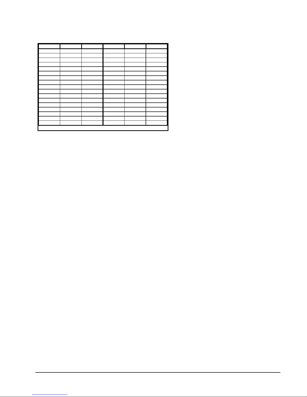
Step Function Dwell (sec) Step Function Dwell (sec)
1
2
3
4
5
6
7
8
9
10
11
12
13
14
15
16
17
n/a (not applicable) means that the dwell time is the time it takes for the function to finish
Pan Right 4
Pan Left 4
Pan Off 4
Tilt Up 4
Tilt Down 4
Tilt Off 4
Zoom In 2
Zoom Out 2
Zoom Off 2
Focus Far 2
Focus Near 2
Focus Off 2
Iris Open 3
Iris Close 3
Iris Off 2
Autofocus n/a
Autoiris n/a
Table 5
Diagnostic Functions Routine
18
19
20
21
22
23
24
25
26
27
28
29
30
31
32
33
Aux 1 ON 2
Aux 2 ON 2
Aux 3 ON 2
Aux 4 ON 2
Aux 5 ON 2
Aux 6 ON 2
Aux 7 ON 2
Aux 8 ON 2
Aux 1 OFF n/a
Aux 2 OFF n/a
Aux 3 OFF n/a
Aux 4 OFF n/a
Aux 5 OFF n/a
Aux 6 OFF n/a
Aux 7 OFF n/a
Aux 8 OFF n/a
Running the Diagnostic Test
The diagnostic test was designed to cycle the
Mini Dome through all its functions. A cycle
consists of a specific series of steps which are
initiated for predefined dwell periods. Each
step is displayed on the viewing monitor.
Completion of each step can be confirmed by
simultaneously comparing the monitor prompts
with the actual action of the Mini Dome. The
cycle is repeated indefinitely until operator
intervention occurs. The cycle steps are as
follows:
To run the built-in diagnostic it is necessary to disassemble the dome. Refer to the Section “Disassembling
the Mini Dome” for specific instructions.
1. Set the RUN/SERVICE Switch to the RUN position.
2. Disassemble the Mini Dome.
3. Set switches 1,2 and 3 of DIP Switch 5 (S5) to the ON position.
4. Reinstall the Drive into the Housing. Refer to Section “Installing the Drive Mechanism” to continue.
5. Set the RUN/SERVICE switch to the SERVICE position. The Mini Dome runs its power-up test and
immediately runs the diagnostic test. The diagnostic test continues to loop until the RUN/SERVICE
Switch is set back to the RUN position. See Table 5 for the exact diagnostic routine.
To disable the diagnostic test and return the Mini Dome back to normal operation, place the RUN/SERVICE
switch back to the RUN position, remove the Drive, reset the DIP switches, reinstall the Drive and place the
switch into the SERVICE position.
X971 Rev 1098 Surveyor Mini Dome System Operation • 27

NOTES
28 • Operation X971 Rev 1098 Surveyor Mini Dome System

Maintenance
The Surveyor Mini Dome requires no scheduled maintenance, however the Domes require occasional
cleaning .
CARE AND CLEANING OF METALLIZED DOMES
1. Always handle the Dome by the flange and avoid touching the inside surface as acid in a fingerprint can
etch the coating. Use the recommended cleaning procedure in Step 4.
2. If dust or dirt accumulate in the dome's interior, it should be removed with clean dry pressurized air.
3. If spots, streaks or stains appear on the inner Dome, they can be removed by rinsing with clean water
and drying with clean, dry pressurized air. Do not rub the inner surface.
CAUTION: Rubbing on the inner Dome surface can cause permanent scratches
4. If wiping is necessary, use a wick. Make a "wick" by rolling a section of soft paper towel into a tightly
wound tube and tear it in half. Moisten the torn edge of the wick with a solution of mild soap and water.
Hold the Dome upside down and gently wipe the surface from the inside to the outer edge. Then, rinse
with clean water and dry with clean, dry pressurized air.
5. Clean the Dome's exterior with any soft cleaning cloth and a mild glass cleaner suitable for acrylic plastic.
CARE AND CLEANING OF CLEAR ACRYLIC DOMES
1. Always handle the Dome by the flange and touching the inside surface.
2. If dust or dirt accumulate in the dome's interior, it should be removed with clean dry pressurized air.
3. If spots, streaks or stains appear on the inner Dome, they can be removed with a solution of mild soap or
isopropyl alcohol and water using a lint-free soft paper towel. Dry with clean, dry pressurized air.
4. Scratches or surface blemishes may be removed with a nonabrasive wax using a soft cleaning cloth
CAUTION: Excessive rubbing of the Dome surface can cause permanent scratches.
5. Clean the Dome's surfaces with any soft cleaning cloth and a mild glass cleaner suitable for acrylic
plastic.
Fuse Replacement
Two fuses (F1 and F2) are located on the Customer Interface Board. When necessary, replace them with the
following fuse value:
2AG, 3.5 amp, 250 volt, slo-blo
X971 Rev 1098 Surveyor Mini Dome System Maintenance • 29

NOTES
30 • Maintenance X971 Rev 1098 Surveyor Mini Dome System

Shipping Instructions
Use the following procedure when returning a unit to the factory:
1. Call or write Vicon for a Return Authorization (R.A.) at one of the locations listed below. Record the name
of the Vicon employee who issued the R.A.
Vicon Industries Inc.
89 Arkay Drive
Hauppauge, NY 11788
Phone: 516-952-CCTV (2288); Toll-Free: 1-800-645-9116; Fax: 516-951-CCTV (2288)
For service or returns from countries in Europe, contact:
Vicon Industries (U.K.) Ltd
Brunel Way
Fareham, PO15 5TX
United Kingdom
Phone: 44/(0)1489/566300; Fax: 44/(0)1489/566322
2. Attach a sheet of paper to the unit with the following information:
a. Name and address of the company returning the unit
b. Name of the Vicon employee who issued the R.A.
c. R. A. number
d. Brief description of the installation
e. Complete description of the problem and circumstances under which it occurs
f. Unit’s original date of purchase, if still under warranty
3. Pack the unit carefully. Use the original shipping carton or its equivalent for maximum protection.
Mark the R.A. number on the outside of the carton on the shipping label.
X971 Rev 1098 Surveyor Mini Dome System Shipping Instructions • 31

NOTES
32 • Shipping Instructions X971 Rev 1098 Surveyor Mini Dome System

Reference
Coaxial Cable
CAUTION: Careful selection of the proper cable is essential to obtain the best performance from this
equipment. Vicon assumes no responsibility for poor performance when cables other than
those recommended are installed. In all cases, coaxial cable impedance should be 75 ohms.
Materials
Use only cable with a pure copper center conductor. Do not use cable with either a copper-plated steel or an aluminum
center conductor because these do not transfer signals effectively in the frequency range used in CCTV networks. A
center conductor with low DC resistance is required for effective CCTV operation. Solid-core bare copper conductor is
best suited to video applications, except where flexing occurs. If the coaxial cable will be subjected to flexing during
normal use, select a cable with a stranded center conductor. The preferred dielectric material is cellular (foam)
polyethylene. It has better electrical characteristics than solid polyethylene, but is more vulnerable to moisture. Therefore,
use only solid polyethylene dielectric cable with a heavy exterior insulation in applications subject to moisture.
Cable Types
The most commonly used cable types are RG-59/U and RG-11/U. Each is actually a family of cables with widely varying
electrical characteristics, some of which are not suitable for CCTV applications.
Choose a cable type by referring to the characteristics and maximum distances listed below. The maximum distance for
best picture refers to the distance between the receiver and the transmitter. The characteristics of the cables in this table
should be used as a guideline when cables other then Belden are used. Materials and construction must follow the
guidelines above. Note that “BC” refers to bare copper and “TC” refers to tinned copper.
Amplification
When Vicoax systems are used with bidirectional amplification a significant increase in the usable cable distance is shown
in the last column of this table. The V1921BDA Bidirectional Amplifier may only be used with the “standard Vicoax mode”.
This amplifier will not work when the Surveyor is in V1422 mode.
Table 6
Recommended Coaxial Cable Types
Cable
Type
RG-11/U 8213 9847 811,4811 14 Solid BC BC braid (95%) 2.6 (8.5) 820 (250) 5000 (1500)
RG-6/U 9248 9804C 806,4806 18 Solid BC Foil + 61% TC
RG-59/U 8281 9803 815 20 Solid BC 2 TC braids (96%) 9.9 (32.5) 400 (120) 5000 (1500)
RG-59/U 9259 ---- 816 22 Strand BC BC braid (95%) 15.0 (49) 400 (120) 5000 (1500)
RG-59/U 9659 ---- ---- 22 Strand BC BC braid (95%) 15.0 (49) 400 (120) 5000 (1500)
Belden
Type No.
Alpha
Type
No.
West Penn
Type No.
Type Center
Conductor
Type Shield and
% Coverage
braid (100%)
DCR/
1000 ft
(km)
7.5 (24.6) 530 (160) 5000 (1500)
Distance
(max)
ft (m)
Distance
with Amplifier
(max) ft (m)
X971 Rev 1098 Surveyor Mini Dome System Reference • 33

Twisted-Pair Cable
(
)
CAUTION: Careful selection of the proper cable is essential to obtain the best performance from this
equipment. Vicon assumes no responsibility for poor performance when cables other than
those recommended are installed.
Materials
Use a pure copper stranded conductor with or without a tin plating to obtain a low DC resistance. Do not use cable with
either a steel or an aluminum stranded conductor because these do not transfer signals effectively for long distances. The
preferred insulation and cable jacket is Polyvinyl chloride (PVC). It has better electrical characteristics than polyethylene
and resists flames, sunlight and most solvents, but is more vulnerable to moisture.
Cable Types
The most commonly used cable types are dual individually-shielded, twisted-pair in a single jacket. This configuration is
the most convenient for RS-422/ RS485 applications. Single twisted-pair is also a suitable cable.
Choose a Belden cable type by referring to the characteristics and maximum distances listed below. The maximum
distance for the most reliable digital control refers to the distance between the CPU/ Keypad and the Dome. The
characteristics of the cables in this table should be used as a guideline when cables other then Belden are used. Materials
and construction must follow the guidelines above.
Table 7
Recommended I
ndividually-Shielded, Twisted-Pair Cable Types
CABLE
TYPE
Belden 9406
Belden 9402
Belden 8723
Belden 8162
Belden 9729
Belden 9182
¹
Datalene is a Registered Trademark of Belden.
WIRE SIZE
AWG
22 PVC PVC 5000 (1500)
20 PVC PVC 5000 (1500)
22 Polypropylene PVC 8000 (2400)
24 Datalene¹ PVC 15000 (4600)
24 Datalene¹ PVC 15000 (4600)
22 Datalene¹ PVC 25000 (7600)
INSULATION
MATERIAL
JACKET
MATERIAL
DISTANCE ft (m)
max.
1.5-inch Pipe Designation
The standard “1.5-inch pipe” referred to in this manual actual dimensions:
External diameter: 1.900 inches (4.83 cm).
Wall thickness: 0.145 inches (0.368 cm) minimum (ANSI “standard” grade thickness).
NUMBER OF
TWISTED PAIRS
2
2
2
2
2
1
34 • Reference X971 Rev 1098 Surveyor Mini Dome System

Technical Information
ELECTRICAL
Drive Type: V7UVS-RPX2. See Table 9.
Housing Types: Units available for indoor or outdoor operation. See Table 9.
Camera Types: Units available in monochrome (EIA, CCIR) or color (NTSC,
PAL).
Input Voltage: 24 VAC nominal ±10% maximum. Class 2 indoor/dry or
Class 3 outdoor/wet.
26.4 VAC maximum
21.6 VAC minimum
Wire Size for Specified Cable Run Lengths: see Table 8.
Wire Size (AWG)
(Annealed Copper Wire)
20
18
16
14
12
Current Drain: Indoor: 1.89 amps.
Outdoor: 3.30 amps (Heater/Blower included).
Power Consumption: Indoor: 47.6 watts maximum.
Heat Equivalent: Indoor: 2.7 btu/min (0.7 cal/min).
Outdoor: 4.7 btu/min (1.2 cal/min).
Indoor, ft (m)
(without Heater and Blower)
60 (18) 25 (8)
100 (30) 40 (12)
150 (46) 60 (18)
250 (76) 100 (30)
400 (122) 165 (50)
Table 8
Applicable Wire Size
Outdoor: 83.2 watts maximum (Heater/Blower included).
Outdoor, ft (m)
(with Heater and Blower)
Note: These figures represent the conversion of 100% of the electrical energy to heat. Actual percentage of
the heat generated will be less and will vary from product to product. These figures are provided as an
aid in determining the extent of cooling required for an installation.
Video Output Impedance: 75 ohms.
Fuse: F1: 2AG, 3.5 amp 250 VAC, slo-blo.
F1: 2AG, 3.5 amp 250 VAC, slo-blo.
Radio Frequency Emission Rating: FCC Class A.
X971 Rev 1098 Surveyor Mini Dome System Technical Information • 35

European Community
(CE) Standards: EN 50081-1 generic emissions.
EN-50082-1 generic immunity.
Safety Standard: UL1409.
CONTROLS & CONNECTORS
Connectors: Video: BNC-F.
Power: Screw terminal block, 3 position.
Control Input/Output: Removable screw terminal block, 12
position.
Relay Output: Removable screw terminal block, 12 position.
Alarm Input: Removable screw terminal block, 12 position.
Service Switch: Two position toggle switch, located at the base of unit,
having positions RUN and SERVICE. RUN enables normal
operation with the Mask installed and SERVICE enables
normal operation with the Mask removed.
Tamper Indicator: Red LED, located at the base of unit, illuminates when the
Mask is removed (renders unit inoperable).
Service Indicator: Green LED, located at the base of unit, illuminates when the
Service Switch is set to the Service position.
OPERATIONAL
Pan Speed: Variable, 1 - 370°/ sec.
Tilt Speed: Variable, 1 - 120°/ sec.
Preset Capabilities: 79 individual programmable preset positions.
Tour Capabilities: 10 tours available with 32 programmable events per tour.
Events may be preset positions, alarm acknowledgement,
alarm or preset dwell times, auxiliary function activation, tour
repeat or chaining tours.
Preset Solving Speed: 1 second maximum.
Preset Repeatability: 0.3° maximum.
36 • Technical Information X971 Rev 1098 Surveyor Mini Dome System

Alarm Capabilities: 8 individual input screw terminal connections.
Individual input enable/disable.
Alarm report to CPU enable/disable.
Active level definition (high/low).
Alarm acknowledge definition (manual or automatic) with
programmable dwell time.
Alarm action definition (preset solve, aux on/off, tour or no
action).
Alarm titling.
Auxiliary Capabilities: 8 individual output screw terminal connections.
Active level definition (high/low).
Individual power-on state definition (on/off).
Output type definition (momentary or latching).
Auxiliary function status titling.
Control Hardware: Vicon’s NOVA, V1902VCT, V1422 control transmitters,
desktop keypad V1300X-DVC or rack-mounted keypad
V1300X-RVC.
Control Software: Vicon’s ProTech software (or compatible) run on a
standard PC type computer with an RS-422 half duplex
protocol interface.
Control Format: RS-422 data, simplex or half duplex operation at 4800 or
9600 baud; switch selectable (factory set to 4800 baud).
Control Display: On-screen, menu-driven system allowing full configuration of
the Mini Dome.
Screen Titling Capabilities: Programmable for Camera, Preset, Sector and Alarms.
Fixed for Auxiliary Function and Lens status.
(Camera: 1 for each).
(Preset: 79 maximum).
(Sector: 16 maximum).
(Alarm: 8 maximum).
Individual type enable/disable.
24 characters maximum.
Selectable position.
MECHANICAL
Application: Indoor or outdoor.
Mounting: In-ceiling or pendant (kits provided).
Pendant Mount Size/Thread: Standard 1.5-inch NPT pipe thread or metric equivalent.
Lower Fixed Dome Types: Units available for in-ceiling or pendant mount and in a
variety of colors. See Table 9.
Dimensions: See Table 10.
X971 Rev 1098 Surveyor Mini Dome System Technical Information • 37

Weight: 12.0 lb (5.4 kg), basic unit.
Construction: Plastic, aluminum and steel.
Finish: Matte light beige Housing.
ENVIRONMENTAL
Operating Temperature Range: Indoor: 35 to 120°F (2 to 49°C).
Outdoor: -30 to 130°F (-35 to 55°C).
Operating Humidity Range: Indoor: up to 90% relative, noncondensing.
Outdoor: 100% relative.
Storage Temperature Range: -40° to 150° F (-40° to 65° C).
Storage Humidity Range: Up to 90% relative, noncondensing.
Wind Load: Outdoor: Heavy rain or snow driven by winds up to 80 mph.
MODEL NUMBER
V7UVS-RPX2
V7USD-V2
V7USD-W-VS
V7ULD-SI
V7ULD-CI
V7ULD-GI
V7ULD-SP
V7ULD-CP
V7ULD-GP
MODEL NUMBER
V7USD-V2
V7USD-W-VS
V7UFR (Shield)
PRODUCT CODE DESCRIPTION
5992
6108
4981
6085
6086
6087
6088
6089
6090
Drive Mechanism
, indoor version, ceiling or pendant mount, lower dome sold separately.
Housing
, outdoor version, pendant mount with Sunshield, Lower Outdoor Dome included.
Housing
Lower Dome
Lower Dome
Lower Dome
Lower Dome
Lower Dome
Lower Dome
, variable speed with pan and tilt. Inboard communications, fully programmable.
, indoor, ceiling mount, gray tint (smoked).
, indoor, ceiling mount, chrome.
, indoor, ceiling mount, gold.
, indoor, pendant mount, gray tint (smoked).
, indoor, pendant mount, chrom e.
, indoor, pendant mount, gold.
Table 9
Surveyor Components
HOUSING DIAMETER
in. (cm)
12.0 (30.5)
14.3 (36.3)
12.4 (31.5)
DOME DIAMETER
in. (cm)
7.75 (19.7)
11.3 (28.7)
7.75 (19.7)
HOUSING HEIGHT
in. (cm)
8.6 (21.8) 12.2 (31.0)
8.7 (22.1) 13.3 (33.8)
9.1 (23.1) 12.5 (31.8)
Table 10
Surveyor Overall Dimensions
TOTAL HEIGHT
in. (cm)
38 • Technical Information X971 Rev 1098 Surveyor Mini Dome System

NOTES
X971 Rev 1098 Surveyor Mini Dome System Technical Information • 39
 Loading...