

Page 1
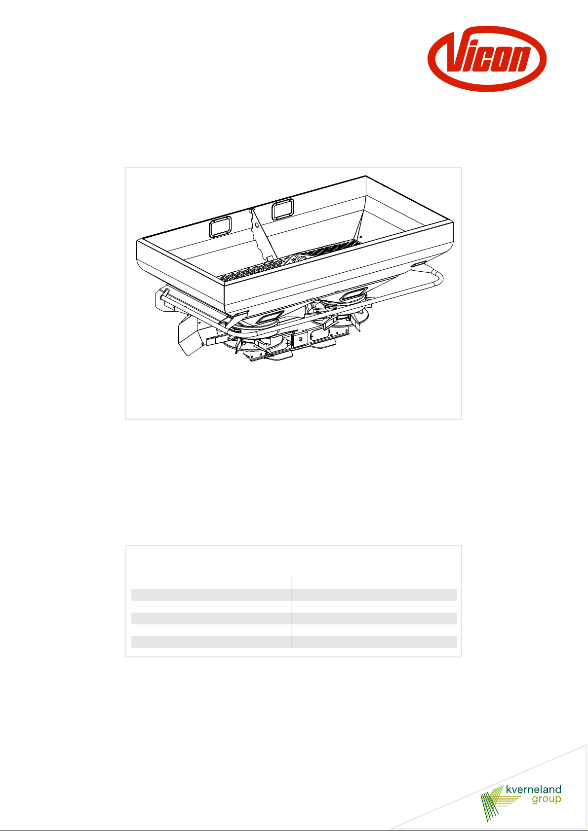
RO-M EW
User Manual
Item 01-2015
Print date 02.2015
Language EN
From software version V 1.11
Serial number From VN251
Reference number A138039240-1
Page 2

Machine identification
In order to provide you with good service various details about your machine may sometimes be required.
Please complete these details here in order to have them at hand when they are requested.
Type of machine
Serial number
Options
Address
dealer
RO-M EW
Address
manufacturer
Kverneland Group Nieuw-Vennep B.V holds all copyrights and rights of use. The contents of this user manual can be modified without prior
notification. All rights reserved. Th e holder reserves the right of technical modific ations.
Kverneland Group Nieuw-Vennep B.V.
Hoofdweg 1278
NL-2153 LR Nieuw-Vennep
The Netherlands
Page 3

Table of contents
Preface ....................................................... 4
Target group of this manual 4
Meaning of symbols 5
Safety ......................................................... 6
For your safety 6
Other guidelines 6
Warning stickers 7
Safety regulations 10
Getting familiar with the machine ........... 24
Applications of the machine 24
RotaFlow spreading system 24
Adjust carefully 24
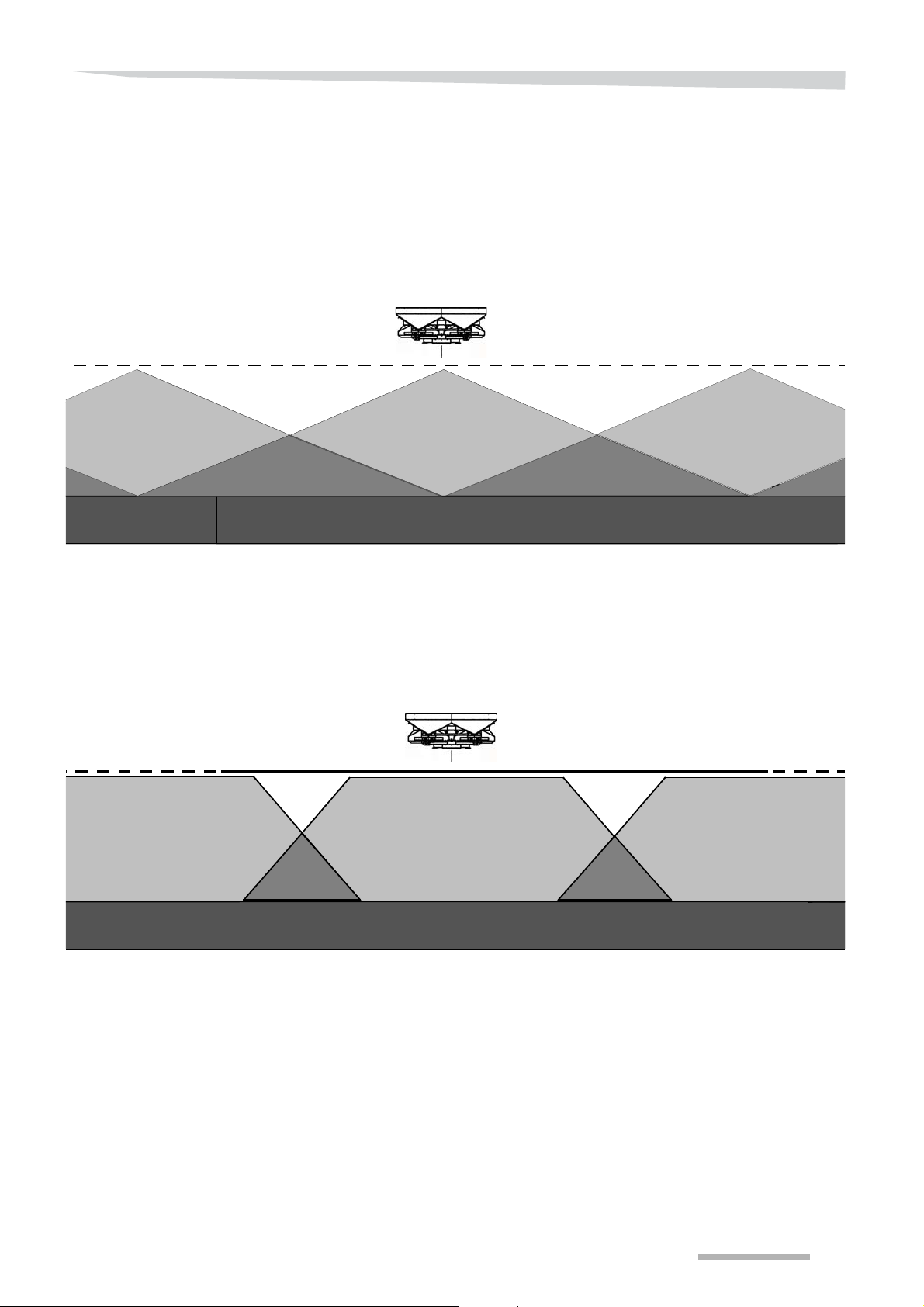
Spreading patterns 27
The ISO control system 30
Technical specifications 44
Before first use ......................................... 46
Inspect the supplied machine 46
Mounting instructions 46
Tractor provisions 63
Mounting the coupling shaft 64
Connecting to the tractor ......................... 68
Selecting linkage pin height 69
Connecting the machine 70
System settings ........................................ 75
Differences in operation 75
Entering system settings 75
Settings behind pin code 83
Settings screen (3) 83
Spreader calibration 92
Alarms 95
Service information 97
Activities before spreading ..................... 100
Find the correct settings for setting the
spreader 100
Spreader setting 105
Working width 108
Inclination 111
PTO shaft rpm 111
Application rate 112
Manual calibration test 123
Variable, externally driven application
rate 126
Filling 128
Spreading pattern check (tray test) 131
Table of contents
Spreading 159
Border spreading 165
Stopping work 171
Failure and stoppage 172
Storing the machine .................................. 176
Cleaning 177
Disconnecting the machine 178
Maintenance ............................................... 181
Maintenance intervals 183
Oil and grease content 184
Lubricating points 184
Gearboxes 185
Connectors 185
Torques 186
Checking the hydraulic system 187
Check the settings of the dosing
mechanism 189
Checking and setting the discharge point
setting mechanism 192
Checking and setting the discharge
bushing height 194
Replacing agitator axle seal 196
Setting the weighing sensor 198
Accessories ............................................... 200
Troubleshooting ........................................ 211
Troubleshooting table 211
Decommissioning ..................................... 214
Liability ....................................................... 215
Liability 215
Complaints 216
Guarantee 216
EC declaration of conformity ................... 217
Notes .......................................................... 218
Index ........................................................... 220
Driving on the road ................................... 148
Before taking to the road 148
Preparing the machine to be transported 149
Use in the field .......................................... 150
Adjusting the machine 151
Clearly define tramlines 156
3
Page 4

Preface
Preface
Target group of this
manual
This manual is intended for professional agrarians and other people
trained in working in the field of agriculture, who are competent to
operate this machine, as required by national legislation, and who
have knowledge of assembly activities.
For your safety
Ensure that you are familiar with the contents of this manual before
you start using or assembling the implement. This will ensure that you
obtain an optimum result and are working safely.
See section »Safety regulations« on page 10.
Should you have any questions or if anything is unclear, please
contact the manufacturer.
Ensure that this manual is available to all persons who will be working
with this machine. In this way, you will:
• prevent accidents,
• respect the warranty conditions,
• always have a machine in perfect working order.
For the employer
• All personnel who operate this machine must be authorised to do
so according to the applicable national legislation.
• All personnel are to be trained in the use of the machine regu larl y
(at least once a year) in accordance with employers’ liability
insurance association guidelines. Untrained or unauthorised
individuals are not permitted to use the machinery.
• You are responsible for the safe operation and maintenance of
your machine. You must ensure that you and anyone else who is
going to operate, maintain or work around the unit be familiar with
the operating and maintenance pr oc ed u re s and re la ted safety
instructions as mentioned in this manual.
• You are responsible for providing personal protective gear to
personnel who use the machine or who are performing
maintenance or repairs on it. This includes: safety goggles, safety
shoes, safety gloves, etc.
4
Page 5
Preface
Meaning of symbols
I
NDICATION
V arious symbols are used to provide a clear unde rstanding of the text.
These are explained below:
• A dot is placed before lists.
A triangle marks tasks you have to perform.
An arrow refers to a different place in the text.
In addition, we use pictograms to help you easily find certain text
sections.
The words “Tip“ and “Instruction” are followed by tips or hints for
operation.
The warning triangle indicates important safety regulations. Failing to
comply with these may result in:
• serious operating malfunctions of the machine;
• damage the machine;
• injuries or accidents.
The spanner indicates tips for assembly or adjustment work.
A star indicates that examples will follow that are intended to clarify the
text.
All directional rotations are to be interpreted when facing in direction
of travel.
5
Page 6
Safety
Safety
For your safety
In this chapter, you will find general safety instructions. You will find
more specific safety instructions not described here in every chapter.
Do not risk injury or death by ignoring the safety instructions.
Working with agricultural machines may be dangerous. Prevent
accidents! Do not take undue risks! Be alert at all times!
Think safety! Work in safety!
Disregarding safety instructions, inadeq uat e ma inte nanc e, u se of the
machine for purposes other than for what it is intended, overload ing of
or unauthorised modification to the machine, renders the resultant
manufacturer's warranty and liability void.
Familiarise yourself with the operating functions and safety instructions prior to using the machine.
Incorrect use of the machine may result in dangerous situations. For
this reason, you should always work carefully and never under huge
time pressure.
Other guidelines
Comply with the rules
In addition to the instructions above, you should comply with the
following:
• measures to prevent accidents,
• generally applicable safety instructions, occupational health
requirements and road traffic regulations,
• instructions in this manual,
• rules regarding use, maintenance and repairs.
6
Page 7
Safety
Warning stickers
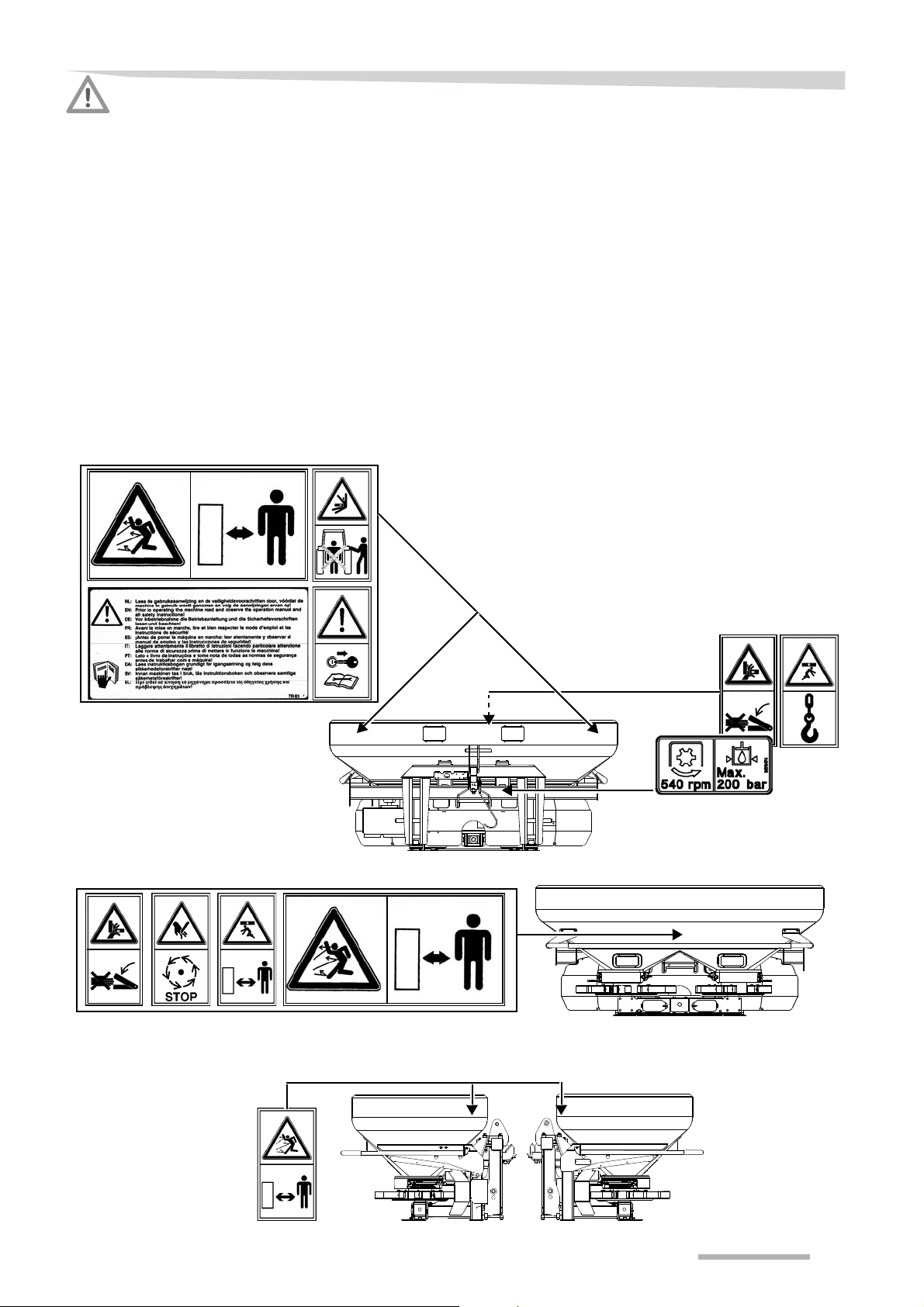
Various warning stickers have been affixed to the machine for safety
reasons. Do not remove them! Always follow the instructions provided
and be alert to possible risks.
Always keep the warning stickers and symbols clean and clearly
legible. Replace warning stickers that are missing, damaged or those
that have become illegible. If original parts on which a warning sticker
or symbol was fixed are replaced, ensure that the replacemen t p art is
also provided with a corresponding warning sticker.
7
Page 8
Safety
Explanation for warning
stickers
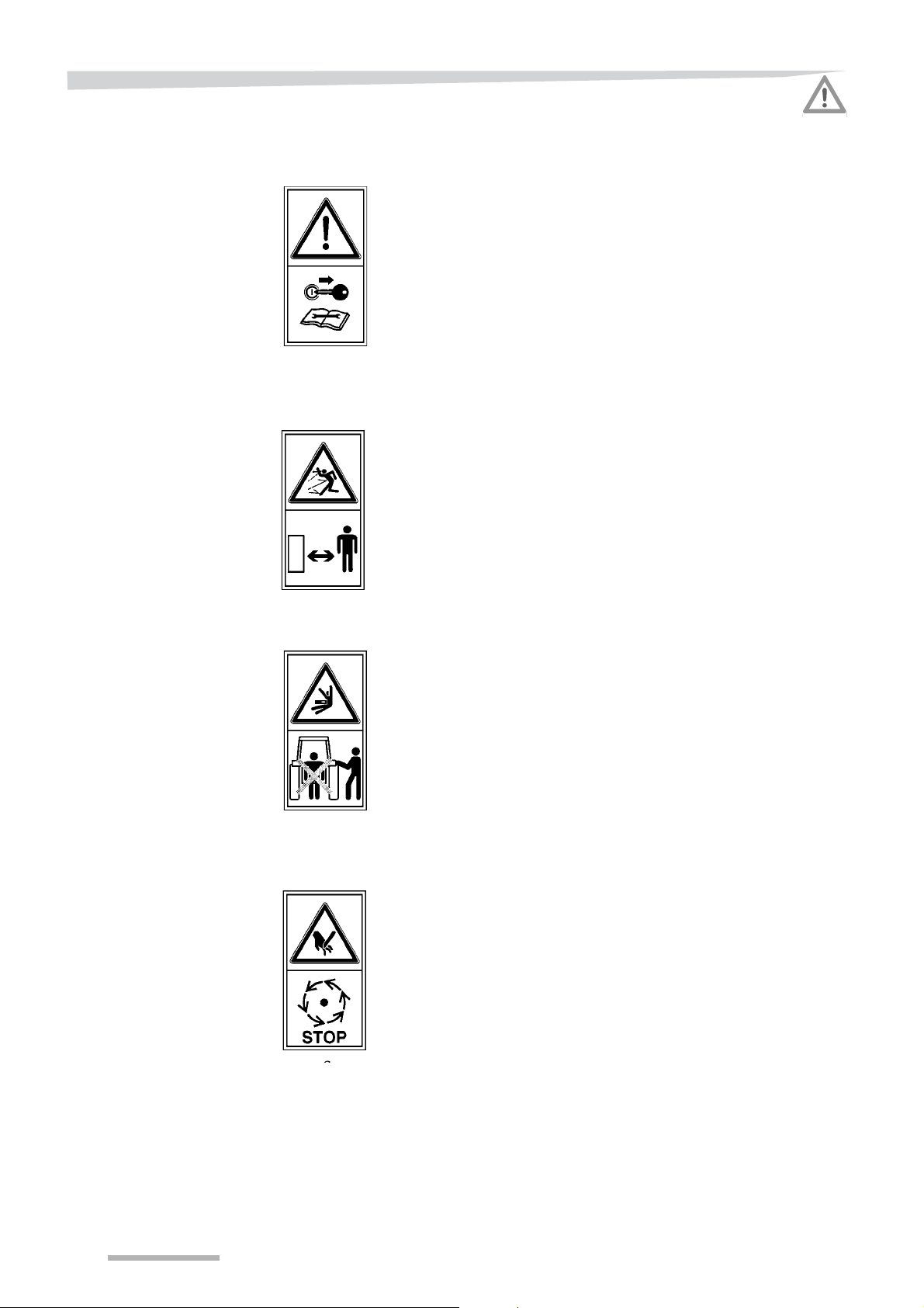
Stop the engine and remove the keys from the ignition
Switch the engine off as soon as you leave the tractor. Remove the
key from the ignition to prevent the tractor from starting up (unintentionally) while you are in the danger zone. This especially applies
when changing the settings or while maintenance and repairs are
being carried out.
Maintain a safe distance from a running machin e
Fertiliser is spread over a great distance during operation. Ensure that
nobody comes within operating range of the machine when it is
running. Do not come into the working area before all parts of the
machine come to a halt.
Operate the power lift only outside the danger zone
There is a danger of being pinned down by the power lift in the area
between the tractor and the machine. Operate the power lif t only from
outside the danger zone for this reason. Secure the tr actor against
rolling away with the handbrake and wheel chocks.
Do not approach the machine until it has come to a complete
standstill
The rotating parts of the machine never come to an immediate halt,
they always wind down. The moving parts of a machine are not always
visible. Do not approach the machine until all moving part s have come
to a complete halt.
8
Page 9
Safety
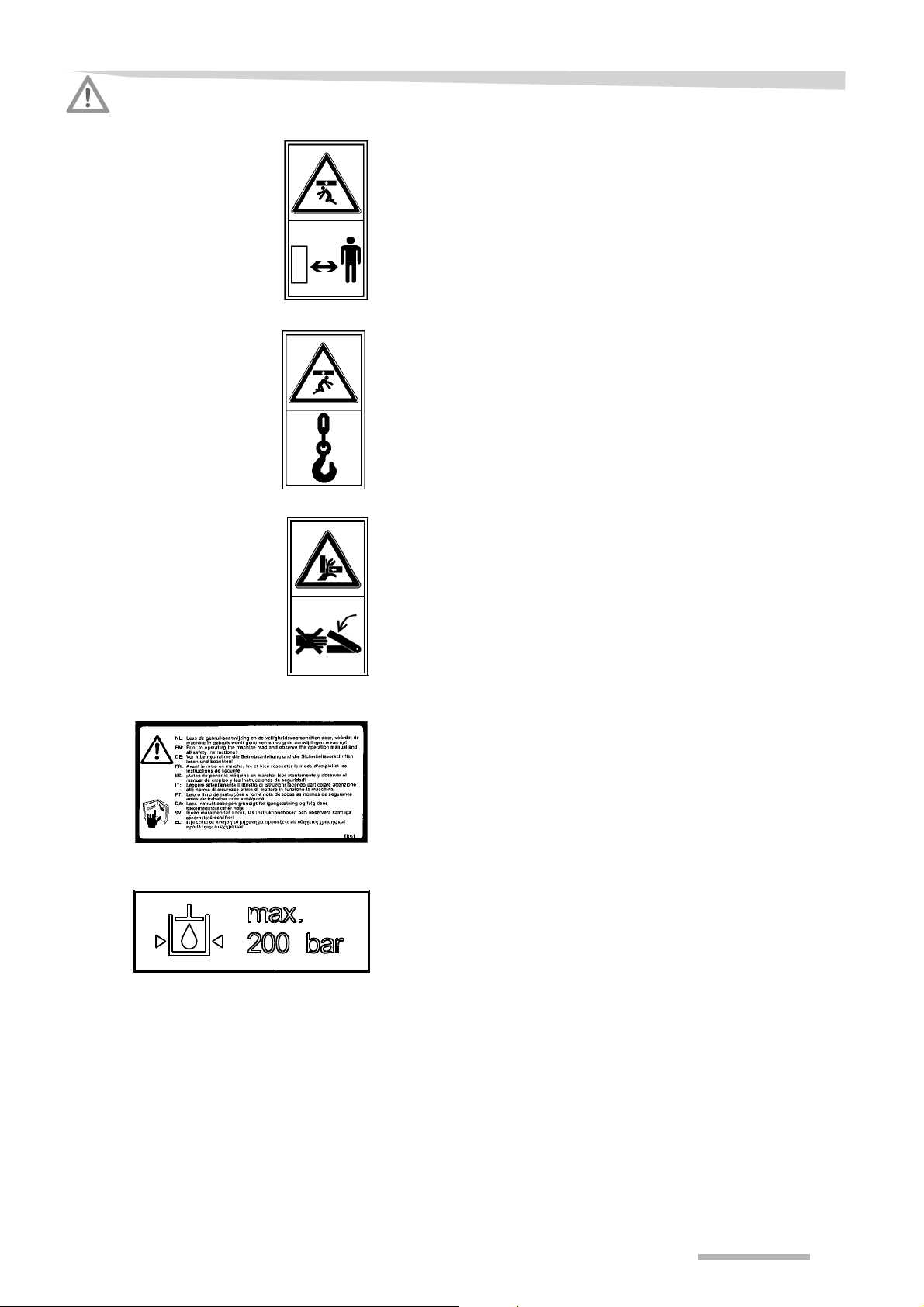
Never go below an elevated, unsecured machine
The machine or parts of the machine could accidentally fall due to
dropping oil pressure, for instance. Always place the machine on
proper supports if you have to work under the machine!
Only lift the machine at the lifting points
If a machine is being elevated, attach it only at the indicated lifting
points. Never go below an elevated machine. Allow for any possible
movements of the elevated machine, whether wanted or not.
Be careful of getting jammed or pinched
If the machine is engaged or operated intentionally or unintentionally,
you could get crushed in moving parts, which could lead to injury. Be
very alert when working in the vicinity of moving part s. Always bear in
mind that the motor or parts of the machine may have some residual
energy.
Read the user’s manual
The instruction manual contains procedures for working correctly to
ensure safe work, as well as dangers one could possibly encounter.
Comply with these procedures as descr ibed and give due consideration to the safety measures in place!
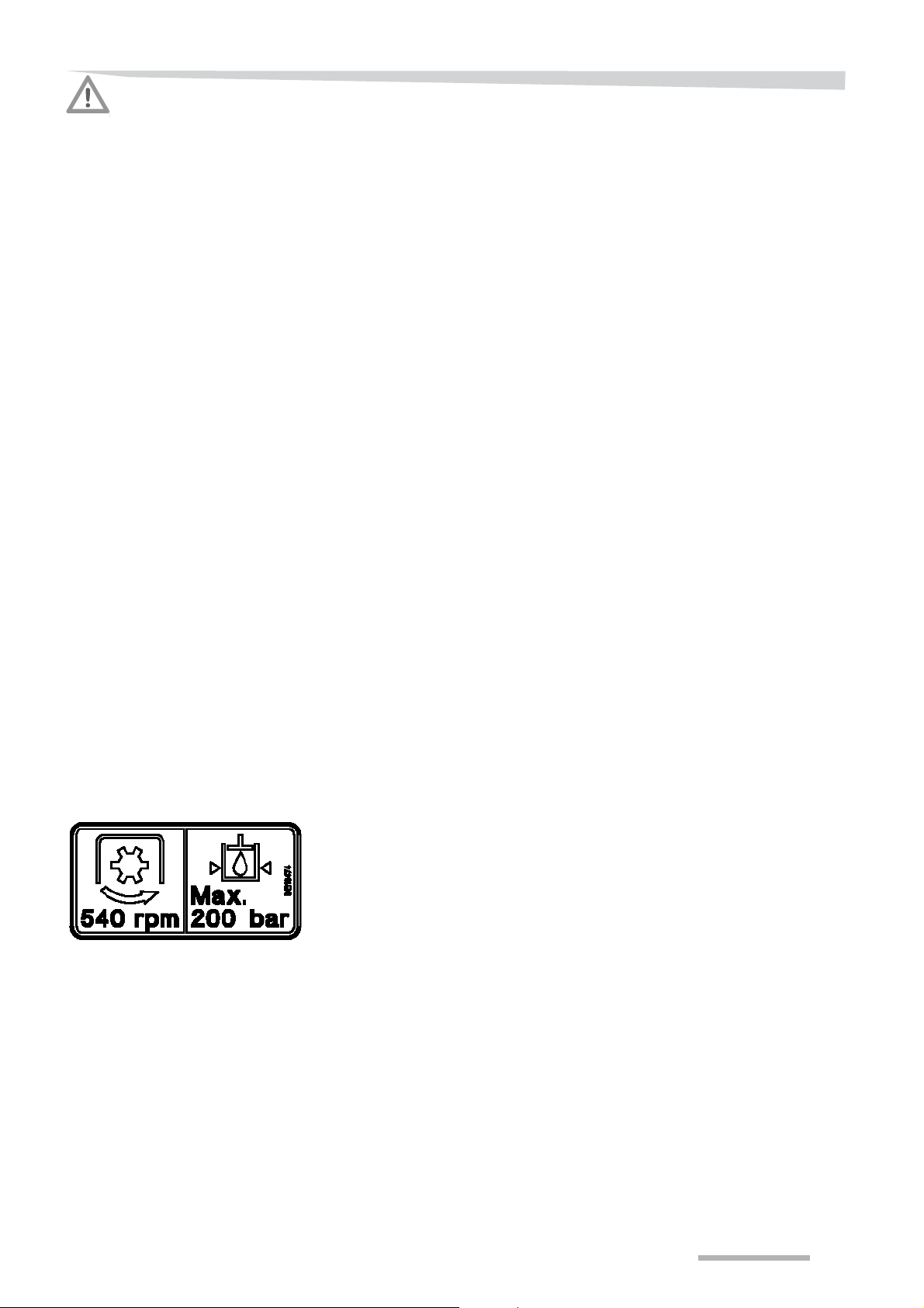
Do not exceed the maximum hydraulic pressure of 200 bars
Prevent the pressure in the hydraulic system from exceeding 200
bars! Working with higher pressure may damag e your machine and
result in dangerous situations.
9
Page 10

Safety
Safety regulations
Intended use
Person
This part contains all the requirements, prohibitions and regulations
that need to be considered for every type of usage, maintenance and
repair of the machine.
The chapters in this user's manual contain additional safety
measures.
Knowledge of the safety regulations forms the basis for safe and
trouble-free usage of the machine.
Always follow the safety instructions. most accidents can be
prevented. Do not run the risk of serious or fatal accidents by
neglecting these safety instructions.
This machine is exclusively intended to spread granular products,
specifically fertiliser types and seeds.
Any other application is considered inappropriate. The manufacturer
is not liable for damage that may result from such usage; risks are
taken exclusively by the user.
The instructions, maintenance requirements and reparation stipulations as indicated by the manufacturer must be adhered to at all times.
Responsibility of the user
The user may only work on or at the machine if he/she:
• is familiar with the basic safety requirements and the working
condition requirements,
• is familiar with current traffic regulations,
• has been duly instructed on how to work on/with the machine and
the related dangers,
• has read and understood this manual,
• is familiar with all the systems and operating elements and their
functions,
• is familiar with the regulations for using, maintaining and r epairing
machines.
It is too late to familiarise oneself with the machine while working!
Irresponsible usage could cause injury to the user or third parties and
damage the machine.
10
Page 11

Safety
Authorisation
Clothes/protection
Only to be used by an authorised person
The machine may be used by authorised people only. A person is
authorised if he/she:
• received training as required by the national authorities,
• has taken responsibility as described in
section »Person« on page 10.
Maintenance and repairs by experts
Maintenance, replacement of parts and repairs to the machine may
only be performed by experts.
A person is considered to be an expert if he/she has sufficient
knowledge in the fields of safety , maintenance, production and r epairs
as a result of training and experience.
Maintenance or repairs performed by an unskilled person could lead
to injury and damage the machine.
Wear close-fitting clothing
Avoid wearing loose fitting clothing. Loose clothing could become
entangled with moving parts, which could cause serious or fatal
injuries.
Ensure personal protection
Ensure your personal protection. Wear:
• safety goggles,
• safety shoes,
• safety gloves.
Prevent hearing damage
Your hearing could be damaged when working with the tractor and
machine with noise levels in excess of 80 dB. Use the appropriate ea r
protection in order to prevent hearing damage. Remaining in an area
with high noise levels for extended periods of time could seriously
damage your hearing.
What to do in the event of injury
In the event of injury and if you suspect that you made contact with
materials you should:
• clean the point of contact with a lot of water,
• contact your physician immediately!
11
Page 12

Safety
Workplace
Tractor
To be used and operated by 1 person
The machine may only be operated by one person, from the tractor.
Operating the machine from the tractor will keep you out of harm's
way.
Other people should not be in the direct vicinity of the machine and the
tractor. Those who are within the working area and the danger zone
could be injured.
Check the immediate surroundings
Check the immediate surroundings and keep a constant eye on them
when starting and while operating with and at the machine. Familiarise
yourself with the immediate surroundings. Do not start working until all
people and obstacles within the working area and danger zone of the
tractor and machine have been removed.
Never stay or allow anyone to stay within the danger area while the
machine is running! If there are people within the wor king area and the
danger zone it could lead to injury.
Check the condition of the tractor and machine
Only work with a correctly working tractor and machine.
Always check that:
• all lights, safety and warning provisions must be mounted correctly
and be in good working condition,
• the lifting and pulling capabilities must be sufficient,
see »Calculate the axle load with tractor-mounted machines«
on page 14,
• the tractor must be suitable for the machine, such as in the area of
stability, engine capability, axle load and total weight,
• it is sufficient for the working with the machine and for transport.
Comply with maximum permissible axle loads, total weights and
transport dimensions! Using an unsuitable tractor may cause serious
or lethal injuries or damage the machine.
See the tractor’s technical details.
12
Page 13

Safety
Put a fire extinguisher in place
Carry a fire extinguisher at all time s, especially when operating with
flammable materials. This should be a multi-purpose ABC rated fire
extinguisher with a 5 kg capacity, approved by the appropriate
authority. Mount this onto the tractor and/or onto the machine. Fire
could damage the machine and cause injury.
Use active carbon filters
Harmful gases and mists could enter the air duct of the tractor while it
is in use.
An active carbon filter should therefore be mounted in the air
ventilation of the tractor.
Harmful materials could cause serious personal injury.
Ensure the tractor is safe when leaving it
Never leave the tractor without:
• switching off the PTO shaft,
• switching off the electric control system,
• releasing the pressure from the hydraulic system,
• switching off the tractor engine,
• removing the key from the ignition,
• engaging the handbrake of the tractor.
Leaving the tractor unsecured could create dangerous situations that
could lead to injury.
Responding to problems
In the event of operational problems you should:
• stop immediately,
• switch the tractor and machine off,
• attend to the problem or call for expert assistance.
Never use the tractor in a closed area
The tractor must never be used in a closed area. Exhaust fumes may
accumulate without being noticed. Exhaust fumes may cause serious
or lethal injuries.
13
Page 14

Safety
Calculate the axle load with
tractor-mounted machines
The following are important to ensure safe operation of the loaded
machine :
• the maximum load of the machine,
• the maximum axle load of the tractor,
• weight distribution over the axles,
• and the carry load per wheel.
At least 20% of the tractor's own weight must rest on the front axle and
45% on the rear axle in the loaded condition in order to maintain good
manoeuvrability.
Check that these conditions are satisfied before purchasing a
machine! Comply with maximum permissible axle loads, total weights
and transport dimensions! Using a tractor which is not proper may
cause serious or lethal injuries or damage the tractor and machine.
14
Page 15
Safety
D
B
C
A
E
i
hgf
Required details
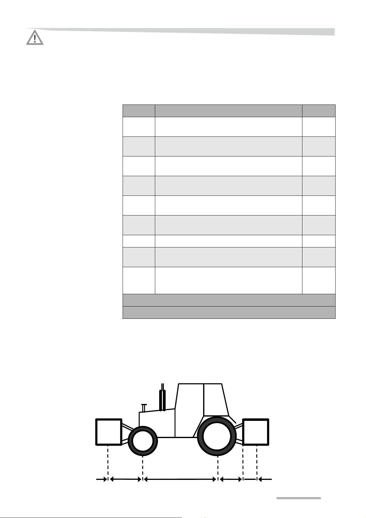
The following details are necessary in order to calculate the minimum
requirements and actual axle load, as well as the actual and maximum
total weight. You will find details of the tractor in the tractor manual.
You will find details of the tyres in the information provided by the tyre
manufacturer. The details of the machine are in this manual.
in section »Technical specifications« on page 44.
Letter Description Unit
A The basic weight of the tractor without the machine
(1) being attached
B The weight on the front axle of the tractor without the
machine (1) being attached
C The weight on the rear axle of the tractor without the
machine (1) being attached
D The total weight of the machine or weights attached
at the front end
E The total weight of the machine or weights attached
at the rear end
f The distance between the centre of gravity of the
machine and the middle point of the front axle
Kg
Kg
Kg
Kg
Kg
m
g Wheel base of the tractor m
h The distance between the centre of the rear axle
and the centre point of the lifting arm attachment
i The distance between the centre of gravity of the
machine and the middle of the point of attachment of
the lifting arm (2)
(1) Take account of accessories or the weight of water in the tyres
(2) If unknown, take i = half the machine length
m
m
15
Page 16

Safety
Actual total weight (kg) = A + D + E
g
Actual front axle load =
D x ( f + g ) + ( B + g ) - E x (h + i )
Actual rear axle load (kg) =
actual total weight (kg) -
actual front axle load (kg)
f + g
Front ballast required (kg) =
E x ( h + i ) - ( B + g ) + (0.2 x A x g )
Calculations
The calculations can be made with the values given in the abovementioned chart.
Actual total weight
The actual total weight must not exceed the permitted total weight.
The actual total weight (in kg) is calculated as follows:
Actual front axle load
The actual front axle load must not exceed the permitted maximum
load. The actual total front axle load (in kg) is calculated as follows:
Actual rear axle load
The actual rear axle load must not exceed the permitted maximum
load. The actual total rear axle load (in kg) is calculated as follows:
Ballast required in the front
The minimum load on the front axle must be 20% of the basic weight
of the tractor. With a machine mounted in the power lift behind the
tractor, the minimum required ballast (in kg) in front of the tractor is
calculated as follows:
If the calculated value is negative no additional ballast is required.
16
Page 17
Safety
g + h + i
Rear ballast required (kg) =
( D x f ) - ( C + g ) + (0.45 x A x g )
Ballast required in the rear
The minimum load on the rear axle must be 45% of the basic weight
of the tractor. With a machine mounted in the front power lift, the
minimum required ballast (in kg) in the power lift behind the tractor is
calculated as follows:
If the calculated value is negative no additional ballast is required.
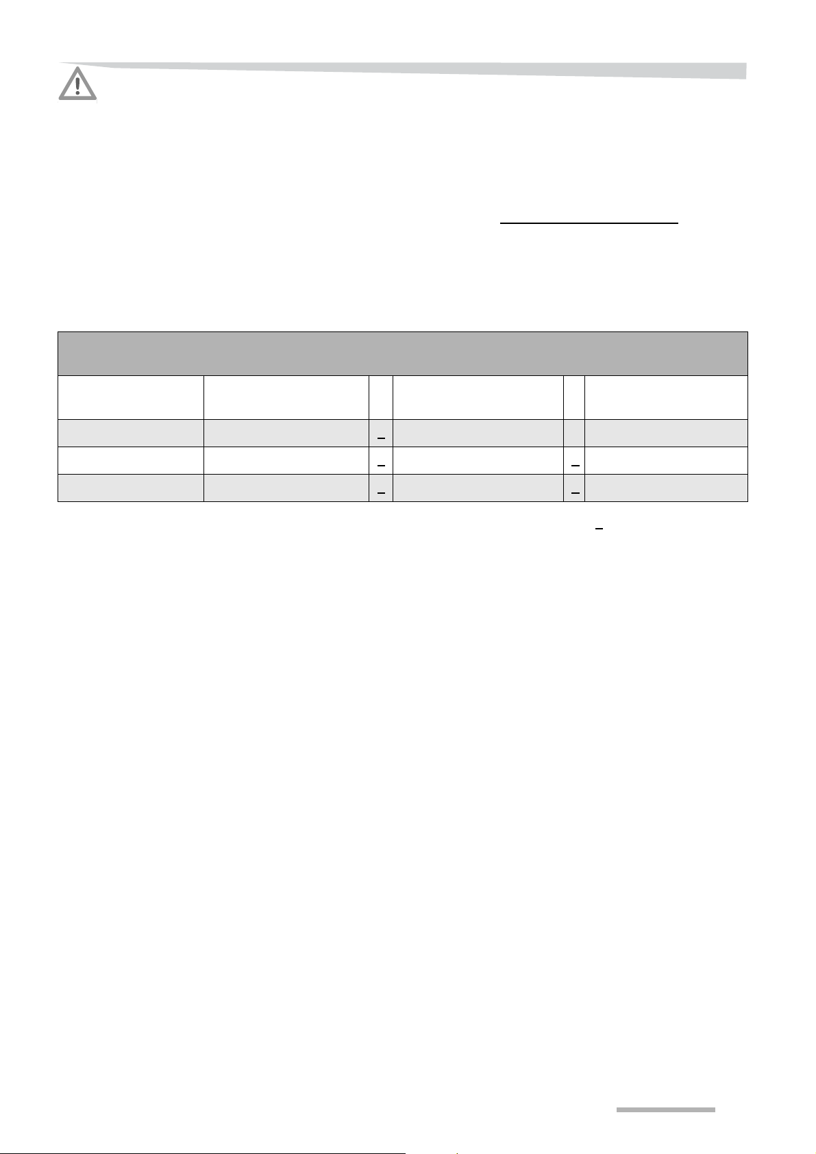
Actual calculated
value
Minimum load on
front/rear axle
Total weight Kg < Kg -Load on front axle Kg <
Load on rear axle Kg < Kg < Kg
/ Kg -- --
The calculated value must be less than ( <
permitted values. The front and re ar loads must be greater than the
minimum load of the front and rear axles respectively.
TIPIf you have access to a weigh bridge with sufficient measuring range,
the total weight and the front and rear axle load can also be
determined by weighing.
Value permitted as per
the manual
Kg < Kg
Load capacity of 2
tyres
) or equal to ( = ) the
17
Page 18

Safety
Machine
Check the condition of the machine before use
Check the following before using the machine:
• is the machine in a good working condition and safe?
• are all lights, safety and warning provisions correctly mounted a nd
in good working condition?
• are the brakes of the machine working properly and have they
been adjusted to the correct position?
Using an unsafe machine could result in personal injury and damage
the machine.
The machine should only carry, not pull!
It is not permitted to use the machine for pulling as this would have
detrimental consequences to its construction. This could lead to
dangerous situations for bystanders, unsafe operation or damage
crops.
Do not stand on the machine
Being on the machine during activities and transport is prohibited. You
may only be present on the parts of the machine intended for the
purpose if it is standing still and prevented from rolling by means of
hand brake and wheel chocks. Being on the machine when in any
other state could lead to serious injury.
Never work on a running machine
Never work on a running machine. A running machine has several
moving parts which cannot be seen. Wait until all parts have come to
a complete halt. Moving parts may cause serious injuries.
Safety stickers
Follow the instructions on the stickers
The safety stickers on the machine give important instruction for risk
free operation. Observe these instructions to ensure your safety.
Replace any missing or illegible safety stickers and signs
When parts with a safety decal or safety sign are rep laced, check that
the replacement part has the safety decal or safety sign intended.
Stickers that are not legible must be replaced so that they are clea rly
legible at all times.
18
Page 19
Safety
Coupling shaft
Use the correct coupling shaft
Only use coupling shafts complying with the manufacturer’s specification for that specific use! In order to ensure pr otection o f both man
and machine exercise extreme caution when performing activities with
or at a coupling shaft other than those described in this manual or on
the instruction provided on the coupling shaft.
Modifications to and other special activities at coupling shaf ts are only
permitted with the explicit written instruction and approval of the
manufacturers of both the machine and the coupling shaft. Use the
correct tools and original parts to ensure good performance and
maximum safety. The use of an incorrect coupling shaft may damage
the machine.
Mount the appropriate protection
Externally accessible coupling shafts, the tractor's PTO shafts and
machine input-axle must be equipped with appropriate guards and
tubes. Working without protection may cause serious or lethal injuries.
Replace protective coupling shaft tubes in a timely manne r
Replace the coupling shaft protection sleeves upon the first sign s of
wear and tear. Protection sleeves may get worn out without being
noticed. Worn or damaged protection sleeves may cause serious or
lethal injuries.
Protect the PTO shaft end well
Slide the protection sleeve over the PTO shaft as soon as the coupling
shaft has been removed. Clothing could get entangled with an
unprotected PTO shaft end and could lead to serious injury.
Hydraulic system
Hydraulic oil is under high pressure
Never try to stop a leak with your fingers. Never try to locate a
hydraulic leak or contain it by hand. Whe n inspecting always use a
piece of wood or something similar and wear safety goggles and
gloves. Liquid under high pressure can easily penetrate skin and
clothes and may cause severe injuries. In the event of injury, contact
your physician immediately!
Do not exceed the maximum hydraulic pressure of 200 bars
Prevent the pressure in the hydraulic system from exceeding 200
bars! Working with higher pressure may damag e your machine and
result in dangerous situations.
19
Page 20

Safety
Electric control system
Use
Disconnect the control box
Disconnect the control box from the electric system as soon as no
further functions are needed in order to prevent unintentional
operation. A connected control box may result in dangerous situations
and may cause bodily injury and/or damage the machine.
Battery cables must be disconnected/connected correctly
Always disconnect the battery cable (negative pole) from the electric
system when working on the machine. Connect the battery cables
correctly: the positive pole first and then the negative pole. Always
equip the positive pole with the appropriate protective cap to avoid a
short circuit as. this could lead to damage the tractor and machine.
Only use after training
The machine may not be operated before the user has been properly
instructed for commissioning it by the dealer or an authorised
representative of the manufacturer.
Ensure that you are familiar with all systems and control elements and
their functions prior to working with them! It is too late to familiarise
oneself with the machine while working! Careless usage could lead to
injury and/or damage the machine.
To be used and operated by 1 person
The machine may only be operated by one person, from the tractor.
Operating the machine from the tractor will keep you out of harm's
way.
Other people should not be in the direct vicinity of the machine and the
tractor. Those who are within the working area and the danger zone
could be injured.
Check the immediate surroundings
Check the immediate surroundings and keep a constant eye on them
when starting and while operating with and at the machine. Familiarise
yourself with the immediate surroundings. Do not start working until all
people and obstacles within the working area and danger zone of the
tractor and machine have been removed.
Never stay or allow anyone to stay within the danger area while the
machine is running! If there are people within the wor king area and the
danger zone it could lead to injury.
Do not stand on the machine
Being on the machine during activities and transport is prohibited. You
may only be on the parts of the machine intended for the purpose if it
is standing still and prevented from rolling. Being on the machine
when in any other state could lead to serious injury.
Keep the protection intact
The protection of the machine, e.g. shields and guards, prevents
access to danger areas! Therefore all protection must be kept in
optimal condition and moved into the right position prior to starting to
work! The absence of protective gear could lead to injury.
20
Page 21

Safety
Transport
On the field
Check the decoupling ropes of the quick coupling
The decoupling ropes must never be tense and must provide su fficient
freedom for movement, even with the power lift in the lowest position,
as it could otherwise accidentally disconnect the quick coupling.
Drive carefully
Driving behaviour, manoeuvrability and braking performance are
influenced by a trailed machine. When taking turns, pay attention to
the extended width/length (turning circle) and/or large mass
(sluggishness) of the machine. Ensure sufficient braking effect and
safe manageability!
Careless driving could lead to serious injury and damage to the
machine.
Adjust driving speed
High driving speeds and uneven surfaces on the road or field ca n put
considerable strain on the machine and cause the tractor or machine
to be overloaded, which could lead to damage. Always adjust the
driving speed to the conditions of the surroundings and the terrain!
When driving up and down hills and across slopes, do not make any
sudden turns!
Do not leave the driving cabin
Never leave the operator’s seat during operation or transport. The
driver can be in the danger zone of the tractor or the machine and
could not have a proper view of the immediate surroundings. This
could lead to injury to the driver or third parties.
Do not allow the machine to tilt
When driving up and down hills and across slopes, do not make any
sudden turns! Do not drive transversely on a slope at a steep angle.
Tilting can cause serious damage to the machine .
Blockage of a security device
In case a security device blocks or is activated, never work on the
machine without:
• switching off the PTO shaft,
• switching off the electric control system,
• releasing the pressure from the hydraulic system,
• switching off the tractor engine,
• removing the key from the ignition,
• engage the parking brake of the tractor.
21
Page 22

Safety
PTO shaft rotates after disengaging
After switching off the PTO shaft, the machine will continue running
because of inertia. Keep a safe distance from the machine until the
moving parts have come to a complete stop. Approaching the
machine when it is running may cause serious or lethal injuries.
Maintenance
Always adhere to the prescribed maintenance intervals
Take the intervals as prescribed in this manual for inspection and
maintenance of the machine. The manufacturer has no kind of liability
or guarantee (they become null and void) if the prescribed intervals
are not adhered to.
Performed by an authorised person
Always have an authorised expert perform maintenance and repairs
as prescribed in
section »Authorisation« on page 11.
Maintenance performed in an inexpert manner could lead to un safe
work situations or damage the machine or crops.
Never use the tractor in a closed area
The tractor must never be used in a closed area. Exhaust fumes may
accumulate without being noticed. Exhaust fumes may cause serious
or lethal injuries.
Protect the machine
Fertiliser and other salts have a great influence on the rate of
corrosion. Empty the hopper at the end of activities. Protect the
machine by always cleaning it after using such material and patching
breaks in the paint. Corrosion affects the strength of the construction
and the operation of the machine, which could lead to a sig nificantly
shortened lifespan.
Only use original parts when replacing
Using other non-genuine parts could lead to problems and unsafe
situations when using the machine.
You can use the supplied parts manual (either as a printout or as a
PDF in the included memory card) to locate the correct part number.
Never work on the machine while it is running
Never work on a running machine. A running machine has several
moving parts which cannot be seen. These can cause ser ious injuries.
22
Page 23

Safety
Do not change the machine
Do not modify the machine in any way. Unauthorised modifications
may impair the function and/or safety and affect the life of the
machine.
Avoid contact with materials
You may easily come into contact with materials when cleaning the
machine. Always wear protective clothing, such as safety gloves,
shoes and goggles. Also read and adhere to the safety instructions of
the material manufacturer. Contact with the materials may cause
injury. Contact your physician in such an event!
Risk of explosion because of nitrate
Fertilisers that contain nitrate can create a risk of explosion if they
come into contact with fire. All fertiliser remnants should therefore be
removed from voids, corners, tubes and tubing before welding, cutting
or grinding on the machine. Explosions could damage the machine
and lead to personal injury.
Prevent unintentional operation
Render all parts that could cont ai n residual energy sa fe, as well as all
parts that conduct energy such as compressed air, hydraulics and
electricity. Release all pressure from the system and disconnect the
pipes and cables. Unintended operation could lead to injury.
23
Page 24
Getting familiar with the machine
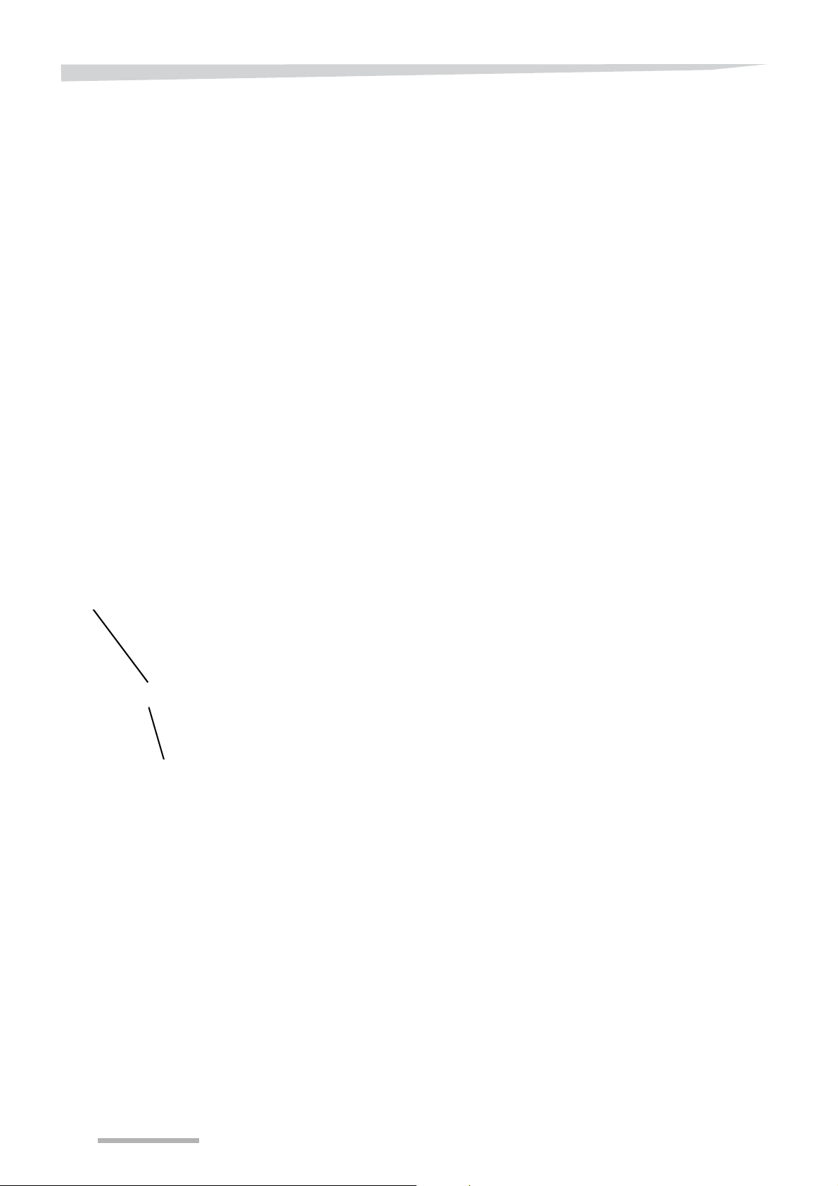
Discharge bushing
Spreading disc
Getting familiar with the machine
Applications of the
machine
Environment
Software
RotaFlow spreading
system
This PTO shaft driven machine is suited for spreading granular
fertiliser on the field and grazing land.
It is attached
• to the three-point power lift of the tractor (Cat. II), or
• to the trailer supplied for this purpose.
Border spreading is possible by using the following:
• border spreading plate,
• tramline cylinder,
• TrimFlow border spreading system.
This fertiliser spreader is equipped with a calibration and border
spreading set that comply with environmental standard EN 13739-1.
This manual contains a description for a control system driven by
software version 1.11 or higher.
This rotary type spreader has two spreading discs. Each has eight
vanes. They are mounted level so that the fertiliser is spread over the
land in a constant horizontal flow. The spreading quantity is regulated
by a dosing plate on top of the spreading disc. Both the dosing pla tes
are located right on top of the discharge bushings.
The fertiliser falls on the turning spreading disc. The discharge point
is determined by the opening in the discharge bushing behind the
vanes. This means that the fertiliser granules are already turning
before they come into contact with the vanes on the spreading disc.
This prevents granules from breaking apart and becoming powdery.
The agitator mounted below in the hopper provides for a constant
stream of fertiliser dust, seeds or granules to the dosing opening(s).
Moreover, the agitator prevents the chunks of fertiliser from blocking
one or more dosing openings.
Adjust carefully
24
The spreader enables you to set the dosing and working width
independently of each other . Moreover, it is possible to shut 2 of the 3
dosing openings so that the application rate can also be set precisely
with a low flowrate, while the risk of blockages remains limited.
Page 25
Getting familiar with the machine
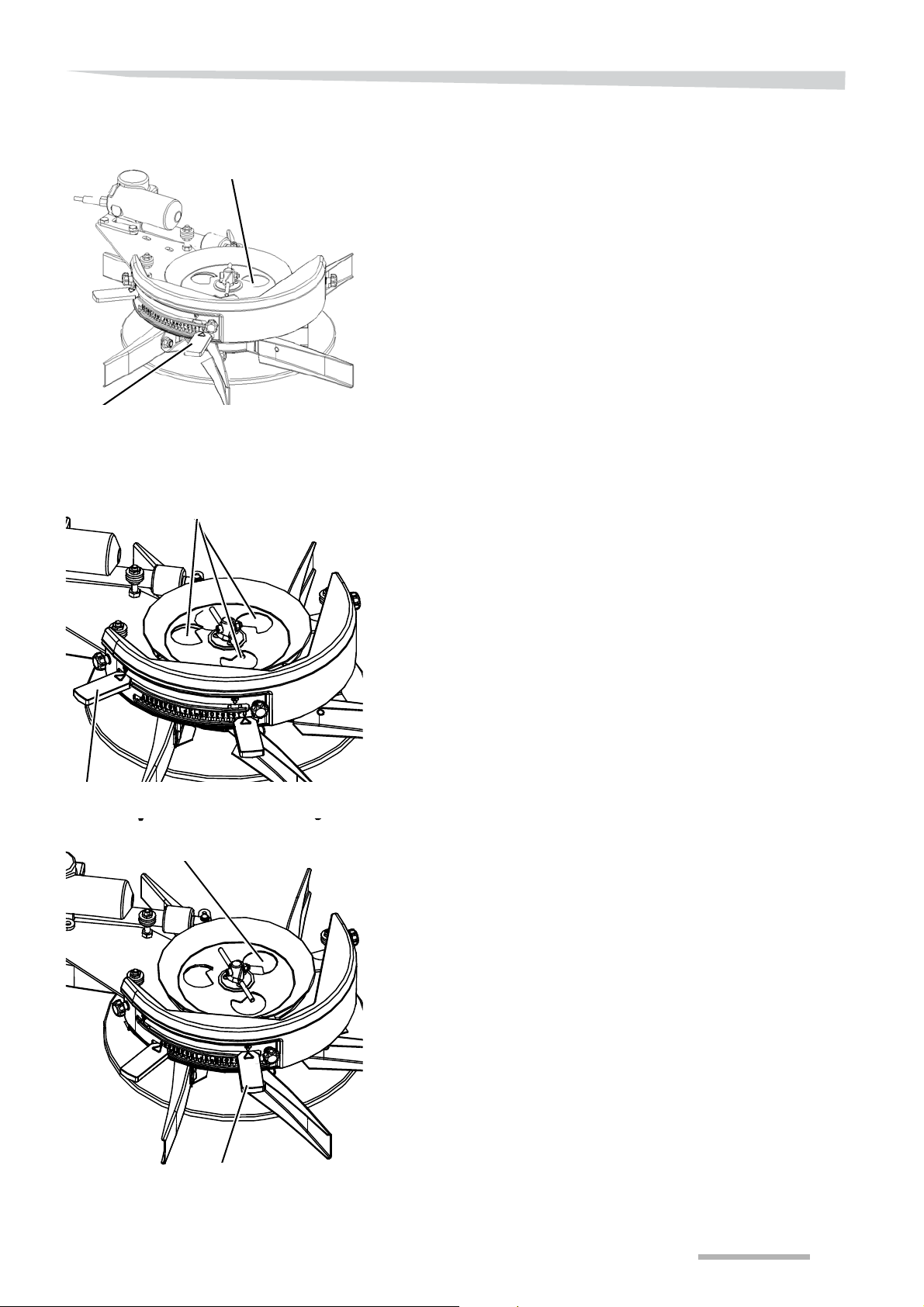
Discharge point adjuster
Dosing plate
Fine application lever
Standard dosing setting
Dosing openings
Fine application lever
Fine application setting
Dosing opening
Application rate
Fine application
The machine is equipped with two actuators at the back, which service
a dosing plate each, in order to provide adjustment of dosing
quantities. This actuator can open the dosing plate in 90 different
positions. The required dosing setting is entered in the main menu of
the control system.
See section »Application rate« on page 112.
The actuators are controlled by means of the spreader operating
system.
One side can be closed off with the selection key under the relevant
symbol on the control box.
Normal dosing
A dosing unit with 3 holes is used per disc to enable one to adjust the
dosing accurately.
Fine application
The spreader is equipped with fine application as standard e quipment
to spread low application rates. This fine application can be adjusted
with a lever per dosing unit.
Low application rates require a small dosing opening. In order
• to finely adjust the settings
• and to counter the blockage
a transition to the opening, which is open wider, is desirable.
2 of the 3 dosing openings are closed when using the fine application
setting.
The dosing is then done through one large o pening, which provides an
accurate and reliable flow, even for very low application rates.
25
Page 26
Getting familiar with the machine
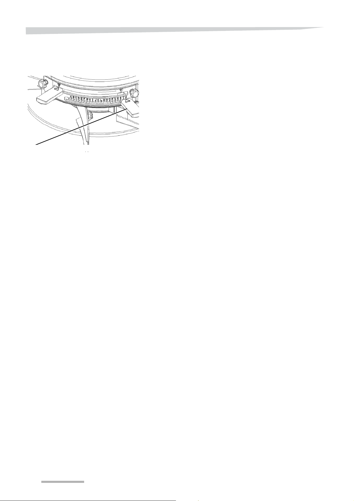
Lever discharge point
Transverse distribution
I
NDICATION
I
NDICATION
The spreading pattern is determined by the transverse distribution.
This is done through the adjustable discharge point.
A handle is mounted at the side of the spreader for setting the
discharge point. This determines the point where the fertiliser
granules come into touch with the vanes of the spreading disc. This
‘discharge point’ setting depends on the type of fertiliser used and the
flowrate in kg/min. This should be adjusted in accordance with the
values given in the spreading chart in order to achieve good
transverse distribution.
The spreading pattern is normally a triangle that completely overlap s.
A trapezoidal spreading pattern may result, depending on the
application rate and working width. This spreading pattern has an
overlapping area of less than 100%.
Check the accuracy of the discharge point by conducting spreading
pattern tests (tray test).
See sectio n » S p re adin g pa tt er n ch eck (tray test)« on page 131.
Take note of the exact driving distance and lay tramlines.
If you want to change the application rate or switch to a different
fertiliser type (with similar working width and driving speed), you only
have to change the application rate setting on the ‘working width and
application rate’ screen of the control system and possibly also adjust
the 'discharge point'.
26
Page 27
Getting familiar with the machine
C B
A
D
Spreading patterns
Full field spreading
pattern
Optimum fertiliser distribution with minimum impact on the
environment can be achieved through the settings and tools
described.
The full field spreading pattern overlaps 100%
A triangular spreading pattern that completely overlaps can be
expected with most fertiliser types with an average working width.
The full field spreading pattern with a trapezoidal spreading
pattern
A trapezoidal spreading pattern could result on large working widths.
The spreading pattern does not completely overlap.
27
Page 28
Getting familiar with the machine
One-sided boundary
spreading with border
spreading plate
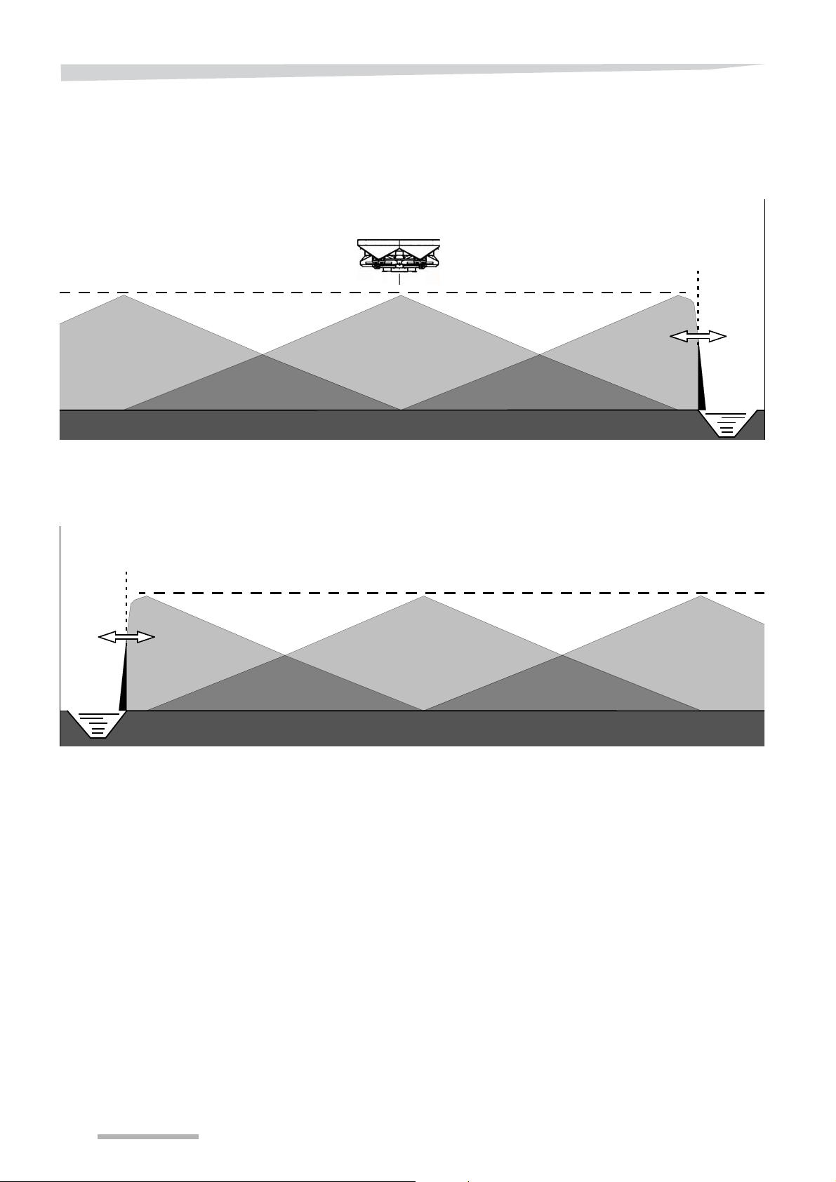
You can drive along the field edge with a half spreading pattern filled
to 100% with the border spreading plate and one closed dosing unit.
You have to optimise the spreading pattern and thereby overcome
environmental pollution when adjusting the border spreading plate.
With the hydraulic border spreading plate, one-sided boundary
spreading is also possible at the left.
28
Page 29
Getting familiar with the machine
1/2 Working width
Environmental setting
Yield setting
Working width
Boundary track
spreading with TrimFlow
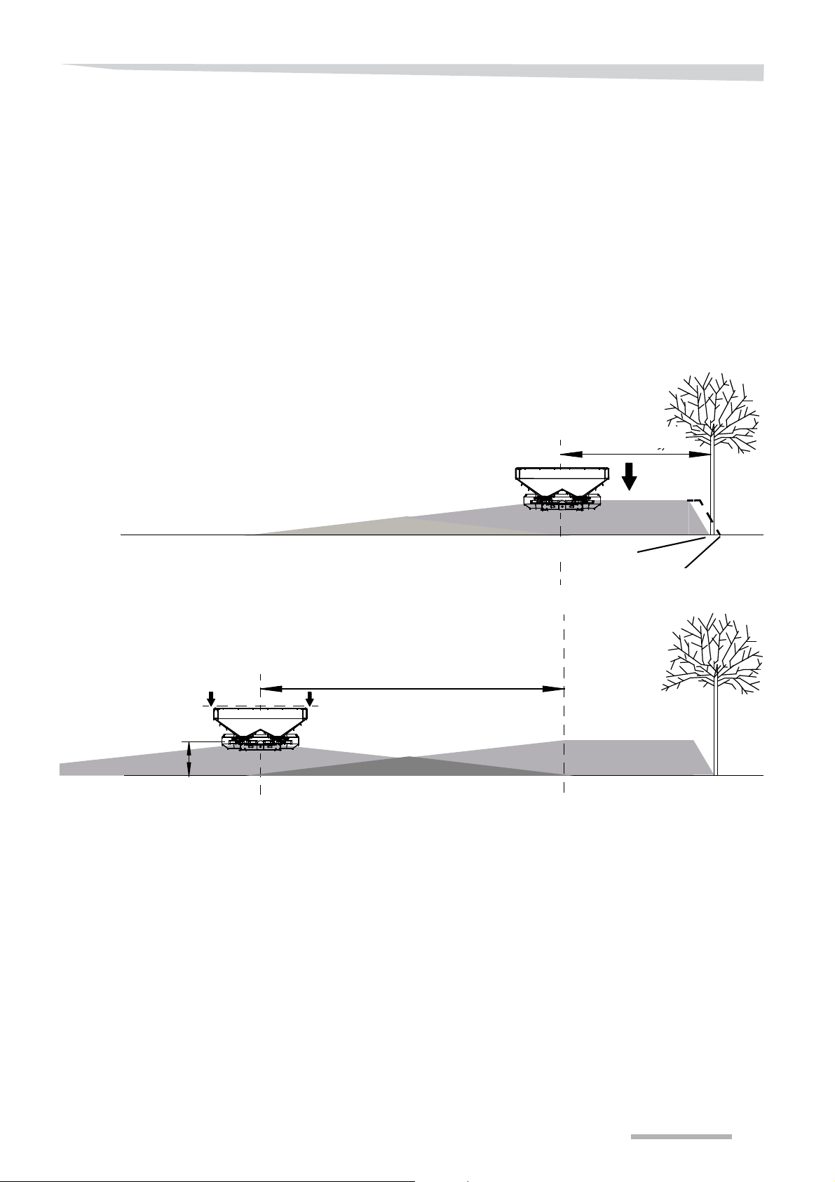
It is possible to spread right up to the border from the first sprayer
tramline with TrimFlow (boundar y track spreading).
Selecting the pattern for border spreading
It is not possible to completely cover the field border at the application
rate and not spread anything above the border. Current environmental
standards only allow for minimal loss over the field edge.
TrimFlow
The TrimFlow deflect s the fertilser granules in such a way that the loss
over the border is limited to a minimum with a spreading pattern which
is as full as possible.
Trimflow has an "environmental setting" and a "yield setting" for
precisely adjusting the border spreading.
29
Page 30
Getting familiar with the machine
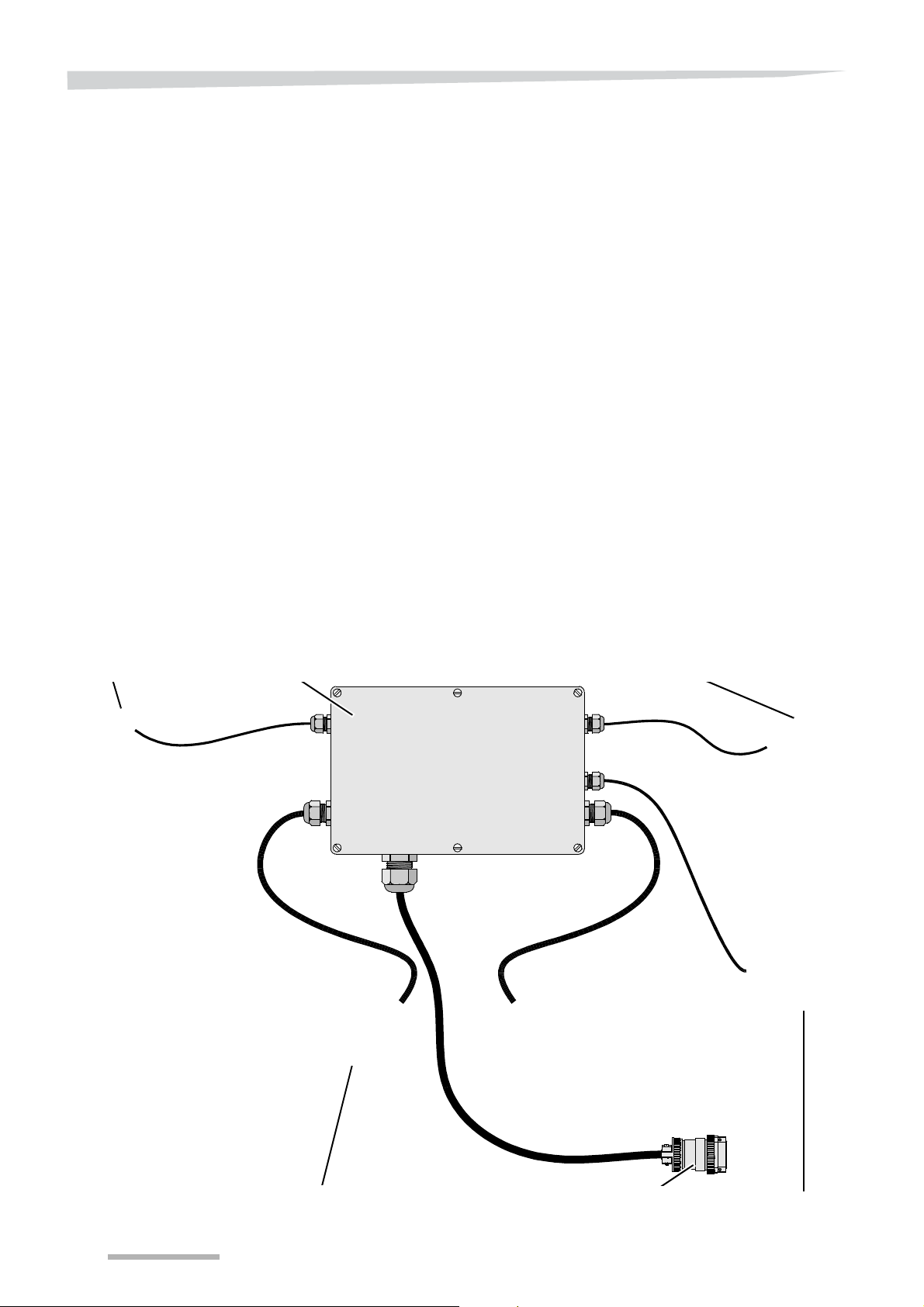
Distribution boxReference sensor
Actuator
ISOBUS communication and power plug
Spreading disc rpm sensor
Weighing
sensor
The ISO control
system
The automatic weighing
system
The ISO control system uses the ISOBUS communication protocol,
which makes it suitable for tractors that are also equipped with an
ISOBUS communication system. For tractors that still do not have an
ISOBUS connection, your dealer can supply an ECU box to which you
can connect all ISOBUS machines.
The spreader uses a weigh cell in the three-point linkage to continuously measure the quantity of fertiliser that is being spread. The
computer in the distribution box compares these values with the set
application rate and corrects as needed by further opening or closing
the dosing unit. The tractor's electronics or an extra sensor measures
the current required driving speed.
See section »Driving speed signal« on page 77.
30
Page 31
Getting familiar with the machine
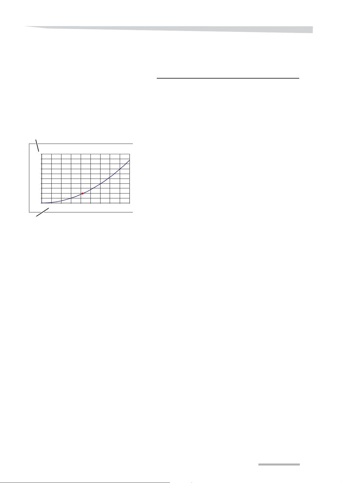
600
flowrate required = (kg/min)
Working width (m) x Driving speed (km/h) x Application rate (kg/ha)
0,0
50,0
100,0
150,0
200,0
250,0
300,0
350,0
400,0
450,0
500,0
0 102030405060708090
Flow rate (kg/min)
Dosing setting
The computer calculates the required fertiliser flow rate with the
following formula:
Automatic calibration
I
NDICATION
With the data from the spreading chart book and the automatic
calibration tests that the spreader carries out every 75 kg or every
minute, the computer determines what dosing setting corresponds
with what flowrate. This relation is different for each fertiliser type, after
all. To determine the relation between dosing setting and flow rate, the
computer needs at least 1 measuring point. This value comes from the
spreading chart. By means of the automatic calibration tests, the
computer repeatedly corrects the relation between flow rate and
dosing setting. In this way, the relation is always current and the
spreader reacts in the right way to changes, for example, in driving
speed or in cases of over and under dosing.
To prevent field conditions such as inclines and holes or steering,
braking actions and vibrations from influencing the measured values,
the machine is equipped with a reference sensor. By means of the
reference sensor signal, the spreader corrects the influence of the
factors mentioned.
If the hopper content becomes less than 100 kg, the control system
switches off the automatic calibration. Measurement accuracy
declines in such a way that new automatic calibration cannot produce
a better discharge curve.
31
Page 32

Getting familiar with the machine
Tellus
control box
IsoMatch
power
Power supply from
tractor battery
Driving speed and PTO
shaft RPM sensor
IsoMatch power cable set
IsoMatch Tellus input
The ISO tractor
Tractor with IsoMatch
ISOBUS tractor connection
The switching functions and data transfer between the tractor term inal
or ISO control box and the machine are operated via the ISOBUS.
Specifically tilling the site and reacting to deviating field forms or soil
compositions is possible through ISOBUS communication.
With GPS, various sensors and management systems are provided
with the necessary information in order to control the machine
optimally.
ISOBUS functionality via IsoMatch
Tractors without their own ISO terminal can work as ISO tractors with
the IsoMatch control box.
Driving speed, RPM and GPS signal on IsoMatch
If speed is not measured on the (drawn) machine, but via the tractor,
the speed sensor or the adapter cable is to be connected to the
IsoMatch to capture the speed signal from the tractor electronics. A
special cable set is required for this.
See section »Directly to the ISO 11786 in cab tractor connection in
the tractor cabin« on page 203.
The same applies for the PTO shaft RPM. The extra sensor is
available for this purpose.
The GPS signal can also be used via the RS 232 on the control box.
This is required for the GEOcontrol functionality.
Also, refer to the manual that comes with your control box.
Conversion to ISO tractor with
IsoMatch power cable set
Adapting non-ISO tractors with IsoMatch power cable set
If the tractor does not have an ISOBUS communication, it can be
added with the IsoMatch power cable set.
Hereafter , your tractor is entirely ISOBUS ready, and you can connect
and operate the machine with the IsoMatch control box.
The driving speed of your tractor (or your drawn machine) is
transmitted via the ISOBUS to the IsoMatch.
The "IM Tellus Input" cable, supplied as a standard item, can be used
for other connections.
32
Page 33
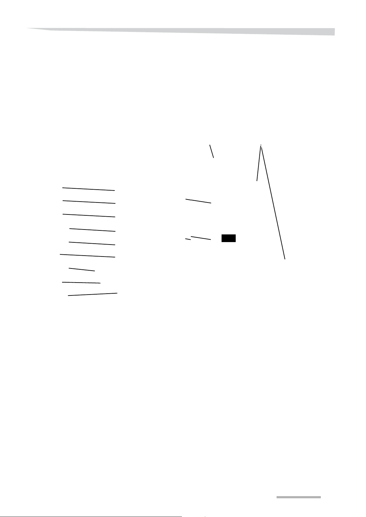
Getting familiar with the machine
Operation with IsoMatch Tellus
Main switch
2 touch screens
Programme
change key
9 pin ISO11783
ISOBUS CAN
ISOBUS
Tractor ECU/
J1939 CANBUS
RS 232
Audio in/out
Camera in
USB 2.0
2-step USB
on 1 hub
RJ45 Ethernet
Configuration
menu key
The control box
The working method and work performance of the IsoMatch control
box are described in this user's manual.
IsoMatch universal ISOBUS terminal
Many functions and programmes on one control box
The divided colour screen has a flexible division to:
• Operate 2 programmes or functions simultaneously on screen, e.g.
the main screen of your machine and a separate ope r atin g program. This can be done without having to switch.
• Operate all keys directly on the touch screen.
• Instruction booklet of the terminal in the correct language on
screen.
• Check the following by camera in the cabin while working:
• a specific point on the machine,
• the crop
• or the vicinity.
33
Page 34
Getting familiar with the machine
• Extra functions:
• Calculator
• Internet browser
• Camera screen (Camera is optional)
• Status bar for time, GPS signal strength and driving direction
• Save and read:
• Documents
• Tractor data
• Field particulars
• Work particulars of various ISO machines.
• Client particulars.
With the main switch on the upper left in the red extension, you can
switch the control box on and off.
Always switch off the control box when you leave the tractor.
If the box is engaged, unintended functions can be activated while you
are in the danger area. Moreover, the control box uses power, as a
result of which the tractor battery could be flattened.
After starting up, the screen with the last (two) selected applications
appears.
34
Page 35
Getting familiar with the machine
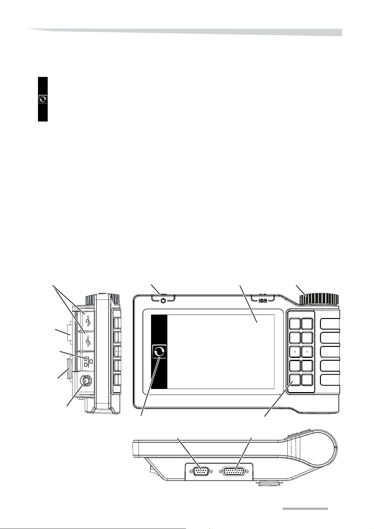
ISO11783
tractor “incab”
connection
9-point
RJ45 Ethernet
Scroll wheel
Main switch
Keys with variable functions
Soft keys
Screen toggle
USB ports
ISOBUS (ITH)
connection
16-point
Video connection
CAN J1939 tractor ECU
RS232 connection
IsoMatch Tellus
Scroll-wheel navigation
NOTE:
Compact and complete
IsoMatch Go, as a handy and more compact varian t of th e do ub le screen version, offers complete ISO control with all functions. Besides
the smaller dimension with the single screen, the number of USB
connections and the absence of Wlan/Wifi constitutes the biggest
difference.
Many additional functions.
The latest developments in ISOBUS communication between tractor
and implement and ease-of-use are all incorporated into the IsoMatch
Tellus GO.
Connect the ISOBUS tractor via IM Tellus 9-point in Cab cable
If your tractor is provided with a full ISOBUS connection, a connection
with the 9-pins in Cab cable between your tractor and the IsoMatch
Tellus GO control box is sufficient.
Other connections are made via the "Input IM Tellus" cable, supplied
as a standard item.
This control box will only be available in limited quantity in 2015.
Consult your dealer for availability .
Quick menu navigation with the scroll wheel and additional keys
A scroll wheel on the upper right of the box makes it easy to scroll
through the menu.
Keyboard linked to screen keys
Keys placed on the right in the hand grip support the control of the soft
keys in the menu and the pop-up numerical keyboard.
35
Page 36
Getting familiar with the machine
Configuration screen
Control box menu
Selecting application
The ISOBUS tool screen
With the configuration screen key , you directly reach the screen where
you can modify the various settings of your IsoMatch.
Consult the user's manual of the control box or tractor for further
information.
Pressing the programme change key will take you back to the basic
screen of the control system on the control box, irrespective of which
screen is currently being displayed. Both screens have their own
programme change key . V arious applications can be used together on
the divided screen in this manner.
Consult the user's manual of the control box or tractor for further
information.
With a programme change key, you can switch between the several
applications or machines in both screens separately.
The uppermost tab displays the ISOBUS tools.
The tractor and tools connected to the ISOBUS can be found here.
Tools tab
The tools screen can be opened with this tab.
Applications screen
The ISOBUS tools screen
The screen displays the following ISOBUS connection:
Tractor ECU
GEOspreader
If you have connected more machines, you can operate the relevant
machines in both screens simultaneously.
The Applications tab
The screen with additional functions can be opened with this tab.
The applications screen
The screen displays the following additional functions:
36
Page 37
Manuals screen
Getting familiar with the machine
Manuals tab
The manuals screen can be opened with this tab.
Manuals screen
The operation manual of the IsoMatch and all other applications are
given here.
• You can go up and down through the list with the arrows
• You open the manual with this key
Back tab
This will return you to the previous screen.
Key functions and the procedure to set or adjust their va lues can be
found in
the user’s manual of your control box.
You will find a graphical overview of the menu structure on page
42.
Entering and modifying
values
Touchscreen operating buttons
Navigation through the menu is done as in the menu structure
described on page 42.
Touch-sensitive screen fields with variable values
The buttons and windows can be operated and opened directly on the
touchscreen.
Entering and modifying values in the menu screens can be done via
the
• Keyboard (pop-up)
• pull down menu
A keyboard or pull down menu appears on the screen as soon as you
touch a value to be changed.
See the below examples.
37
Page 38
Getting familiar with the machine
IsoMatch keyboard
Main screen with GEOspread keyboard
Current working width: 24m
Keyboard (pop-up)
Let us suppose that you want to change the working width:
Touch the working width value in the main screen.
The keyboard comes up in the main screen.
Value to be modified
The values chosen by you on the screen are shown at the top of the
keyboard displayed. Enter here the working width of 24 metres.
You can immediately change the displayed value with the keys.
Saving change
38
The change is saved when you press the OK button.
Thereafter, you can choose a following value in order to change it.
Interrupting change
The change menu is interrupted with the "Cancel" key and control is
returned to the menu. The original value on the screen remains
unchanged.
Page 39
Getting familiar with the machine
Discharge point letter pull down menu
Main screen of GEOspread
pull down menu
Before choosing a given application or letter value, a menu of the
value to be changed with various choices below one another may
appear after the touch. We call it a pull down menu in this manual.
You want to change the discharge point letter value:
Look for the new letter value in the spreading chart
Touch the letter value in the main screen.
The pull down menu opens up on the screen.
Scroll, if required, to the correct letter with the arrows
Select the new letter on the touchscreen
Touch the new letter to be chosen
The pull down menu closes and the new letter is set.
Other control box or tractor terminal
The display of screens and key functions could differ slightly in a
tractor with an ISOBUS communication system through an
independent terminal. The ISO-tractor terminal may have 5 or 6
buttons left or right of the screen. In that case, you can use a switching
key to alternate between toolbars with key functions beside the
screen.
I
NDICATION
Key functions and the procedure to set or adjust their va lues can be
found in
the user's manual of your control box or tractor terminal.
You will find a graphical overview of the menu structure on page
42.
Although your screen offers the control keys to the right, the keys are
indicated to the left and right in the graphical overview of the menu
structure.
The control box does not have a separate feeder cable. The ISOBUS
plug that you plug in behind the control box also contains the supply.
39
Page 40
Getting familiar with the machine
Menu structure of spreader
Main menu
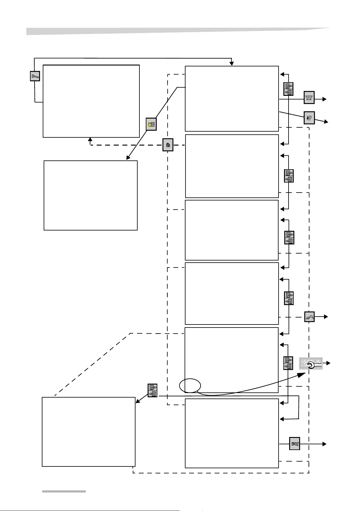
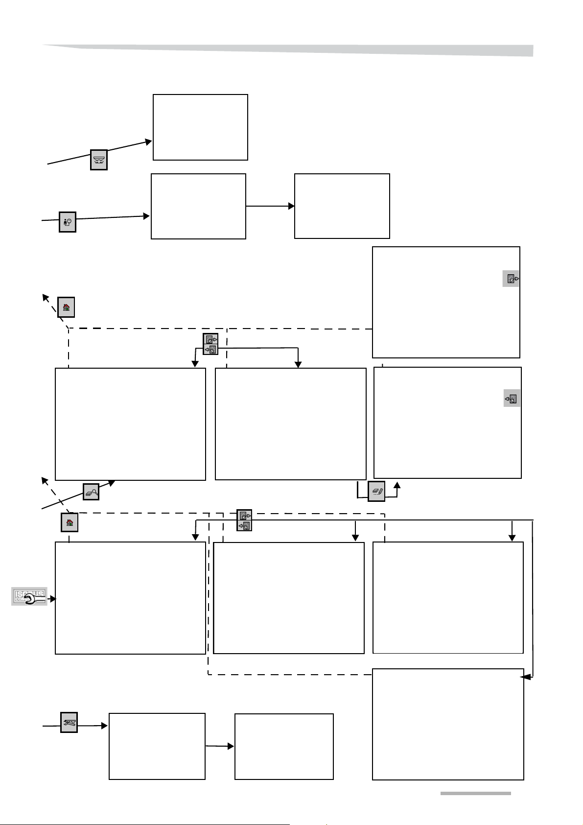
The operating system (the software) of the control system has 4
levels:
• Main menu with spreader functions that you need during spread-
ing,
• Settings and service menu with basic settings and functions that
you need before or after spreading,
• Diagnosis menu for identifying faults in the event of failure
• ISOBUS communication menu for various terminal- and machine-
related settings.
You will find a graphical overview of the menu structure on page
42.
By pressing the home key , you can return to the main scree n from any
random point in the program.
With some types of ISO control boxes, change the functions of th e
function key by pressing the change key.
In the main menu you will find all the information related to the
spreading process or the machine while spreading. Moreover , you can
use the function keys to carry out the most important functions
immediately, such as over and under dosing or closing a spreading
disc.
Settings and service menu
Diagnosis menu
In the first screen of the settings and service menu, you must enter
some necessary data for correct spreader operation before use. For
some functions, such as emptying the hopper, calibration te st and field
registration, there is a function key that takes you to a following
function-specific screen.
Pressing the key symbol accesses the first screen of the settings and
service menu.
By pressing the scroll keys, you reach the next screen of this menu.
There you will find settings that you do not have to modify regularly.
Behind the PIN code, there are screens where you alone must make
changes in the event of any modification to the machine.
Y ou can reach the diagnosis menu from any screen of th e settings and
service menu by pressing the lens key.
By pressing the scroll keys, you can browse the diagnosis menu
screens. The values in this menu serve to identify faults and do not
have to be modified.
By pressing the key switch, you can return from any diagnosis menu
screen to the 1st screen of the settings and service menu.
40
Page 41
Getting familiar with the machine
Feeder cable
ISOBUS plug
Speed signal
CAN plug
ITH connection
ISOBUS communication menu
Focus II control box
Pressing the ISOBUS symbol accesses the first screen of the ISOBUS
communication menu.
In the ISOBUS communication menu, you can change the settings of
• terminal use,
• external control,
• data storage,
• licence use,
• and data of machines to be connected.
By pressing the scroll keys, you reach the next screen of this menu.
As an alternative to the ISOMatch Tellus control box, the Focus II control box is available. This control box has a black-and-white screen
and fewer function keys beside the screen. Furthermore, this control
box has fewer possibilities for communicating with an external system.
The tractor and spreader need to be adapted somewhat to be able to
use this control box. Consult your dealer.
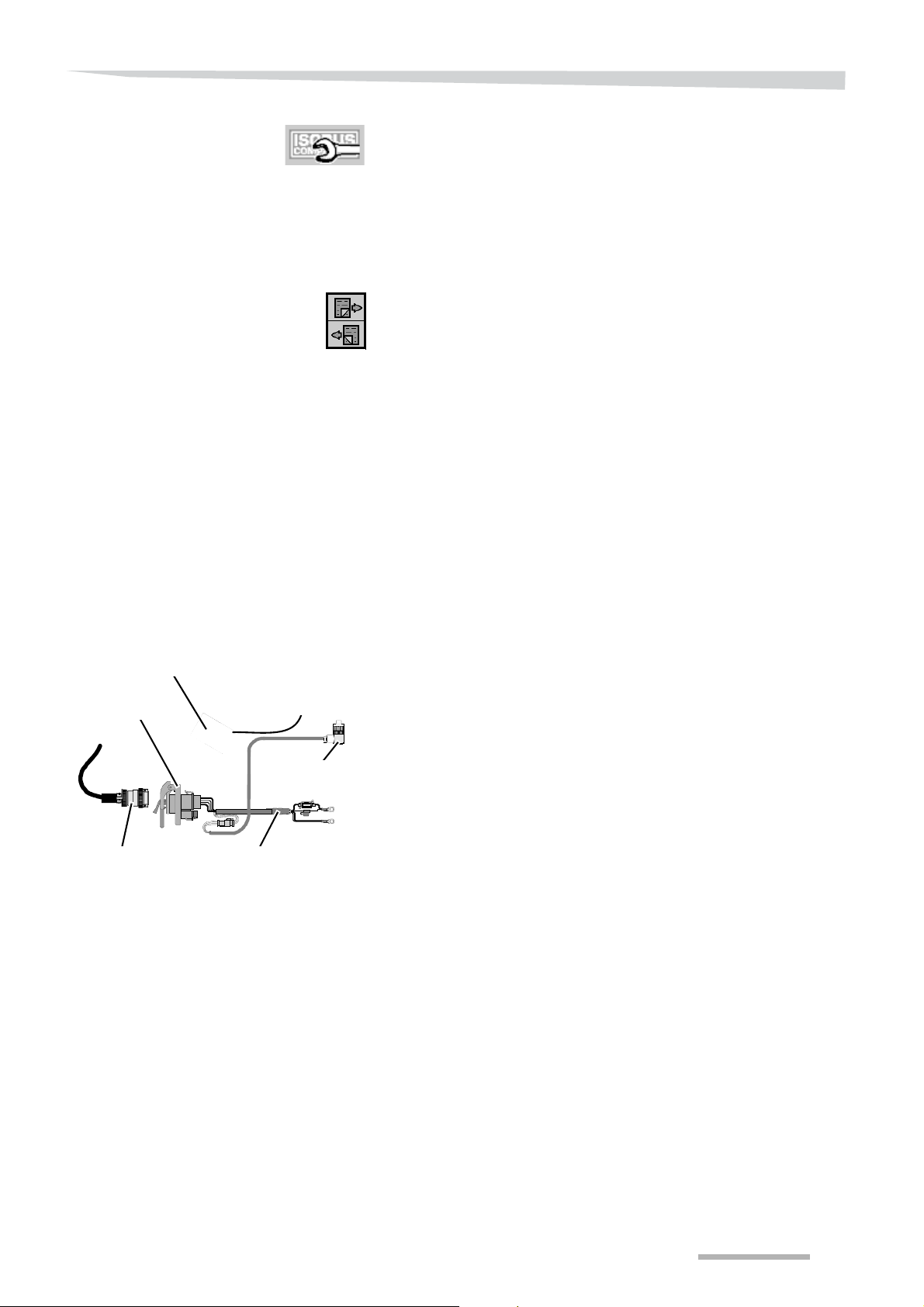
ITH connection
Spreaders equipped with an ISOBUS communication system can be
operated with ITH or Focus II control boxes. The ISOBUS communication and power plug is connected to the ITH. The ITH must be connected to the control box and the battery poles. The ITH provides
communication to the machine and electric power supply to the machine and the control box. The ITH is not a proper ISOBUS communication system for your tractor.
41
Page 42
Getting familiar with the machine
Menu structure
42
Page 43
Getting familiar with the machine
43
Page 44
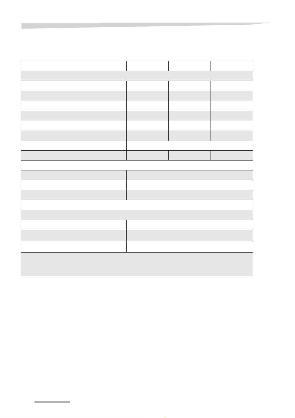
Getting familiar with the machine
Technical specifications
Type RO-M EW 1100 RO-M EW 1550 RO-M EW 2000
General
Content of the hopper (l) 1100 1550 2000
Filling level (cm) 100 119 138
Filling width (cm) 214 214 214
Hopper's width (cm) 220 220 220
Weight*(kg) 400 425** 450**
Maximum load capacity (kg) 2000 2000 2000
Type of linkage pins Cat. II
Maximum total weight (kg) 2525
Spreading
Working width (m) 10, 12, 15/16, 18, 20/21, 24, 27/28 (option)
Fertiliser application rate (kg/min) 10-280
Rotational speed of PTO shaft (rpm) 540
Lubrication
Grease type EP 00/000
Content of central gearbox (cm3)
Content of spreading disc gearbox (cm
3
)
200 +/- 20
180 +/- 20
* Including three-point weighing unit
** Including hopper extension
44
Page 45
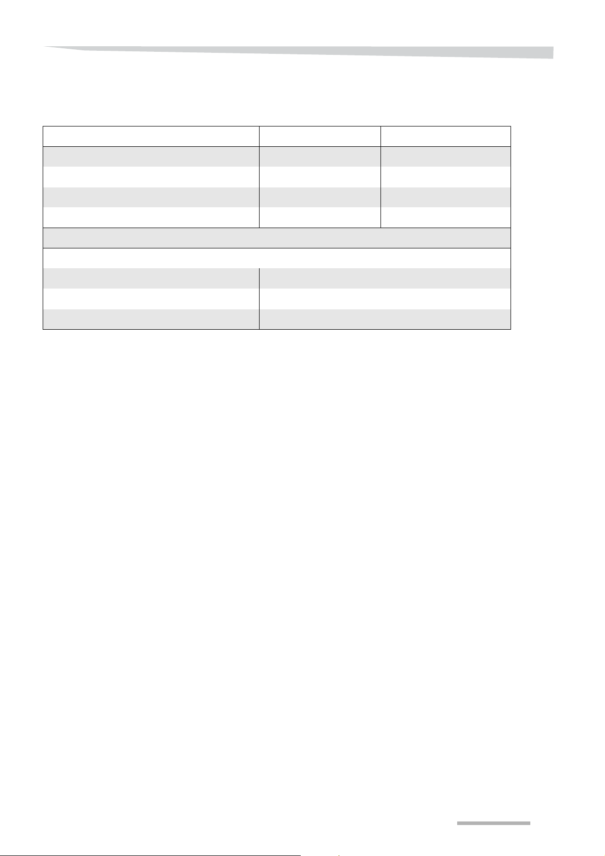
Getting familiar with the machine
Sound level Closed cabin Rear window opened
Tractor at 540 rpm (dB) 70.4 75.7
Tractor + operating, empty spreader (dB) 71.4 81.0
Tractor + spreading spreader (Kali 60) (dB) 72.7 84.2
Tractor + spreader (Kali 60) + TrimFlow (dB) 70.9 85.5
Miscellaneous
Tractor power (kW) 44
Electrical supplies required 1 ISOBUS socket outlet + 1 trailer socket
Number of hydraulic valves on the tractor 1 valve with equipment with Trimflow
45
Page 46
Before first use
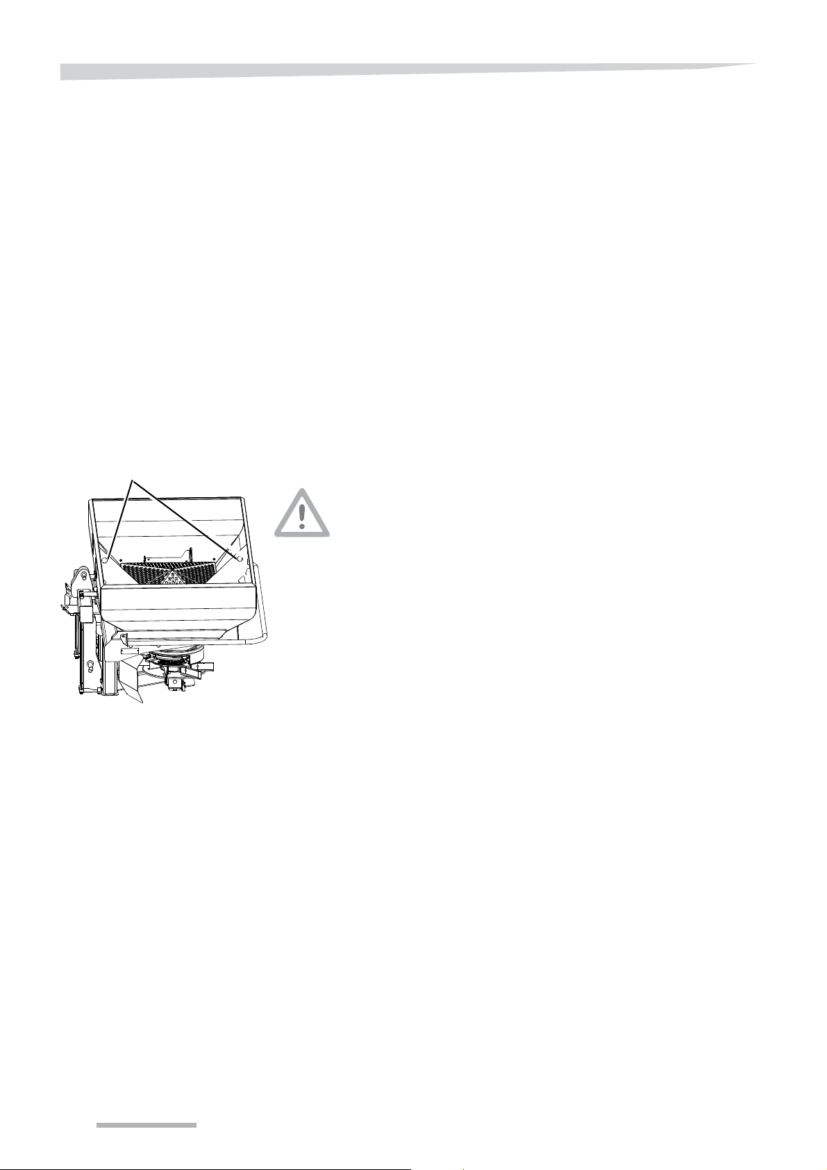
Hoisting points
Before first use
Inspect the supplied
machine
Mounting instructions
TIP
The machine would generally be assembled and delivered ready-foruse by the dealer . The dealer is also responsible for pr oviding instructions for use and maintenance. He/she must also ensure that the
required documents are provided, such as:
• manual,
• spare parts manual
• spreading chart book,
• testing and approval documents where required.
If parts are missing or have been damaged during transport, you
should report that to your dealer directly on delivery.
Before the machine can be used, various parts and supplied
accessories must be unpacked and assembled.
In addition to these assembly instructions, use the parts book to locate
the parts and their positions on the machine.
Use sturdy hoisting equipment
Use the hoisting points on the machine to hook up your approved
slings or hoisting chains.
If the machine is hoisted incorrectly or with inferior equipment it could
fall from the sling, resulting in material damage and possible physical
injury.
Work on a clean surface
Before you start mounting, you should clean the surface and the
immediate surrounding area where you place the machine.
A machine that is placed on pieces of packaging or parts, may slide
away during mounting with material damage and possible physical
injury as consequence.
Accessories and parts must be correctly mounted
Assemble accessories and parts according to specifications and
attach them only for their designated pu rpose; ensure that they are
locked correctly. Accessories and parts not mounted properly could
lead to personal injury and damage to the crop and machine.
46
Page 47

Before first use
Tighten all bolts and nuts
Check that all the nuts and bolts are well set. Check this again after
one hour of use
• after delivery and
• after maintenance or repairs have been carried out.
Never check holes to be lined up by inserting your fingers
Use a pin for this purpose. Movement of the machine or parts may
cause severe physical injury.
Be careful that nothing gets jammed
It is easy for parts to get jammed while mounting the spreader.
Work carefully when mounting by:
• placing the machine on adequate supports,
• switching off the PTO shaft,
• releasing the pressure from the hydraulic system,
• switch the control box off,
• switching the tractor off and removing the key from the ignition,
• engaging the parking brake of the tractor,
• wearing protective clothing, such as safety gloves and shoes,
• carefully performing only the action described,
Being jammed in could cause physical injury.
47
Page 48
Before first use
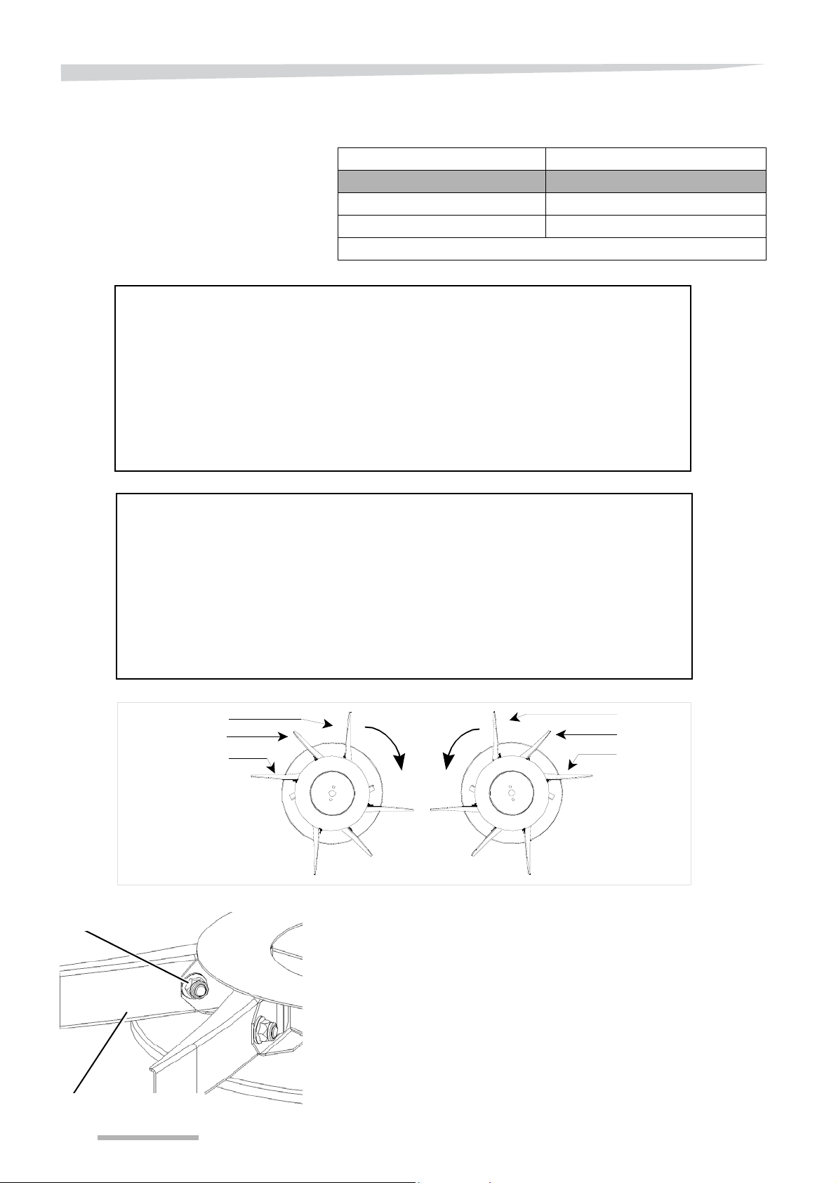
285
(11
1/4
")
285
(11
1/4
")
235
( 9
1/4
")
285
285
235
24-28
m
(7 8- 92 ft)
Optional
Lock nut
Vane
Vanes
Three vane combinations, as illustrated in the diagram, must be used
for different working widths.
Working width (m) Vane combination
10-18 135-185-235
20-24 185-235-285
24-28* 285-235-285
* Optional
Vane position on the disc
48
Grease the threaded rods of the vanes.
Hook the small vanes at the first position behind the fixed vanes.
See the illustration given above.
Then place the medium-sized ones, followed
by the larger vanes.
Press the vanes in well and put the lock nut in position.
Mount the vanes on the other side of the spreading disc and onto
the other spreading disc in the same manner. Place vanes o f equal
length across from each other. See the illustration given above.
Fasten the lock nuts (50NM)
Page 49
Before first use
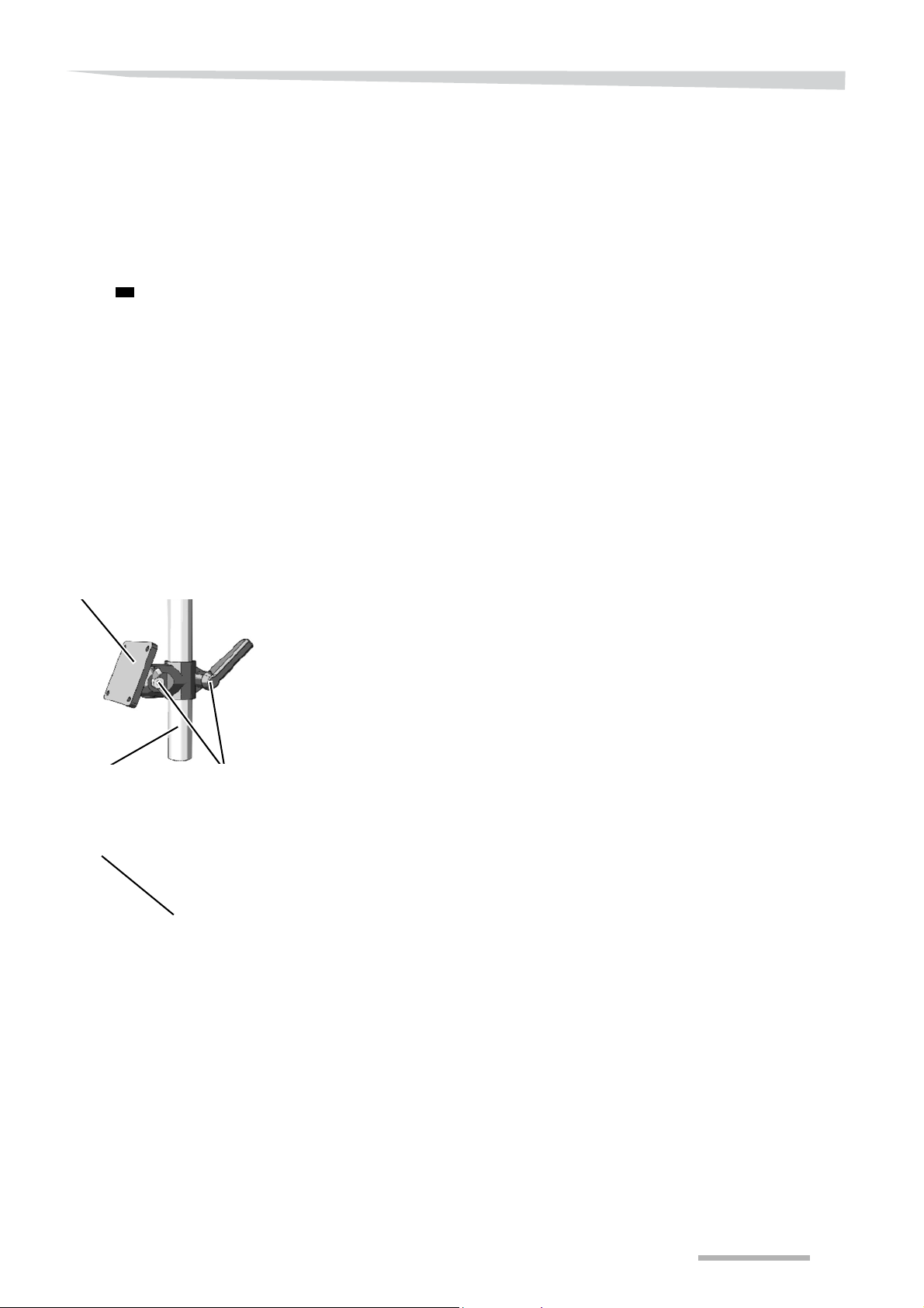
Pipe
Console for the control box
Swivel range
Console on mounting level
Control box
Console assembly
If you use the IsoMatch or another loose-standing control box to
operate the spreader, you must first assemble the support.
The fixing materials and the assembly instructions are delivered with
the control box. Additionally, you will find brief assembly instructions
below.
If you use the IsoMatch or another loose-standing ISO-control box
with a tractor equipped with the ISOBUS communication system, you
can connect it with the supplied 7 points CAN cable to a standard
tractor CAN connection.
Connect the side of the cable to which 1 plug is attached to the
tractor CAN connection.
Connect the side of the cable to which 2 plugs are attached to both
control box connections.
If you use the IsoMatch or another loose-standing ISO-control box
with a tractor that is not equipped with the ISOBUS communication
system, you need a tractor ECU. Your dealer can supply this. This
tractor ECU has an outgoing 7 point CAN plug.
Connect the CAN-plug to the control box.
Mount the control box in a place where it would:
• be well visible,
• easy to operate while spreading,
• and result in minimal visual hindrance while driving the tractor.
The console has two range and height adjustments to provide optimal
view of the control box.
Mount the console to the back of the control box with the
accompanying fixing material.
Mount the pipe for console foot to a firm base.
If there is no suitable place in the cabin a footplat e should be made to
which the pipe can be welded.
Weld a footplate to the pipe for it to be assembled on the selected
level in the cabin.
Ensure that there is sufficient free room behind the assembly level
for drilling and assembly activities.
Drill a hole pattern in the footplate and on the assembly level in the
cabin.
Mount the foot of the console.
Place the control box on the base of the pipe.
Bundle excessive power cable together with cable ties.
Also refer to the manual that comes with your control box.
49
Page 50

Before first use
IsoMatch terminal on an ISO
tractor
IsoMatch terminal on a NONISO tractor
If you use the IsoMatch, Tellus or Focus II control box in a tractor
equipped with the ISOBUS communication system, you can connect
it with the supplied 7-pin CAN cable to a standard tractor CAN
connection.
Connect the side of the cable to which 1 plug is attached to the
Connect the side of the cable to which 2 plugs are attached to
If you use the IsoMatch control box with a tractor that is not equipped
with the ISOBUS communication system, an extra cable set is
needed. This cable set is included in the order or can be supplied via
your dealer.
With the non-ISO adaptor cable set, you can equip any tractor type
with a full ISOBUS communication system.
The fixing materials and the assembly instructions are delivered with
the IsoMatch control box.
See also section »IsoMatch universal ISOBUS terminal« on page
tractor CAN connection.
control box connections.
33 and the description from page 201 .
50
Page 51
Before first use
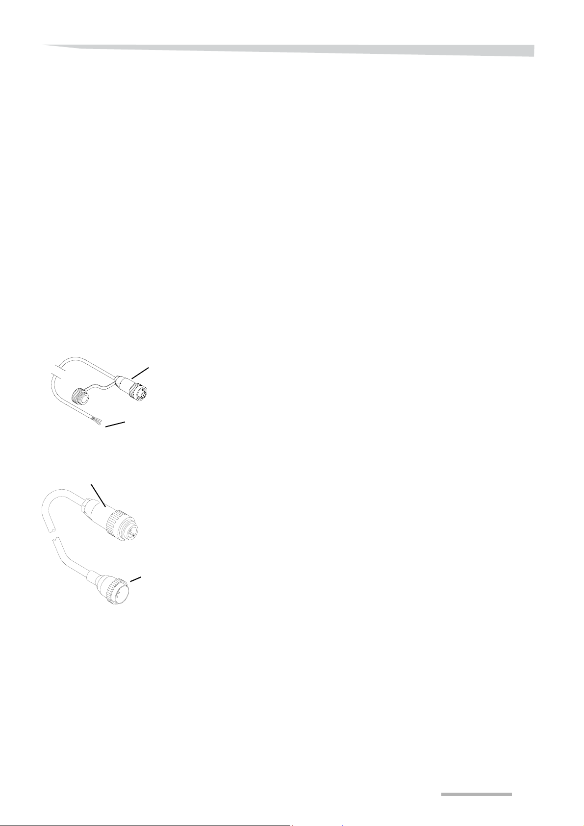
Tractor radar side
Tractor ECU side
Tractor ECU side
Tractor radar side
Driving speed signal
Tractor radar or electronic
unit
To function well, the spreader needs a driving speed signal. In tractors
equipped with the ISOBUS communication system, the tractor takes
care of the signal. Tractors equipped with a tractor ECU can receive
the signal from the tractor electronic unit, tractor radar or wheel
sensor.
If you want to use the driving speed signal of the GPS receiver on the
tractor, you should connect the plug behind the control box. Then
switch on the appropriate external signal as described in
section »Driving speed signal« on page 77
and the reception of an external signal and the required speed
reduction,
section »Set ISOBUS communication« on page 88.
See also the user's manual of the
• control box,
• tractor ECU,
• tractor,
• sensor.
To connect the tractor ECU to the tractor radar or tractor electronic
unit, a number of brand-specific cables are available.
See section »Tractor ECU driving speed signal« on page 204 and
the spare parts manual or consult your dealer.
Wheel sensor
First fit the universal plug to the tractor ECU.
See the tractor ECU user's manual.
Check the pin occupation of the plug or socket of the pulse
generator.
Then fit the specific cable between the universal plug on the tractor
ECU and the tractor radar or electronic unit.
When using the universal cable between the tractor ECU and tractor
radar or electronic unit:
Connect the blue wire to one of the radar's negative poles.
Connect the brown wire to the driving speed signal.
Also see the tractor or radar user's manual.
If the tractor does not have a pulse generator for driving speed
measurement a wheel sensor can be placed over a rotating object.
This object must be connected with the front wheels in order to obt ain
a reliable reading. Few options are:
• reinforcement strips from the front hub,
• lug bolt heads in the hub,
• intermediate shaft to front wheel drive,
• wheel ring.
51
Page 52
Before first use
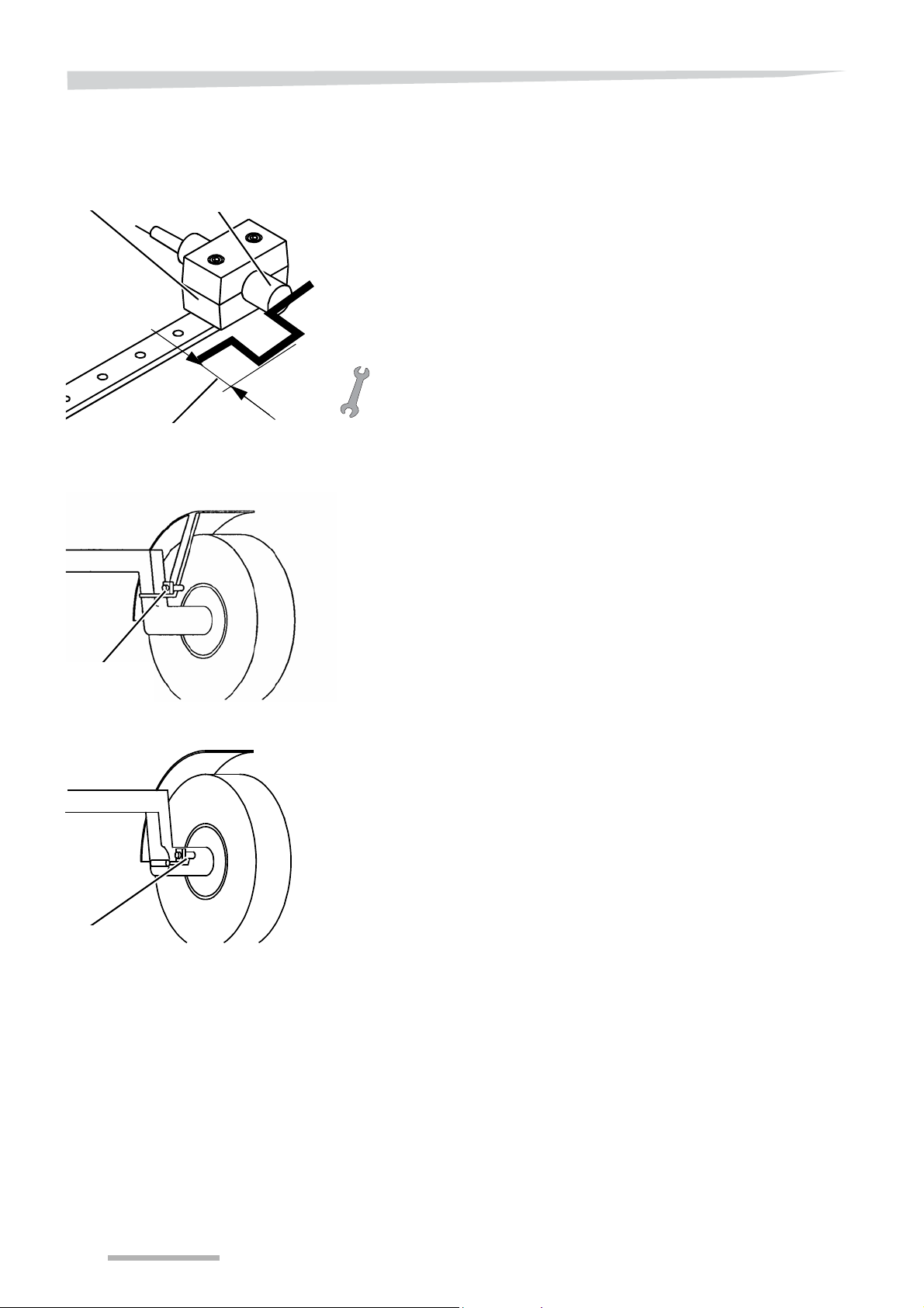
Clamp or
support
Stub axle
Minimum 12 mm
Sensor clamp Wheel sensor
Assembly of the wheel
sensor
Select a part that stands out suf ficiently high, minimum 12 mm. Behind
this point there must be a space where the speed sensor would not
pick up any metal for it to transmit a pulse.
Weld a strip or bolt head to the flange nuts of the drive axle in order
to obtain a linking distance.
Mount the sensor, on the opposite side of the switching point, in
line with the driving direction of the turning part, such as
• the bolts on the stub axle or
• a place for a clamping bracket on the round part of the wheel
axle.
Select a point that is as high as possible, in the lee of the axle. This
will ensure that the sensor will not get in touch with high crops.
Ensure that the clamping bracket is well supported by at least two
bolts so that the sensor would not vibrate or move away from the
wheel ring.
If there is no suitable bolt or clamp connection:
Drill the centre points in the wheel or stub axle.
Tap screw thread into the drilled holes.
A non-elastic brace could be made from the strip provided, onto
which the sensor can be mounted.
Adjust the sensor as described in
section »Setting the wheel sensor« on page 54.
Feed the cable to the tractor ECU.
Fit the wires in the tractor ECU as described in
the tractor ECU user's manual.
Ensure that:
• The cable runs away so that the operating system cannot stand on
it and cannot trip on the cable,
• the cable gland must not be sharp,
• the cable material can be tied together with cable ties,
• the cable must not be attached to moving or hot parts,
• the cable of the wheel sensor must never be te nsed with full wheel
extension.
52
Page 53
Before first use
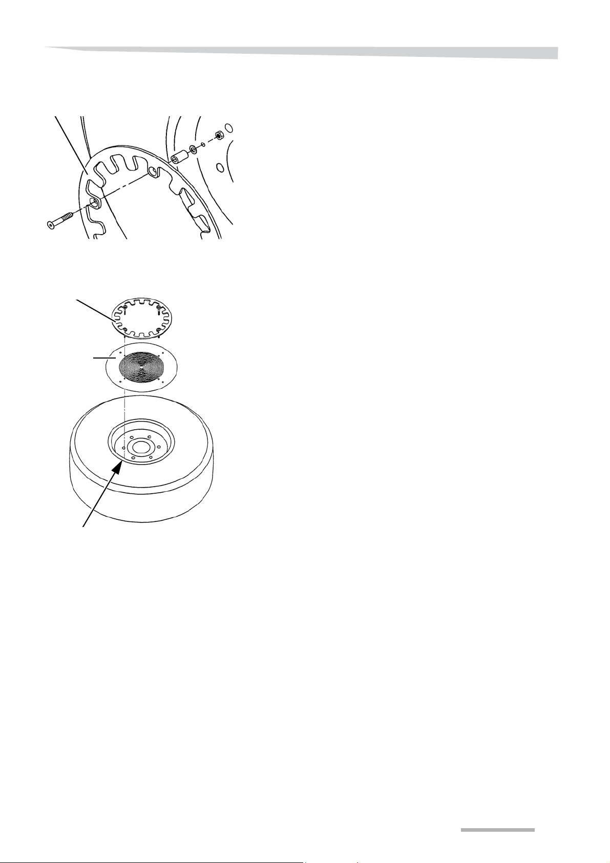
Wheel ring
Outline of bolt holes
Drilling jig
Wheel ring
Wheel ring
Wheel ring assembly
A greater number of pulses per wheel rotation provides a more
accurate speed measurement. 250 pulses per 100 metres is the
minimum required value.
If you do not attain the desired number of pulses with the wheel sensor
against a part of the tractor, two types of wheel rings can be supplied:
• wheel ring 350 mm,
• wheel ring 420 mm,
The 420 mm size ring is divisible.
It is recommended that the front wheel of the tractor be removed in
order to mount the wheel ring.
Engage the parking brake of the tractor.
Loosen the wheel nuts at the front wheel by one turn.
Lift the wheel from the ground.
Support the font axle with a suitable support.
Remove the wheel nuts completely.
Remove the wheel and lay it down where it would be stable, with
the inner part facing you.
Mount the fastening bolts with the injection bushings and nuts on
the wheel ring.
A drilling jig is provided to ensure that the wheel can be well centred.
Slide the drilling jig over the ends of the bolts.
Place the rings on the inner side of the front wheel.
Centre the ring on the hole in the rim with the drilling jig.
Mark the bolt holes.
Drill the bolt holes in the rim.
Mount the wheel ring to the rim.
Mount the front wheel of the tractor.
Ensure that the weight of the tractor remains on the axle so that the
wheel can turn freely.
Remove possible oscillation in the wheel ring by shifting the nuts
and check nuts on the wheel ringbolts.
Fit the wheel sensor in the clamping bracket in such a way that the
middle of the wheel sensor lies against the middle of the wheel ring
cams.
Remove possible oscillation in the wheel ring with the nuts and
check nuts.
53
Page 54
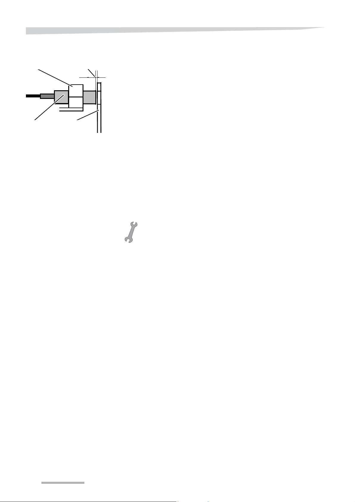
Before first use
Sensor Wheel ring
Clamp
Clearance of 3.5-4.5 mm
Setting the wheel sensor
The wheel sensor must never touch the cams of the wheel rings!
Set the space between the wheel sensor and the cams to 3.5 mm
for the wheel ring with a diameter of 420 mm and 4.5 mm for the
wheel ring with a diameter of 350 mm by shifting the whee l sensor
in the clamp.
Fix the locking bolt.
Indication
If the distance between the wheel sensor and wheel ring is too great
the wheel sensor would not recognise the various cams. Then no
pulses are given off and the system does not measure the driving
speed. You can check and test the operation of the sensor by means
of the indicator light that is fitted behind the sensor. If the wheel sensor
recognises a separate cam or anot her measurin g point, the indicator
light comes on. If the cam or measuring point is past, the indicator light
must go out again.
Wheel sensor cable
Lay the cable to the tractor ECU and connect it.
See the user's manual of the tractor ECU, control box or tractor.
Tie the cable down.
Lead the cable of the wheel sensor in such a way that it never
becomes taut during complete wheel extension.
54
Page 55
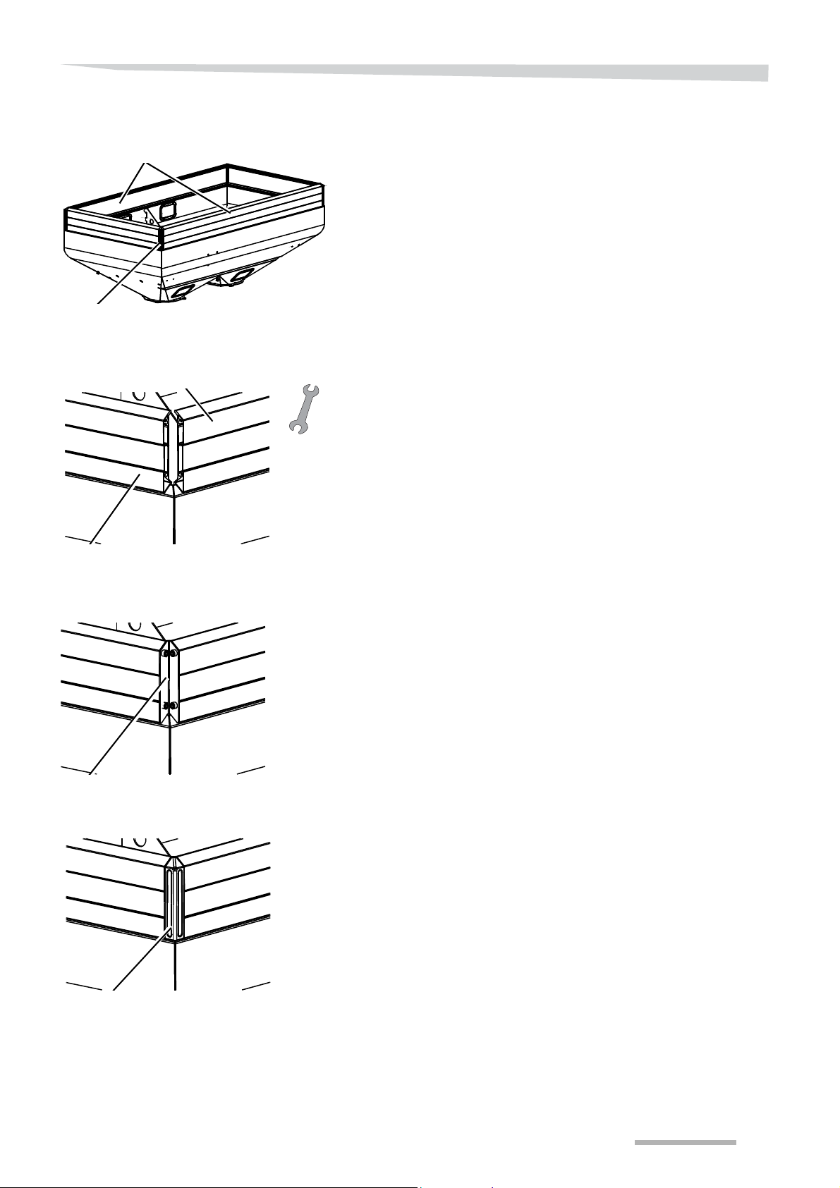
Before first use
A long side
A corner part with a covering baffle
Short side
A long side
Corner part
A corner piece with a cap
Hopper extension
A hopper extension increases the load capacity of the spreading
hopper. All edges consist of:
• 2 long sides,
• 2 short sides,
• 4 corner parts,
• 4 caps,
• fixing material.
For correct use of the fixing materials, see the spare parts manual.
Put a long and short edge on the coaming.
Attach a corner piece with the fixing materials.
Tighten the fixing materials by hand.
Attach the next long side to the coaming.
Attach a corner piece with the fixing materials.
Attach the next short side to the coaming.
Attach the last corner piece with the fixing materials.
Fasten the fixing materials. The torque should be 30-35 Nm.
Put the caps on the corner pieces from the top.
Press the cap until it clicks in position.
Put the reflector stickers on the corner pieces.
All other edges have to be mounted as described above.
55
Page 56
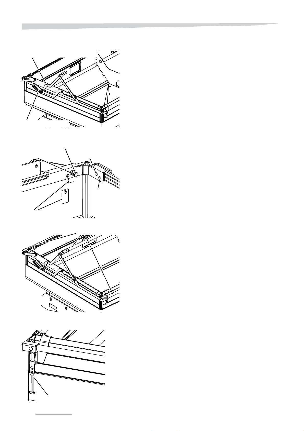
Before first use
Rotation gear
Handle
Locking bolt
Lock nut
Clamp
Hopper
Hopper extension
Tubes
Elastic band
Hopper cover
The hopper cover must be mounted on top of the hopper or hopper
extension to protect the contents against rain and spray water.
Also see the spare parts manual for the correct assembly.
Place the rotation mechanism on the coaming or hopper extension.
The rotation mechanism with the handle must be placed on the left
side.
Fix the lock nut completely onto the locking bolt.
Keep the clamp between the coaming or hopper extension and the
rotation mechanism.
Mount the locking bolt through the correct hole and clamp:
• the lowest holes are for mounting the hopper,
• the uppermost holes are for mounting the hopper extension.
Fasten the locking bolt against the coaming or hopper extension.
Turn the lock nut on the locking bolt against the rotation
mechanism.
Put a tube through the opening in the middle of the canvas. The
fastening plates on the outer edges of the tube must always be
turned with the round side facing upwards.
Fit the tube to the rotation gear.
Put the remaining tubes through the openings in the front and back
sides of the hopper cover.
Fit the tube and the hopper cover to the rotation gear. Put the bolt
through the plate on the head of the tube through th e hopper cover
as well. Do not forget to fit the elastic!
Fasten the fixing materials. The torque should be 30-35 Nm.
56
Page 57
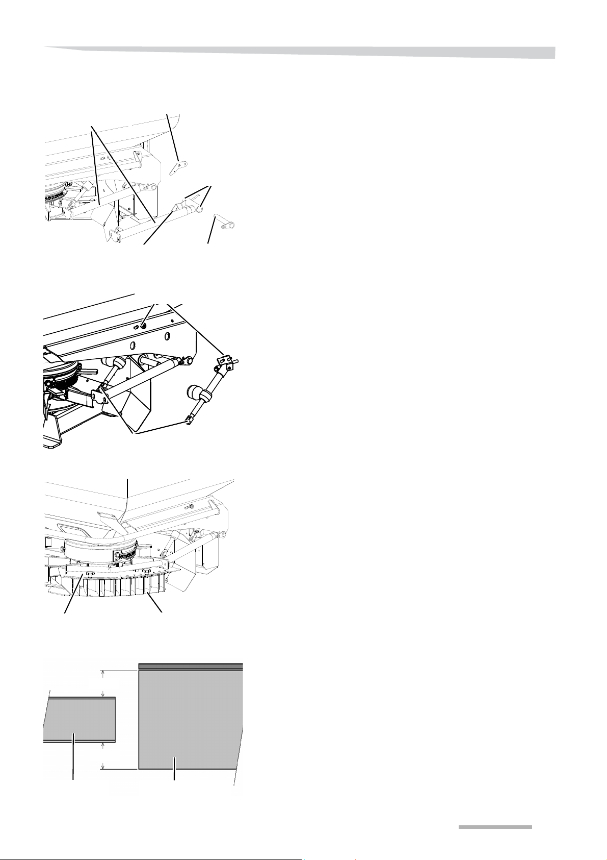
Before first use
Sensor plate
Pipe with hinge point
Hinge pin
Hinge bushing
Mounting the magnet
Bracket with cylinder
Fork
Laminated box
Top plate
21,5
21,5
Slotted box
Vane
TrimFlow
The TrimFlow is used for border spreading from the sprayer tramline.
Attach the pipe with the hinge bushing to the spreader frame:
Mount the magnet to the plate on the pipe.
Put the pipe with the hinge bushing in the spreader frame.
Mount the hinge pin to the frame and the hinge bushings.
Lock the hinge pins on both sides with the securing bolts.
Mount the sensor on the sensor plate.
Mount the plate with the position sensor with the fastening bolt.
The plate must face downwards and the sensor outwards.
See the parts book for correct mounting.
Mount the hydraulic control:
Mount the bracket to the cylinder.
Mount the entire unit on the spreader.
Attach the cylinder fork to the pipe hinge point.
Attach the slotted box to the pipe with the top plate.
Set the slotted box horizontal using the slot holes in the bracket of
the cylinder.
Set the slotted box in the middle of the vane using the slot holes in
the top plate. The distance must be 21.5 mm above and be low the
vane.
Allow the hydraulic valve to run for a few seconds to bring the
TrimFlow in working condition and pressurise in the accumulator.
57
Page 58

Before first use
Plate with sensor
Magnet
Plate with sensor
Magnet
Check the operation of the position sensor in working position:
Set the plate with the sensor opposite the magnet.
Start the tractor and engage the control box.
Check whether you have set the position of the TrimFlow as
illustrated,
See section »TrimFlow position« on page 77.
The Trimflow symbol must no w appear on the main screen on the right
of the hopper.
If the symbol does not appear:
Check the connection of the sensor in the electronic box on the
spreader.
Set the position of the plate with the sensor, with the TrimFlow in the
work position.
Switch the tractor off, but not the control box.
Place the contro l box in such a ma n ne r th at you ca n re ad the
screen when you are standing at the TrimFlow.
Turn the plate to the back until the sensor does not emit a signal
any more and the symbol on the screen of the control box has
disappeared.
Turn the plate then back to the front until the symbol reappears on
the screen. Stop running the device immediately. The sensor must
only provide a signal if the TrimFlow is in the work position.
Fasten both bolts of the sensor plate properly.
If the TrimFlow should now move slightly upwards inadvertently while
spreading the symbol will disappear from the screen. The sensor is in
this manner also used for controlling the checking the correct position.
58
Page 59
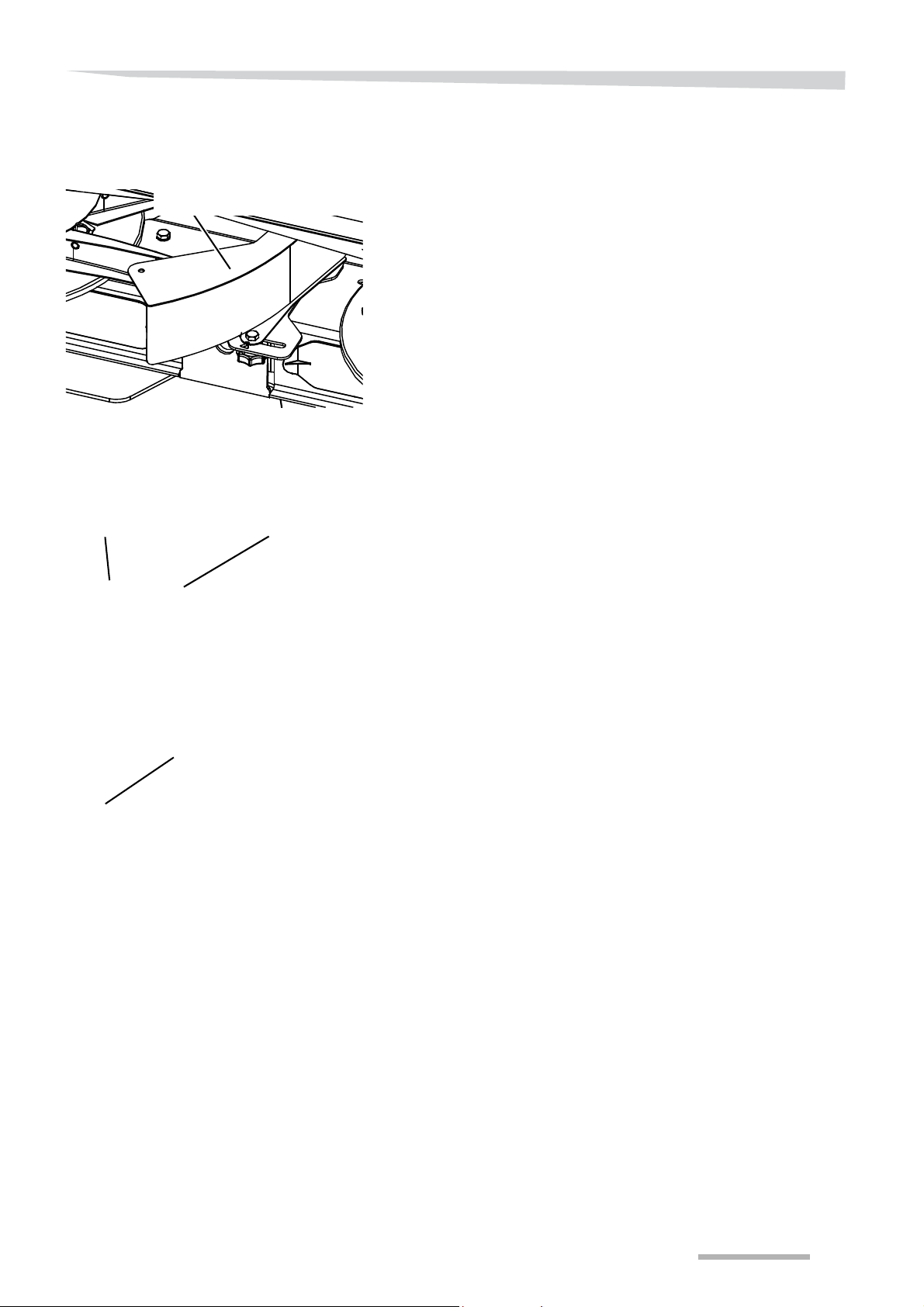
Before first use
Border spreading plate
Laminated box
Frame
Sensor
Border spreading
plate
Hydraulic border
spreading plate
Mount the support for the border spreading plate.
Mount the transport support for the border spreading plate, see
also the parts sheet.
Fit the frame to the machine, see also the parts sheet.
Fit the laminated boxes to the frame.
59
Page 60
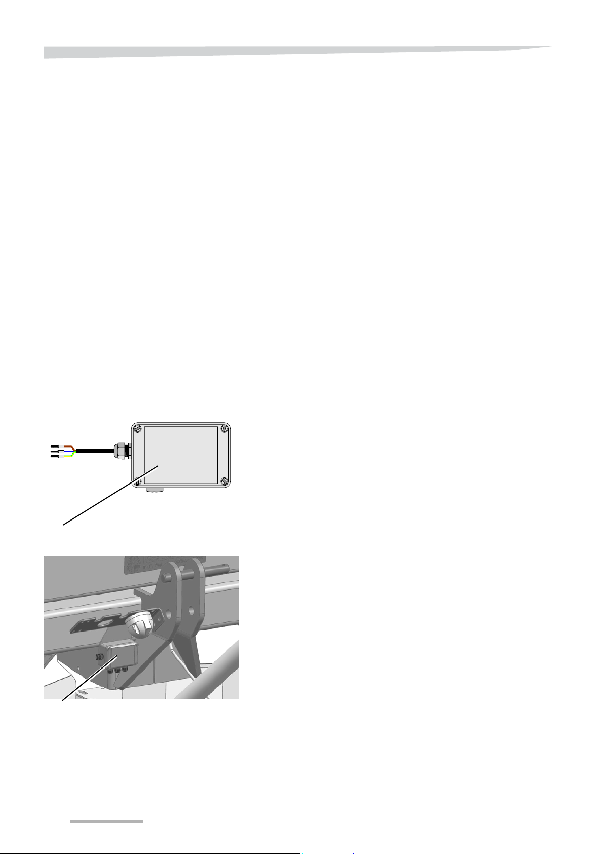
Before first use
Splitterbox
Splitterbox
Position indicator
A sensor is available with these accessories to be able to read in the
tractor cabin whether the TrimFlow(s) and/or the hydraulic border
spreading plate are in the working position.
A splitter box will be supplied if more than one of these accessories
are fitted.
3 sensors can be connected to the splitter box
Up to 2 sensors are connected to the RO-M EW.
This splitter box is connected to the machine electronics.
On the control box you can read whether the TrimFlow and the
hydraulic border spreading plate are in the working position.
The corresponding symbol will appear when the TrimFlow or the hydraulic border spreading plate is in the working position.
See »Sensor selection« on page 87,
60
Page 61
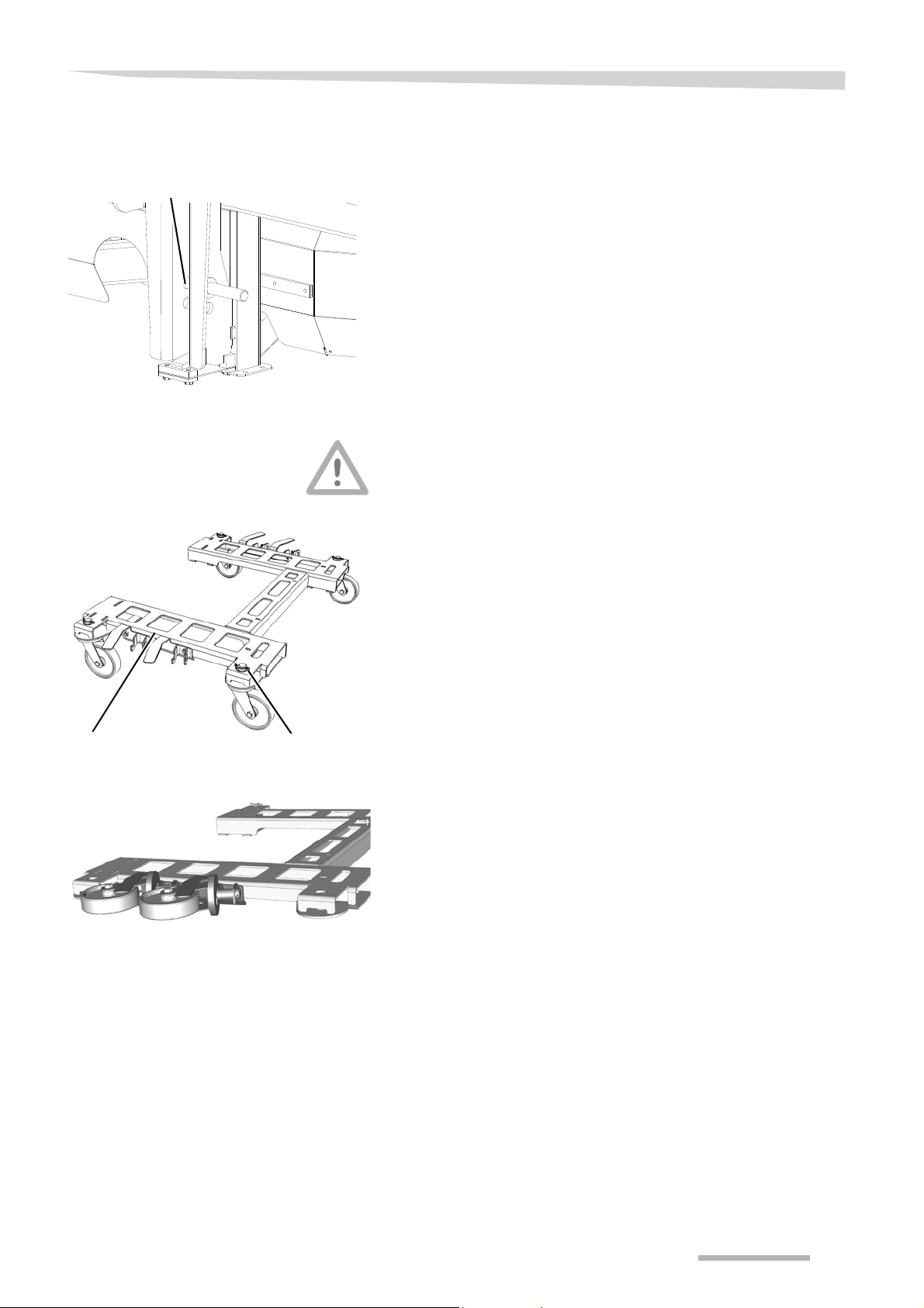
Before first use
High linkage pin position
Frame
Lock clip
High spreading setting
linkage pins
Parking wheels
You can put the linkage pin the high or low position, depending on the
height of the crops.
Only park with an empty hopper
Only park the machine on the parking wheels if the hopper is empty!
Parking with a filled hopper results in reduced stability. Moreover, the
wheels are not designed for heavy loads. The machine may be
damaged and physical injury may result.
A disconnected machine can easily be moved with the parking
wheels.
Raise the machine to working height.
Switch the tractor off, remove the key from the ignition and engage
the parking brake of the tractor.
Secure the machine by placing adequate supports.
Mount the frame on the machine as described in the spare parts
manual.
Secure the wheels with the lock clips.
Caster wheels may be placed on the side of the frame.
This prevents the crop from being damaged while spreading.
61
Page 62
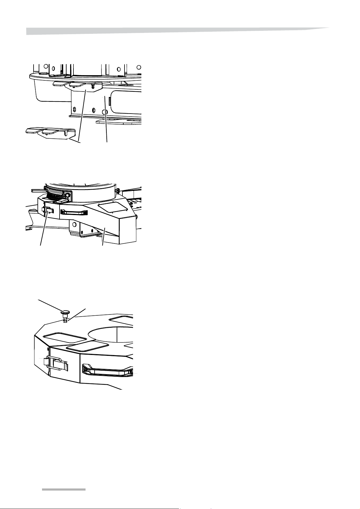
Before first use
Support for the calibration
container
Driving rod
Calibration container
S
Closing
Lock nut
S
Settings knob
Calibration container
The calibration container is used to control the dosing setting of the
machine.
The calibration container must be mounted on the left spreading disc
for the calibration test.
Remove the vanes.
Turn the nuts on the bolts with which the gearbox is mounted back
5 mm on the turning rod.
Push the bolts as far back as possible.
Hook the support behind the heads of the bolts.
Adjust the height of the support. The top end of the support must
be at the same height as the top end of the turning rod.
Fasten the nuts on the bolts again.
Note
Mount the support carefully so that the position of the gearbox does
not change.
Place the calibration container.
Fix the locks between the two halves.
Turn the other spreading disc by hand and listen if the spreading
disc in the calibration container is making contact with the
container.
Turn the lock nut upwards.
Turn the settings knob upwards or downwards until you can hear
that the spreading disc is no longer touching the calibration
container.
Turn the lock nut again.
62
Page 63
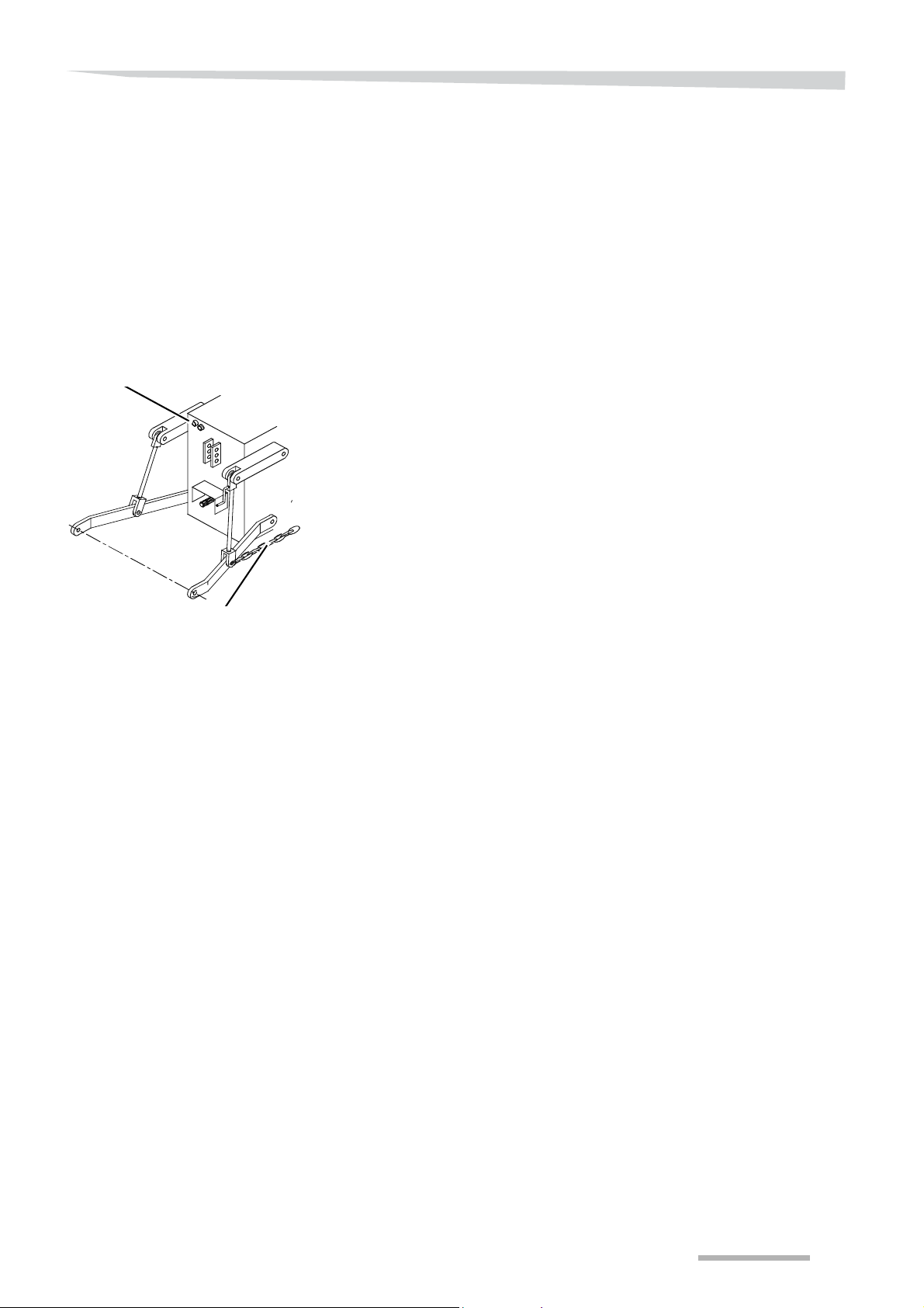
Before first use
Stabiliser chain
Valves
Tractor provisions
Power lift
Working with the machine requires a tractor that meets at least the
following requirements:
• Sufficient carrying and lifting capacity and engine power,
see section »Technical specifications« on page 44,
• correct type of properly adjustable power lift,
• adequate number of hydraulic valves,
See section »Required hydraulic valves« on page 64.
The tractor must be equipped with a Cat. II three-point power lift.
Easy control of top link and jaw adjustment is important. This system
is used for several machine settings.
The tractor must be equipped with stabiliser rods or chains for:
• preventing lateral machine movements and
• being able to select the correct position of the machine relative to
the tractor.
Electrical installation
Lighting
A trailer socket is required for the lights.
Control system
To operate the spreader, you need a connection for the ISOBUS plug.
See chapter »IsoMatch terminal on a NON-ISO tractor« on page
50.
Driving speed signal
A driving speed signal is needed in order for the control system to
function correctly.
See section »Driving speed signal« on page 51.
63
Page 64
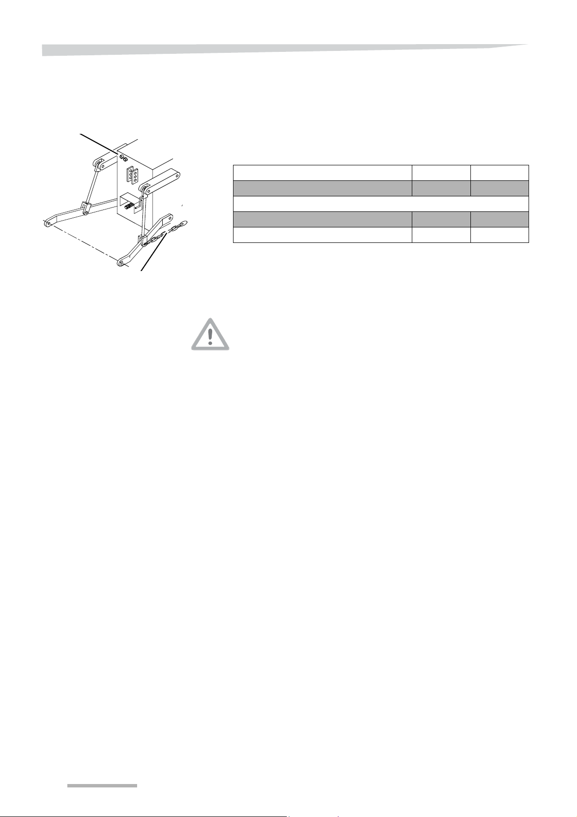
Before first use
Stabiliser chain
Valves
Hydraulic system of the
tractor
Mounting the
coupling shaft
T o operate the machine without accessories, the tractor must not have
hydraulic control valves.
1 or more single-acting hydraulic valves are required, depending on
the accessories selected.
Required hydraulic valves
Function Single Double
Standard spreader - Accessories
TrimFlow 1 -
Hydraulic border spreading plate 1 -
The coupling shaft provided is too long for mos t types of tractors
The coupling shaft must be cut to the correct length before connecting
it to the tractor. A coupling shaft that is too long could seriously
damage the machine and the tractor.
see the sec tio n » Checking the coupling shaft length« below, an d
the belo w sect ion »Shor te nin g th e coup ling sha ft «.
During lifting and lowering of the power lif t, the coupling shaf t requires
adequate space for
• sliding in and out,
• sufficient overlap between the profiled tubes when driving the
machine in the extreme operating angle of the coupling shaft.
64
Page 65
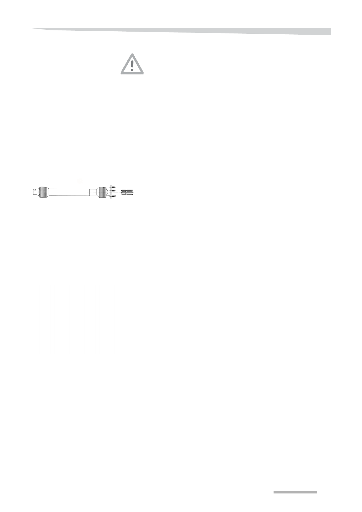
Before first use
Checking the
coupling shaft length
Put the machine on a supporting beam before moving in between
the tractor and machine
This will ensure that the machine cannot drop if the power lift should
inadvertently be operated while you are between the tractor and
machine. Without the support, a power lift that drops could wedge you
in, resulting in possible serious physical injury.
The length of the coupling shaft is checked and shortened after the
power lift is connected, but before the coupling shaft is connected.
Lift the machine with the power lift until the PTO shaft and the
machine drive axle are at the same height.
This is the shortest possible length between the two shafts.
Place the machine on a supporting beam.
Switch the tractor and the control box off, remove the key from the
ignition and engage the parking brake of the tractor.
Pull the coupling shaft apart into two halves.
Mount the loose tractor section of the coupling shaft to the tractor
PTO shaft.
Attach the loose machine component of the coupling shaft to the
drive axle of the machine.
Manually move the two coupling shaft halves next to each other.
Check the length and adjust it as described in the section below.
Shortening the coupling
shaft
The profiled tubes must overlap to the extent possible, with a minimum
of 150 mm.
The profiled tubes must however have at least 25 mm free clearance
at the outer edges when the tractor PTO shaft and the machine drive
axle are at the same height.
Shorten the two profiled tubes until 25 mm of clearance is
achieved.
Deburr both ends.
Clean the coupling shaft.
Shorten the protection sleeves by the same length.
Slide the coupling shaft halves into each other.
Connect the coupling shaft to the machine and tractor.
Lift the machine with the power lift to the highest operating position.
65
Page 66
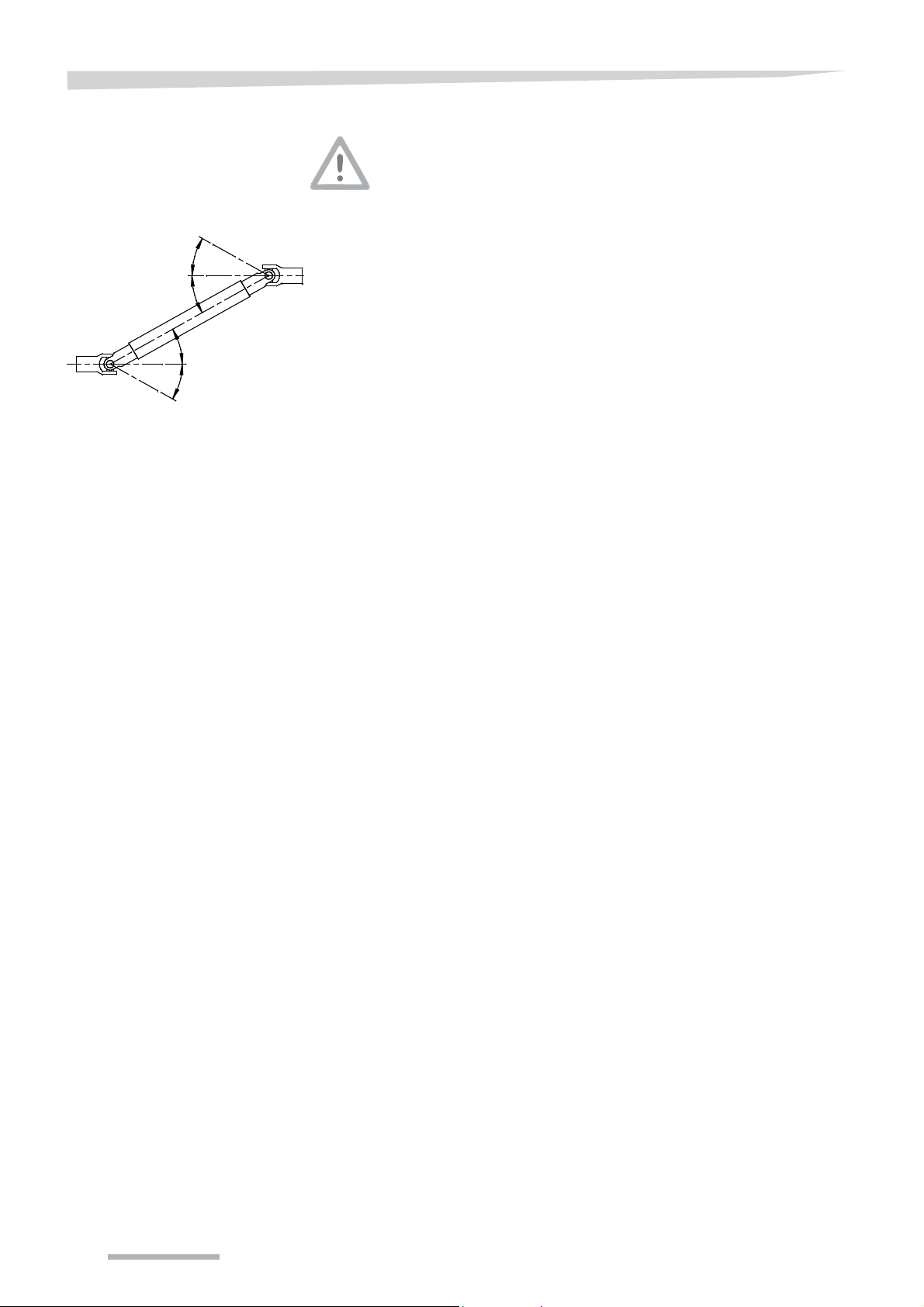
Before first use
max.30o
max.30o
max.30o
max.30o
Put the machine on a supporting beam before moving in between
the tractor and machine
This will ensure that the machine cannot drop if the power lift should
inadvertently be operated while you are between the tractor and
machine. Switch the tractor motor off. Without the support, a power lif t
that drops could wedge you in, resulting in possible serious physical
injury.
T
he maximum operating angle of the coupling shaft is 30° when lifted
°
and 30
when lowered.This is the maximum length between the PTO
shaft and the machine drive axle.
Place the machine on a supporting beam with the power lift at the
highest position.
Switch the tractor off and remove the keys from the ignition.
Engage the parking brake of the tractor.
°
Now check whether the furthest working angle is less than 30
.
Check that the overlap of the profiled tubes is still at least 150 mm.
Detach the tractor section.
Apply grease to the profiled tubes.
Attach the protection sleeves.
Slide the coupling shaft halves into each other.
Mount the coupling shaft on the machine.
66
Page 67

Before first use
Setting the safety clutch
There is a safety clutch on the machine side of the coupling shaft. This
safety clutch protects the machine against overloading.
First check the setting of the pressure springs in the safety clutch.
The spring length must be 26 mm.
A static calibration test can be performed with a torque wrench.
Set the torque wrench to 400 Nm.
Skidding should occur as soon as it is turned.
TIP
It is possible that the coupling needs to be “separated out” at a h igher
torque the First run.
Always mount the check chains of the protection sleeves
The check chains prevent the protection sleeves from rotating with the
coupling shaft.
Crop or pieces of clothing can be wound around rotating protection
sleeves and cause material damage and possibly severe physical
injury.
Mount the check chains to both outer edges of the coupling shaft
protective sleeves.
Mount the other ends of the chains to a fixed point of the tractor,
respectively the machine.
67
Page 68

Connecting to the tractor
Connecting to the tractor
Secure the operating elements
Ensure that parts such as ropes, hoses, etc., for remote actuation of
devices such as cylinders, are positioned in a way they never inadvertently release nor block them.
Unintentional movements can lead to serious injury.
Connecting and disconnecting safely
There are risks of injury involved in connecting and disconnecting the
machine. Work carefully by:
• engaging the parking brake of the tractor,
• securing a mobile machine from rolling away while being
connected,
• the machine should only be connected and disconnected from the
tractor on a firm, dry and flat surface so that the machine cannot tilt
and/or sink into the ground,
• removing other people from the direct vicinity of the tractor or the
machine,
• complying with the guidelines provided in this user’s manual,
• using a power lift that conforms with the regulations,
• never standing between the tractor and machine while the power
lift is operated externally while connecting or disconnecting the
machine,
• connecting the machine only to the points intended for that
purpose,
• connecting or disconnecting the machine only when the PTO sh aft
is off,
• checking the condition of the machine in order to e nsur e safe use
and transport.
Connecting or disconnecting the machine in an unsafe manner could
lead to serious personal injury and damage the machine.
Always mount the check chains of the protection sleeves
The check chains prevent the protection sleeves from rotating with the
coupling shaft. Crop or pieces of clothing can be wound around
rotating protection sleeves and cause material damage and possibly
severe physical injury.
68
Page 69
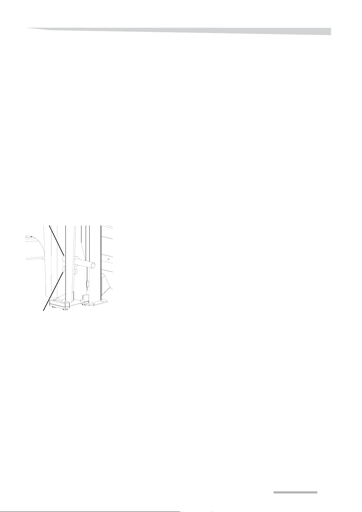
Connecting to the tractor
Linkage pin high
Linkage pin low
Check the coupling shaft
Check the following points before the PTO shaft is attached. Has the
coupling shaft:
• no damage, including the protection sleeves?
• are there sufficient lubricants as prescribed?
• is the prescribed overlap of the coupling shaft halves and
protection sleeves, both in transport and in operating position?
• Are the protection sleeves attached with chains to a fixed point to
guard against turning?
An unsafe or improperly mounted coupling shaft could lead to serious
or deadly injury.
If the coupling shaft does not comply with the points mentioned above,
it must be replaced before using the machine.
Selecting linkage pin
height
There is an option of two tension levels, depending on the height of
the crop. The lower hitch points are used if the maximum lif ting height
of the tractor is not sufficient to ensure that the spreading height is 75
cm above the crop.
The low hitch points are also used when fertilising high crops, which is
known as top dressing.
For further adjustments with top dressing, see
section »spreading height« on page 151.
69
Page 70
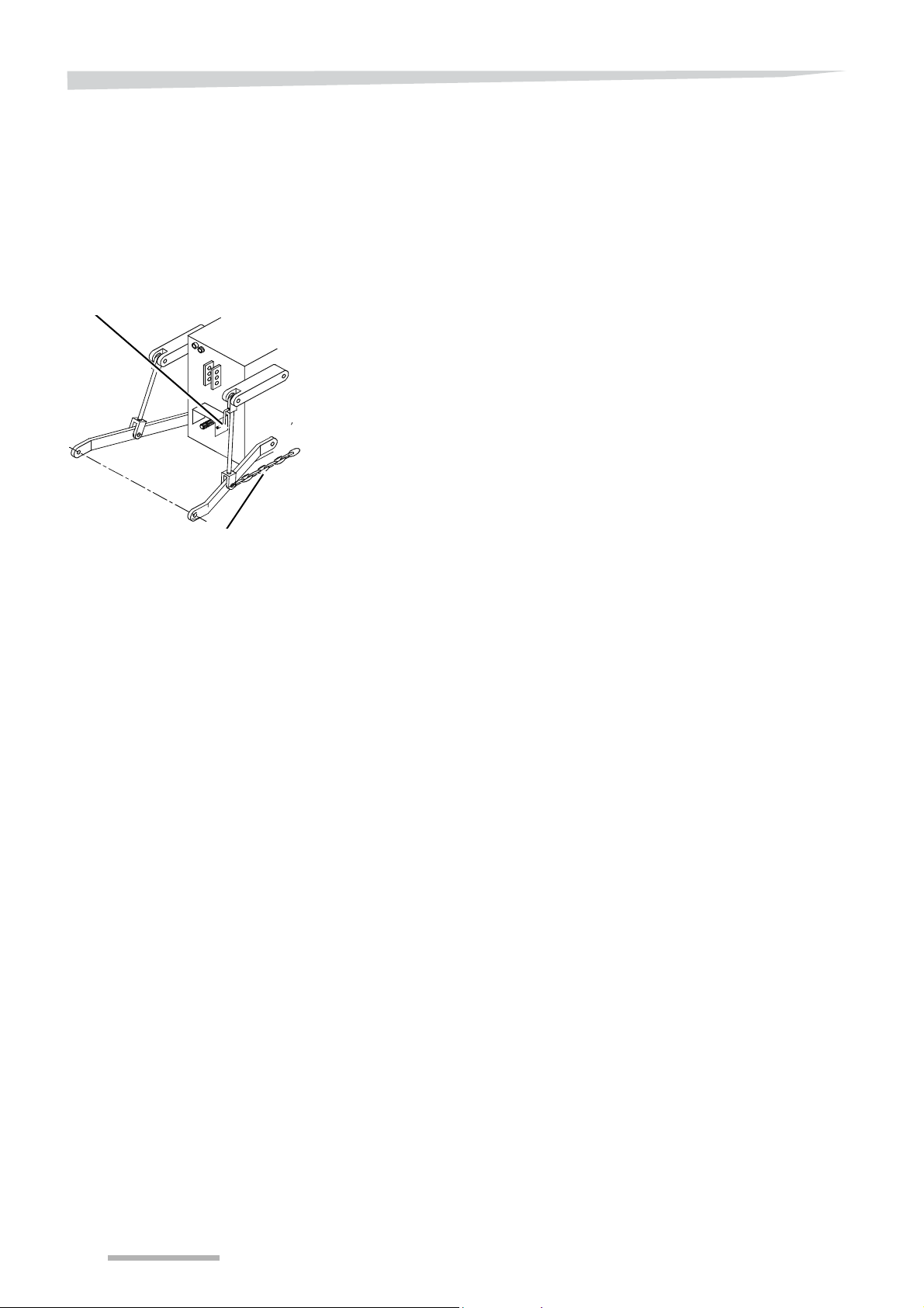
Connecting to the tractor
Lift rod adjustment
Stabiliser chain
Connecting the
machine
Preparation
The space between the spreader and the tractor is limited as far as
possible in order to keep the centre of gravity as closely to the tractor
as possible. This promotes stability and the road behaviour of the
tractor. As a result the coupling shaft, hydraulic hoses and electric
plugs must be connected first, followed by the power lift.
Move the tractor to the front of the spreader so that the catch hooks
of the power lift are around 200 mm from the spreader (the
maximum distance depends on the reach of the coupling shaft; the
halves must always overlap each other).
Take the pressure off the hydraulic system of the tractor.
Switch the tractor off, remove the key from the ignition and engage
the parking brake of the tractor.
Put the lower links of the tractor level with the machine linkage
pins.
Compensate for any height difference with the lift rod adjustment
of the power lift.
Adjust the stabiliser chains to make lateral movement of the lower
links impossible.
Mount the appropriate ball bearings to the linkage pins and the top.
Secure the linkage pins and top again.
Front power lift
Only connect the machine to the front power lift if:
• it has sufficient lifting power,
• it falls within the same fixing category as the machine,
• the minimum and maximum load of the front and rear weight would
not be exceeded,
• the tractor has a closed cabin and proper air filters (active carbon
filters).
70
Page 71
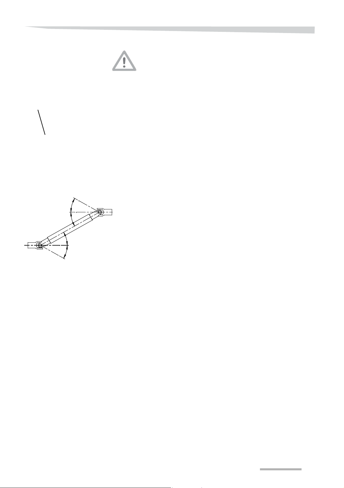
Connecting to the tractor
Safety plate
max.30o
max.30o
max.30o
max.30o
Connecting the
coupling shaft
The coupling shaft provided is too long for mos t types of tractors
The coupling shaft must be cut to the correct length before connecting
it to the tractor.
A coupling shaft that is too long could lead to serious damage to the
machine and the tractor.
See section »Checking the coupling shaft length« on page 65 and
section »Shortening the coupling shaft« on page 65.
Check the PTO shaft and the connector for dirt or damage.
Press the safety plate into the connector.
Slide the connector onto the PTO shaft.
Let go of the safety plate.
Check if the safety plate latches by moving the connector.
Attach the check chains to both outer edges of the coupling shaft
protection sleeves.
Mount the other ends of the chains to a fixed point of the tractor,
respectively the machine.
During lifting and lowering of the power lif t, the coupling shaf t requires
adequate space for
• sliding in and out,
• sufficient overlap between the profiled tubes when driving the
machine in the extreme operating angle of the coupling shaft.
Tip
°
The maximum operating angle of the coupling shaft is 30
°
and 30
PTO shaft of the tractor and the driving axle of the machine is reached
in this position. A greater working angle could damage the coupling
shaft.
when lowered. The maximum distance allowed between the
when lifted
71
Page 72
Connecting to the tractor
Connecting hydraulic
hoses
Checking the hydraulic
system
Colour codes of the hydraulic connections
Prevent malfunctions and errors in the controls by marking the
connectors with colours and the oil direction on the machine and the
tractor (+ and - or P and T or red and blue). Incorrect connection of the
hydraulic hose could lead to the functions working the other way
around (such as lifting instead of lowering). This could lead to
dangerous situations and could damage the crops.
If the machine is equipped with Trimflow (accessory) the hydraulic
hose must be connected for operation.
Check the hydraulic quick coupling on the tractor for dirt. Clean if
necessary.
Remove the hose from the hose coupling support and check the
quick coupling for dirt. Clean if necessary.
Connect the quick coupling.
Place the hose so that it would not pinch or damage.
Regularly inspect th e hyd r au lic syst em .
See also section »Checking the hydraulic system« on page 187.
High pressure in the hydraulic system
Keep your distance from the hydraulics during inspecting and test
running. The hydraulic system is under high pressure. Oil jet s or hoses
that snap back may cause serious physical injury and fire due to the
prevailing pressure and temperature. Liquid under high pressure can
easily penetrate skin and clothes and may cause severe injuries. In
the event of injury, contact your physician immediately!
Connecting electric
plugs
Regularly inspect th e hyd r au lic syst em .
See also section »Checking the hydraulic system« on page 187.
Connect electric plugs safely
Connect the electric plugs correctly. Conduct the electric plugs and
cables in such a way that they are not pinched or damaged. Use only
the intended electric connection. Never use a cigarette lighter.
Check the plugs and the connections on the tractor for dirt. Clean
if necessary.
Connect the electric plug(s) for the lights.
Connect the ISOBUS communication plug.
Connect the control box
• by connecting an ISO plug, which has both CAN plugs on the
one side of the cable, to the back of the control box and the
CAN plug on the other side of the cable to the connection on the
ISOBUS network of the tractor,
• Remove the CAN plug of the tractor ECU from the control box
if the tractor is equipped with a tractor ECU.
Place the cables so that they are not pinched during work activities.
72
Page 73

Connecting to the tractor
Connecting the
power lift
Check the decoupling ropes of the quick coupling
The decoupling ropes must never be tense and must provide su fficient
freedom for movement, even with the power lift in the lowest position,
as it could otherwise accidentally disconnect the quick coupling.
Accidental disconnection could damage the machine and may result
in personal injury.
Start the tractor.
Reverse carefully so that the catch hooks of the lower links are
exactly under the ball bearings.
Open the quick coupling of the catch hooks with the release ropes.
Engage the power lift until the ball bearings are correctly located in
the catch hooks and close the quick coupling.
Check if the catch hooks have locked correctly by lowering the
power lift carefully.
Turn the top link to the appropriate length and secure if possible.
Open the quick coupling of the catch hook with the release rope.
Let the catch hook fall over the ball bearing at the top and close the
quick coupling.
Check if the catch hook is correctly secured by pushing and pulling
it.
73
Page 74

Connecting to the tractor
Checking and setting the
machine
Always check the machine after connection and set it horizontal if
required.
Lift the spreader until it is lifted from the ground or ramp.
Switch the tractor and the control box off, remove the key from the
ignition and engage the parking brake of the tractor.
Check the locking system of the catch hooks of the lower links and
the top link.
Make sure that the electric cables and hydraulic hoses do not get
jammed. Lead them or tie them up in order to prevent dangerous
situations. Make sure that there is sufficient space for movement
when lifting or lowering the machine.
Adjust the machine so that it is level with the lift rod adjustment.
Turn the top link until the machine is standing horizontally.
Lock the top link when that is possible.
74
Page 75
System settings
Keyboard popup
Main screen with IsoMatch keyboard
System settings
Differences in operation
For a correct control system operation, it is necessary to set and
calibre the spreader before first use or after an alteration to the
machine, for example after fitting extra accessories. Moreover, you
can enter a number of system settings to increase your ease of use.
The method of working and display when using the IsoMatch or Tellus
control box (accessory) is described in this user manual.
If your tractor has an ISOBUS communication system with an
independent terminal which you use to operate the spreader, the
version of the screens and key functions may deviate slightly. The
procedure to enter values or changing settings can be different.
Differences in screen layout and interchangeable keys
The Focus II and the ISO-tractor terminal may have 5 or 6 buttons left
or right of the screen.In that case, you switch between the function
keys with a switch key. The operation of this terminal is described in
the user 's ma nu al of the tr act or or co ntr o l box.
Differences in operation of fixed buttons (Tellus, Focus II),
touchscreen and popup numeric keyboard (IsoMatch)
Keys of the Tellus control box are assumed in the description. The
IsoMatch uses a touchscreen to execute all settings. If you touch a
value on the screen in order to change it, a nume ric keyboard appears
to execute it immediately.
Entering system
settings
Certain functions, such as date, time, communication with an exter nal
system, etc., must be set in the operating system of the control box.
Refer to th e us er 's manual of the tractor or the control box.
The system settings are needed for the good operation of the control
system. Moreover , this enables you to enter your user preferences, fo r
example, for alarm signals.
Link the machine up as described in
chapter »Connecting to the tractor« from page 68.
Check that the machine is clean and all accessories are fitted.
Position the spreader horizontally and vertically, by means of the
top link and the lift rod adjustment.
Start the tractor and drive to a place with a firm, horizontal base.
Engage the parking brake of the tractor, but do not switch off the
engine.
Switch the control box on .
The main screen of the spreader will appear on the control box after a
few seconds.
75
Page 76
System settings
S
Hopper alarm
S
Alarm level
S
Numeric keyboard
100
Hopper alarm
This setting enables you to let an alarm signal appear on the main
screen as soon as the hopper content goes below a preset level.
Press the key switch in the main screen to go to the ‘Curve
Calibration’ screen.
Press on the alarm level value on the IsoMatch screen.
The popup numeric keyboard with the alarm level to be changed
appears on the screen.
Key in the new value on the numeric keyboard.
The new value is on the screen of the keyboard.
Confirm it or cancel it with the OK or cancel key.
The new value is on the Curve Calibration screen.
76
Page 77
System settings
S
TrimFlow position
S
Actual weight in the hopper
S
Simulation speed
signal
S
Deviation reference
sensor
S
Driving speed signal from Starguide 3/4
TrimFlow position
Driving speed signal
If the spreader is equipped with a Trimflow, the position, working
position or transport mode can be displayed on the main screen. The
position is poorly visible from the tractor. By means of the display on
the main screen, you should make fewer sp reading errors ca used by
incorrect Trimflow positioning. In working position, the Trimflow
symbol appears on the main screen. In transport position, the symbol
does not appear.
Press on the display on/off area of the TrimFlow position.
The tick appears or disappears as per the TrimFlow position on the
screen.
The change is saved immediately.
The remaining system settings are in the ‘Settings’ screen.
Press the scroll key to go from the ‘Curve Calibration’ to the
‘Settings’ screen.
You must enter the source of the driving speed signal on the top line.
By means of the signal, the spreader adapts the d osing setting so that
the application rate remains the same when the driving speed
changes.
The driving speed signal can come from:
• Simulation speed (Manual, in the Settings screen)
• the tractor radar, (ISO Radar)
• the wheel sensor connected to the tractor ECU, (ISO Wheel)
• Starguide 3/4 (Starguide 3/4)
• the GPS receiver. (GPS J1939)
In the input field for the driving speed signal source, yo u can choose
from the following:
• ‘Manual’, if there is no speed measurement at all. The control
system is then dealing with a fixed, input value and therefore does
not correct for changes in driving speed! You can en te r the
simulated driving speed on the main screen,
• 'ISO radar'; if the signal comes from the tractor electronic unit or
radar,
• ‘ISO wheel’, if the signal comes from a speedometer connected to
the tractor ECU,
• Starguide 3/4 where Starguide 3/4 is connected.
• ‘GPS J1939’, if the signal comes from the GPS receiver. Reception
of an external signal must of course be connected,
See section »Set ISOBUS communication« on page 88.
77
Page 78
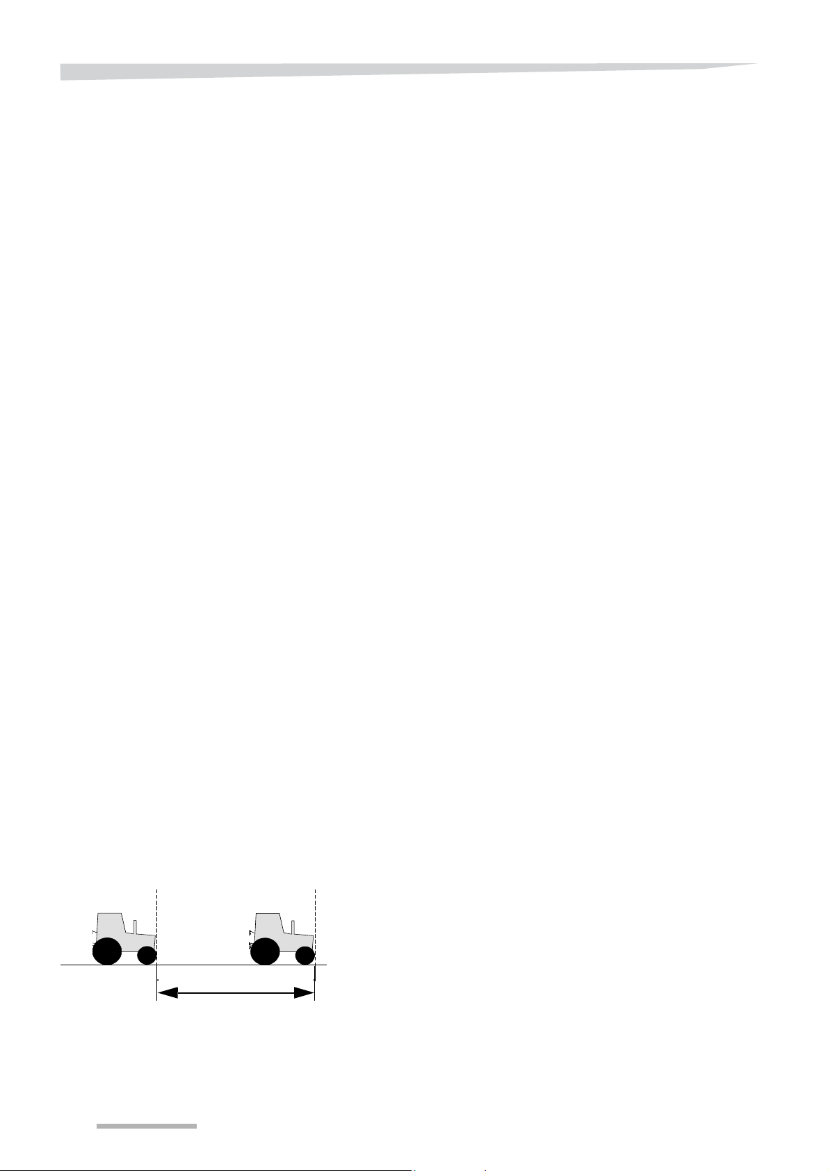
System settings
100 metres
Calibrating driving
speed sensor
The control system corrects the dosing as the driving speed chang es.
An accurate driving speed signal is therefore essential.
Perform calibration of the driving speed:
• before using the machine for the first time,
• after adjusting the measuring system for driving speed, e.g.
after a sensor is replaced,
• when other tyres or wheels are being used,
• when used under extreme circumstances, e.g. with excessive
wheel slip.
• in situations where one or more of the following causes for
deviations are present.
Deviations in driving speed measurement can be caused by:
• engaging or disengaging front-wheel drive,
• changing soil composition,
• wheel slip,
• more or less full hopper than during calibration,
• variation in inflation pressure (changes the wheel diameter),
• tyre wear,
• working on slopes.
Preparation
Operation
Some of the causes of deviations mentioned do not apply to
speed measurement on the wheel of a trailed machine.
All readings regarding skidding, driving tyre pressure, etc. are taken
from the measured wheel.
Take all precautions necessary on the tractor and on the machine,
see
section »Tractor provisions« from page 63.
Connect the machine,
See section »Connecting to the tractor« on page 68.
Fill the hopper to half,
Check the settings in the control system with regards to driving
speed measurement and change as required,
See section »Driving speed signal« on page 77 51and
Check the inflation pressure and ensure that it is at the required
levels.
Drive to the site that you are going to spread.
Perform calibration for the driving speed as far as possible under
similar circumstances under which work normally takes place.
• Carry out the calibration on the site that you are going to work on
• The machine connected to the tractor and half filled,
• and drive with the desired working speed.
Disengage the front wheel drive, unless it will also be engaged
while working.
Carefully measure a distance of 100 metres and mark the start and
end points, e.g. with pickets.
Place a marker on the tractor at the starting point, e.g. in the middle
of the front wheel.
78
Page 79

System settings
TIPYou will find the working method for calibrating driving speed in the
user's manual of the tractor, IsoMatch, Tellus-/ Focus II con trol box,
tractor ECU or wheel sensor.
Damping of the driving
speed display
If the driving speed display is not stable or if it follows the change too
slowly, this needs to be corrected.
Adjust the damping factor, 50% of the factory setting to where the
display would be correct.
Also refer to the manual that comes with your control box.
79
Page 80
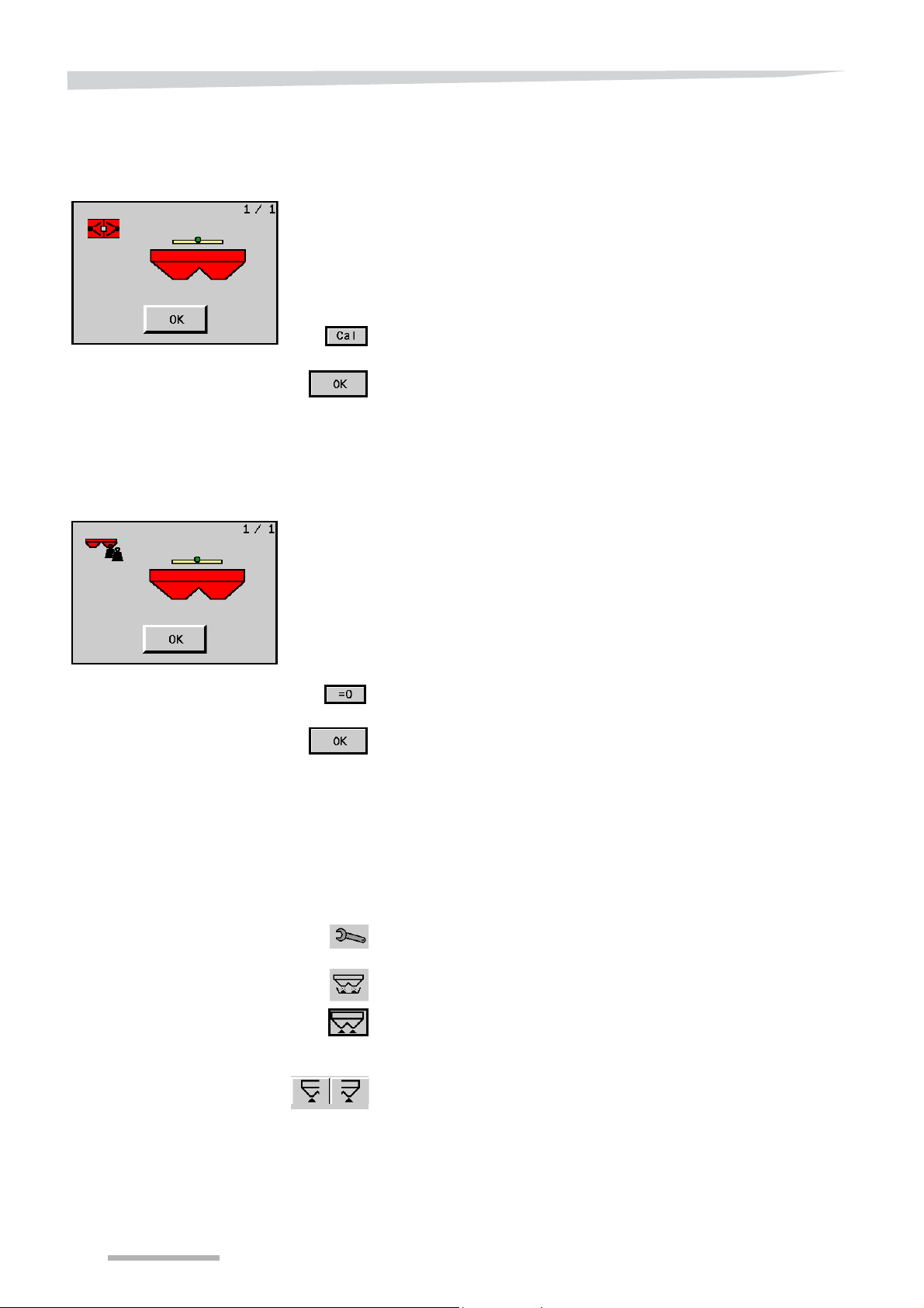
System settings
Deviation of the
reference sensor
Actual weight in the
hopper
During calibration of the reference sensor , the outgoing signal is set at
'0'. As a result of changing circumstances, for example temperature
differences, or in the event of wear and tear, the reference sensor can
produce a deviating signal after some time. If the signal value is
greater than 25 for a machine placed horizontally and vertically, the
reference sensor must be recalibrated.
Place the tractor on a horizontal base.
Empty the hopper, clean the machine and wait for it to dry.
Position the spreader horizontally and vertically, by means of the
top link and the lift rod adjustment.
Press on the ‘Cal’ button.
The reference sensor is calibrated anew.
Close with "OK".
The field shows you the actual weight of the hopper content. If you
have emptied the hopper but this value is different to ‘0’, you can
overwrite it. Only use this function for small deviations. For large
deviations and especially for modifications to the machine, for
example after assembly or disassembly of a hopper extension or
hopper cover, you must recalibrate the hopper weight.
See section »Hopper weight calibration« on page 92.
Empty the hopper
Place the tractor on a horizontal base.
Empty the hopper, clean the machine and wait for it to dry.
Set the machine horizontally and vertically by means of the top link
and the lift rod adjustment.
Press on the ‘= 0’ button.
Press the OK key to set the current weight as the hopper's basic
weight.
To remove residual fertiliser from the hopper, a 'Empty hopper' function is present.
Set the fine application lever to the normal dosing setting.
Start the tractor and engage the control box.
Press the key switch in the main screen to go to the ‘Curve Calibra-
tion’ screen.
Press the empty hopper key to go to the screen for emptying the
hopper.
Press the 'empty hopper' button in order to empty the hopper on
both sides simultaneously.
Press the OK key to stop emptying the hopper.
The left and right actuators can be operated separately with the left
and right 'Empty hopper' buttons.
80
Page 81
System settings
S
Supply voltage alarm
S
Spreading disc rpm alarm
S
Alarm lubrication
Supply voltage alarm
Spreading disc rpm
alarm
For good control system functioning, the voltage on the feeder cable
must be at least 10.5 volts. Switching on the alarm causes a warning
to appear on the screen if the supply voltage is lower than a value that
you have preset.
Press the field of the alarm on/off for supply voltage.
If you switch on the alarm (ticked), you can then enter the minimum
voltage value in the input field.
Press on the display of the minimum supply voltage.
The popup numeric keyboard with the value to be changed appears
on the screen.
Key in the new value on the numeric keyboard.
The new value is on the screen of the keyboard.
Confirm it or cancel it with the OK or cancel key.
The new value appears after confirmation on the screen.
If you have commanded the control system to start spreading, you could
have forgotten to switch on the PTO shaft. Then you waste fertiliser
and time. Switching on this alarm ensures that a warning will appear
on the screen at once should you start spreading with the stationary
spreading discs.
Press the field of the alarm spreading disc rpm on/off.
Alarm lubrication
I
NDICATION
The alarm is engaged (ticked).
The alarm only checks that the spreading discs are stationary; not if
you have set the correct rpm.
This alarm gives a warning every 8 hours that it is time to lubricate the
machine.
Press the alarm field on/off for lubricating.
81
Page 82
System settings
S
Over and under
dosing unit
S
calibration test
side
S
Selection for Metric / Imperial
Over and under dosing
unit
calibration test side
While spreading, you can manually (one-sided) o ver- or underdose on
the main screen. By pressing 1 time on the plus key or minus key
beside the screen, you can adjust the application rate by a percentage
of the application rate or a preset number of kilograms. You can enter
the percentage or number of kilograms on the main screen.
Press on the field of your choice:
• Percentage
• or kg.
The choice is engaged (ticked).
You can perform the calibration test on the left or right spreading disc.
The control system must know what side you want to do the calibration
test on to open the correct dosing unit.
See section »Manually entered application rate« on page 119.
Press on the field of your choice:
• Right side
Settings screen (2)
Selection for Metric /
Imperial
• or left side.
The choice is engaged (ticked).
TIPIf your machine is equipped with a TrimFlow, it is recommended that
you choose the left side for the calibration test. There you will have
more space to move, for example to assemble or disassemble the
vanes and the calibration container.
Press the scroll key to go from the "Settings" screen to the second
‘Settings’ screen.
Here you can select either the metric or the imperial display.
Go to the next Settings screen to switch to Imperial values.
Press on the field of your choice:
• Metric
• or Imperial.
The choice is engaged (ticked).
82
Page 83
Settings behind pin code
S
Input screen of pin code
S
Numeric keyboard
5
Press the scroll key to go to the next 'Settings' screen. The PIN
From the main screen:
Press the key switch on the main screen; you will now go to the
Press the scroll key twice to go from the ‘Curve Calibration’ to the
Press on the input field with 0.
The popup numeric keyboard with the n umber to be changed appears
on the screen.
Key in the new value on the numeric keyboard
the PIN code is 5
System settings
screen appears. The remaining screens are present behin d the pin
code.
'Curve Calibration' screen.
‘PIN’ screen.
Settings screen (3)
The new value is on the screen of the keyboard.
Press the OK key to confirm the PIN code
or cancel with the cancel key.
The 'Settings 3' screen will now appear.
You can select the following setting and/or option here:
• Auto-calibration limit on/off and limit value of automatic calibration
• Selection of the weighing system, RO-M EW 1 or RO-EDW 4
weighing sensors. The option for 3 sensors is not used.
• Auto-calibration setting for large, medium-sized or small field
• Gored spreading on/off
• TrimFlow and hydraulic border spreading plate setting
• Weighing system filter settings
83
Page 84
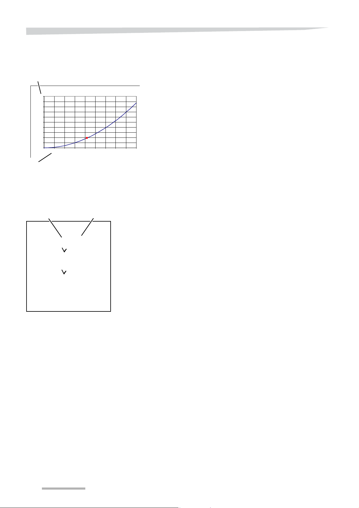
System settings
0,0
50,0
100,0
150,0
200,0
250,0
300,0
350,0
400,0
450,0
500,0
0 102030405060708090
Flow rate (kg/min)
Dosing setting
S
Limit
S
Limit On/Off
15
Automatic calibration
limit
Auto-calibration with external control of the application rate
In some cases, it is advisable to switch the automatic calibration off
temporarily. For example, if you are spreading by means of an
external signal. It can also happen that the dosing unit is closed at any
time while the spreader is connected. If the spreader automatically
recalibrates at that time, it might determine a partially incorrect
discharge curve. If the external system drives the dosing units open
shortly thereafter, the application rate will deviate from the desired
value because in the discharge curve, the flowrate calculated for the
highly deviant dosing setting is not totally correct.
See also section »The ISO control system« on page 30.
You can prevent similar errors by entering a flowrate limit in the
'Settings 3' screen. Below this flowrate, the control system will perform
automatic calibration but will continue to use the last set discharge
curve.
Setting calibration limit on or off
Press the option field calibration limit on/off.
The tick indicates that the automatic calibration is switched off
below the set limit.
84
Setting calibration limit
If you switch the limit on, you can then enter in the input field the flow
rate value under which automatic calibration is switched off.
Press on the input field of the flowrate.
The popup keyboard displays the old value.
Enter the desired flowrate.
The new value is on the screen of the keyboard.
Press the OK key to confirm the value
or cancel with the cancel key.
Automatic calibration stops below the new flo wrate of 15 kg/min.
Page 85
System settings
S
Choice of parcel size with auto-calibra-
S
Gored spreading Yes/No
Adapting auto-calibration to
field size
Gored spreading is not/is
possible
Perform auto-calibration more often on smaller parcels
If you predominantly spread over larger parcels, the factory setting of
auto-calibration is sufficient. If once per minute or 75 kg is not sufficient, choose the medium-sized or small parcel setting.
Press the current option field for field size:
Press on the checkbox of your choice.
Spreading subsequently in case of parcel bounda rie s which are
not right-angled
Sometimes you cannot spread across the full working width during
passes. A spreader with the option of adjusting the working width automatically via a GPS can perform gored spreading. You can then
spread without compromising on the quality of the spreading.
This option is already available in your operating software. Not every
spreader is suitable for this.
• Large parcel
• Mid-sized parcel
• Small parcel
TIPIf the spreader is equipped with the GEOspread system, it is checked
as factory setting.
N
OTE
Use this function only if your spreader is suitable for it.
With
• GEOspread dosing,
• activated GEOspread and GEOcontrol license,
• GPS signal.
Press the option field gored spreading on/off.
I
NDICATION
Switch the TC functions on as well.
See section »Set ISOBUS communication« on page 88.
85
Page 86

System settings
S
Display of gored spreading
Display of gored spreading in the
main screen
The changed working width, to the left and/or right, is displayed
graphically on the main screen along with numerical values, with the
gored spreading function turned on.
86
Page 87
Sensor selection
S
Sensors selection
S
Sensors selection
S
Filter
System settings
Depending on the type of accessory you select:
none
Hydraulic border spreading plate (Center)
TrimFlow right(Right)
TrimFlow Left
Multiple accessories through splitter box(Sensor box).
See »Position indicator« on page 60,
Weighing system
filter
While spreading on very hilly terrain, the weight in the main screen
may sometimes vary.
You can select the weighing system filter in order to counter this
variation.
Press the filter field on/off.
choose a value between 5 and 15. The weighing system now
operates with an average of the number of values given.
87
Page 88
System settings
S
Spreader control On/Off
S
Receiving an external
application rate
S
Memory cache
internal / external
S
Task controller
On/Off
Set ISOBUS communication
Setting communication with
an external system
The spreader can be driven by an external signal, which could for
instance be transmitted by a GPS receiver , nitrogen sensor or memory
card. To assign a controlling function to the external signal, it must be
received in the 'Task Controller' screen.
Acceptance of an external signal and the correct form of communication must be checked and adjusted as required.
Also refer to the user manual of the tractor or control box.
Go from one of the settings screens to the ISOBUS communication
See »Menu structure« on page 42.
Scroll to the 'TC Config & License' screen.
In this screen, you can control and/or modify the settings of the Task
controller:
If you return the spreading details to the source of th e external signa l,
you cannot reach the system's field registration. Dual storage is not
possible.
See then section »Variable, externally driven application rate« on
menu.
• Task controller on / off
• 2 options of memory cache are:
• Reception of an external signal, whereby spreading details are
stored in the parcel registration of the control system
(internal).This setting is activated when a "tick" is visible in the
input field.
• Reception of an external signal, in which the spreading details
are sent back to the source of the external signal, for example
a memory card. This setting is activated when the “+E” sign
page 126 for further details.
88
• Receipt of an external application rate on / off.
With this option, you allow the set application rate to be modified by
the externally defined application rate.
• Spreader control On/Off
You can turn the Spreader control function on or off here with the
spreader intended for the purpose.
The lowest part of the screen displays the setting of the working width
distribution before spreading with Spreader control:
• The maximum number of sections is 24.
• The standard weighing spreader has 2 sections (L/R lockable).
• Each section has a working width of 12 metres here.
Page 89
System settings
S
Webshop
Identification of the
spreader control
S
Counter for time of
use of free software
S
Spreader control
On/Off
S
S
Input field for licence code
S
Maximum number of sections
S
TC Fni
Using the Spreader control
software
TIPThis counter starts as soon as you have activated the software!
TIPPurchase the software licence in good time!
N
OTE
First 25 hours of use free
If the spreader is capable of
• being driven by an external acceptance rate
• or is equipped as a 'GEOspread' machine
this can be used for 25 hours free of cost.
A counter indicates how long you can still use the software free of cost
.
Time of use alert
You get the first alert that the free time of use will expire after some
time. The remaining free time of use is also displayed upon each startup of the system.
You need to purchase the licence via the IsoMatch webshop in good
time in order to be able to continue working without disturbance after
the free time of use has expired.
• The spreader must be capable of working with the Spreader
control software!
• You also need to provide the location and control of the working
width to your tractor via the ISOBUS. This can also be done by
building another module in the IsoMatch or tractor.
See the options »Accessories« on page 200 or ask your dealer
about them.
Purchasing the
software licence
Read the product identification code in the TC config & License
screen and write it down.
Go to www.isomatchshop.com webshop.
You will see the possible software packages which you can purchase
via the IsoMatch terminal in the webshop.
Enter the licence code that you have received.
You can now continue working with the spreader software.
TC Sections indicates the maximum number of sections.
TC FnI represents the Check Digit for the connection between
spreader and GEOcontrol, it must be the same as the digit in the
settings screen of GEOcontrol.
The actual number of sections and working widths per section is given
in the section mapping, where the left digit indicates the outer
sections and the right digit the two centre-most sections.
89
Page 90
System settings
S
Selector for mounted machines
Setting machine data
Mounted machine
The position of the signal receiver and the place where the machine
works effectively are mostly dif ferent. To allow the machine to operate
correctly in the right place, you must run the following settings:
Go from one of the settings screens to the ISOBUS communication
menu.
See »Menu structure« on page 42.
Scroll to the "TC Implement Settings" screen.
In this screen, you can control and/or modify the settings of the
vehicle:
• Mounted machine
In this screen, you can run the following settings:
• Offset connecting point with respect to the tractor track (A)
• Distance from signal receiver to hard spreading discs (B)
The distance from signal receiver to spreading discs plus 1/3 x
working width. The control system can now calculate the correct
speed reduction for subsequent spreading on the headland and
during gored spreading.
With control by means of an external signal, it is often better to switch
off the automatic calibration when the dosing setting goes below a
specific value.
See section »Automatic calibration limit« on page 84.
90
Page 91
or
S
Selector for drawn machine
S
Correction time
System settings
Trailed machine
Correction time
• Trailed machine
In this screen, you can run the following settings:
• Offset connecting point with respect to the tractor track (A)
• Distance from signal receiver to hard wheel axle (C)
• Distance from hard wheel axle to hard spreading discs (B)
The distance from signal receiver to spreading discs plus 1/3 x
working width. The control system can now calculate the correct
speed reduction for subsequent spreading on the headland and
during gored spreading.
Correction time for opening and closing the dosing; the time can be
adjusted, shorter for a low application rate and longer for a high
application rate.
91
Page 92
System settings
S
Right actuator
S
Left actuator
S
Spreader empty weight
Spreader calibration
Actuators calibration
It is very important that the weighcells and actuators be calibrated correctly for the spreader to function properly. Your spreader is supplied
calibrated. The actuators need only be recalibrated if one or both of
them are replaced.
Incorrect calibration will result in a deviating application rate and consequent damage to the crop. For this reason, the sections in which
you carry out calibration are secured with a PIN code.
From the main screen:
Press the key switch on the main screen; you will now go to the
'Curve Calibration' screen.
Using the scroll key, go from the 'Curve calibration' to the 'PIN'
screen.
Press on the input field.
The popup keyboard appears on the screen.
Key in the PIN code; the code is 5.
Press the OK key to confirm the PIN code
or cancel with the cancel key.
The ‘Settings’ screen will now appear.
Actuator calibration is completely automatic. After calibration, the minimum (‘min’) and maximum (‘max’) values must be 10 and 1015.
The highest value concerns the left actuator, the lowest value the right
actuator.
Hopper weight calibration
From the ‘Settings’ screen:
Press the scroll key to go to the ‘Hopper&Act Calibration’ screen.
Press on the 'Cal' button of the actuator that you wish to calibrate.
Wait until calibration is complete and the new values appear on the
screen.
Indication
For safety reasons, you can stop the actuators at any time during calibration by pressing the OK key. You must th en restart calibration.
The weighcells weigh the hopper's mass, including accessories fitted
to the hopper and the hopper content. The control system must know
the weight of the hopper content in order to, for example, to calculate
how many more hectares you can sprea d before the hoppe r is empty.
Or to sound the hopper alarm at the right time. For that reason, the
system memory must contain the we ight of the empty h opp er a nd the
accessories fitted to the hopper, such as the hopper extensions and
hopper cover. You can see the saved values on the ‘Hopper&Act calibration' screen.
92
Page 93
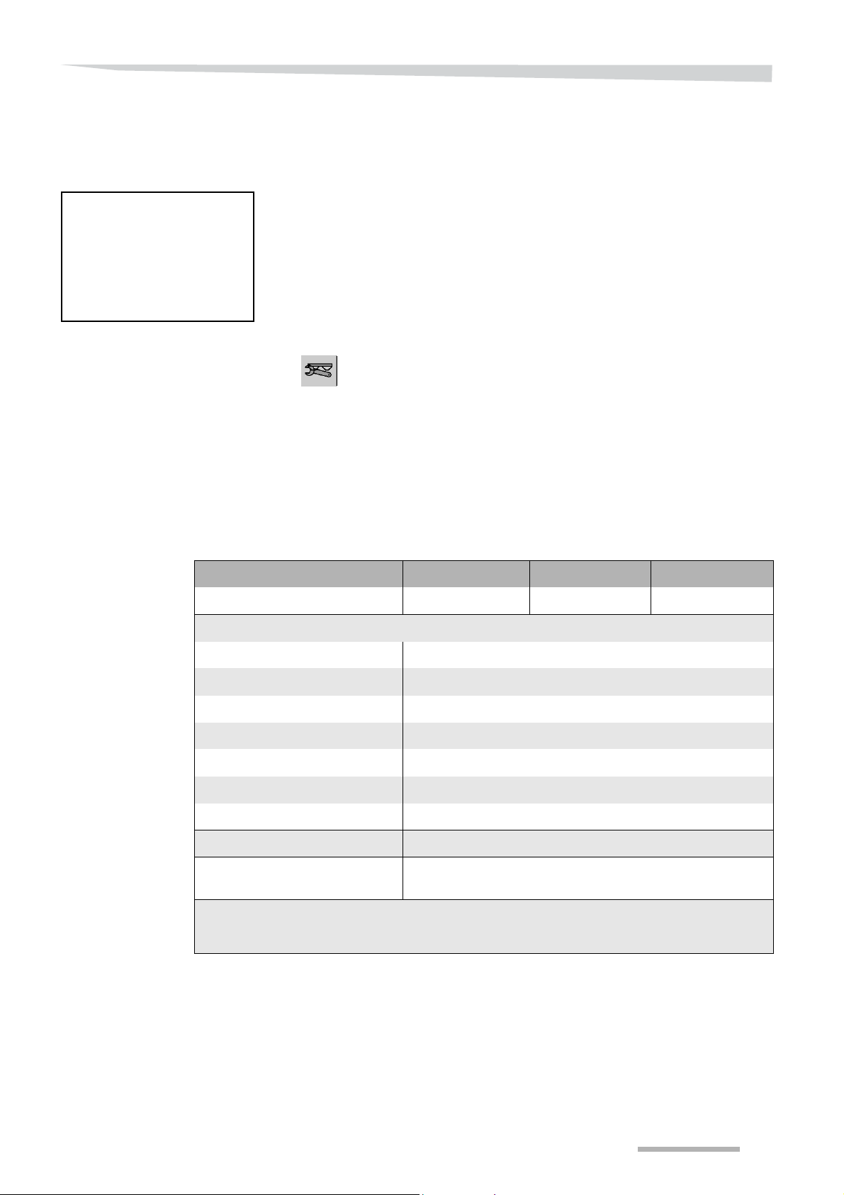
System settings
Include the weight of all accessories
Whenever you fit or remove spreader accessories, you must
recalibrate the spreader weight each time.
You must also do this when you have emptied the hopper but the
control system indicates that a few kilograms of fertiliser are still in the
hopper.
Empty the hopper, clean the machine and wait for it to dry.
Position the spreader horizontally and vertically, by means of the
top link and the lift rod adjustment.
Place the tractor on a horizontal base.
From the ’Hopper&Act Calibration’ screen:
Press the hopper calibration key to go to the hopper calibration
screens.
Press on the input field.
The popup keyboard appears on the screen.
Enter the actual value such as it is displayed in the below table.
The spreader weights in the chart are:
• including the sieves and the hopper extensions that come with the
stated model.
• excluding the weight of the three-point weighing unit
Spreader weight (kg) RO-M EW 1100 RO-M EW 1550 RO-M EW 2000
Without accessories* 324 347** 370***
Accessory weight (kg)
Hopper cover 38,5
TrimFlow 20,5
Lighting set 2,1
Empty hopper set 3,1
Border spreading plate 3,9
28 meter set 1,1
Ladder set 11,5
Wheels set 33
Hydraulic border spreading
plate
17,2
* The gross weight of the spreader without the three-point weighing unit (- 76 kg)
** With 1 hopper extension
*** With 2 hopper extensions
93
Page 94

System settings
I
NDICATION
Press the OK key to confirm the PIN code
or cancel with the cancel key.
Press the arrow key to go to the second screen of the hopper
calibration.
If you attach something to the hopper yourself, you must increase the
hopper weight with the weight that appears on the main screen when
the hopper is empty . The hopper content will then be 0 kg again when
it is empty .
94
Page 95
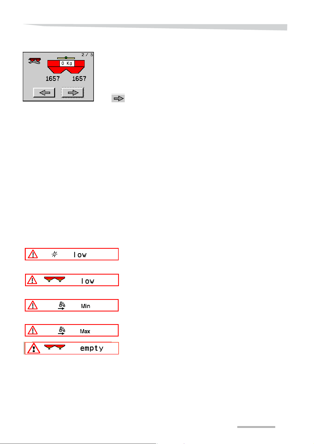
System settings
On the second screen, below the left hopper half, you will see the existing weighcell signal for the current hopper weight. Below the right
hopper half, you will see the signal value contained in the control system memory. The value is saved during the previous hopper calibration. On the screen, you can overwrite the signal value saved in the
memory with the new, current value below the left hopper half.
Press the right arrow to overwrite the value.
The new value is saved and the screen is closed.
The signal value in the control system memory is now replaced by the
signal value belonging to the current hopper weight. The control system will now use this value to calculate the hopper content.
Alarms
User's alarms
If the control system cannot perform the requested function, a warning
will appear on the screen. The system has 3 different types of alarm:
• User's alarms; this appear when the spreading function cannot be
performed adequately or at all.
• System alarms; parts of the system are not functioning well or at
all.
• Weigh cell alarms; the signal value conflicts with the calibrated val-
ues stored in the control system memory.
If a user's alarm appears on the control box screen, the spreader
cannot carry out the requested function adequately or at all. However ,
the machine is in good condition, nothing is broken. You can fix the
cause of the alarm yourself.
The spreading discs are not turning. The PTO shaft is not connected
or the coupling is not coupled. The alarm does not appear if you have
set an incorrect PTO shaft rpm.
The hopper content has gone below the set alarm level.
See also section »Hopper alarm« on page 76.
The driving speed is too low for accurate spreading. The dosing units
are almost closed. Use the fine application kit or increase the driving
speed.
The driving speed is too high for accurate spreading. The dosing unit s
are completely open. Decrease speed.
Hopper is 100% empty from spreading
If you have sprayed the hopper completely empty this alarm will
sound.
It is time to lubricate the machine. This alarm is displayed every 8
hours
See also »Alarm lubrication« on page 81
95
Page 96
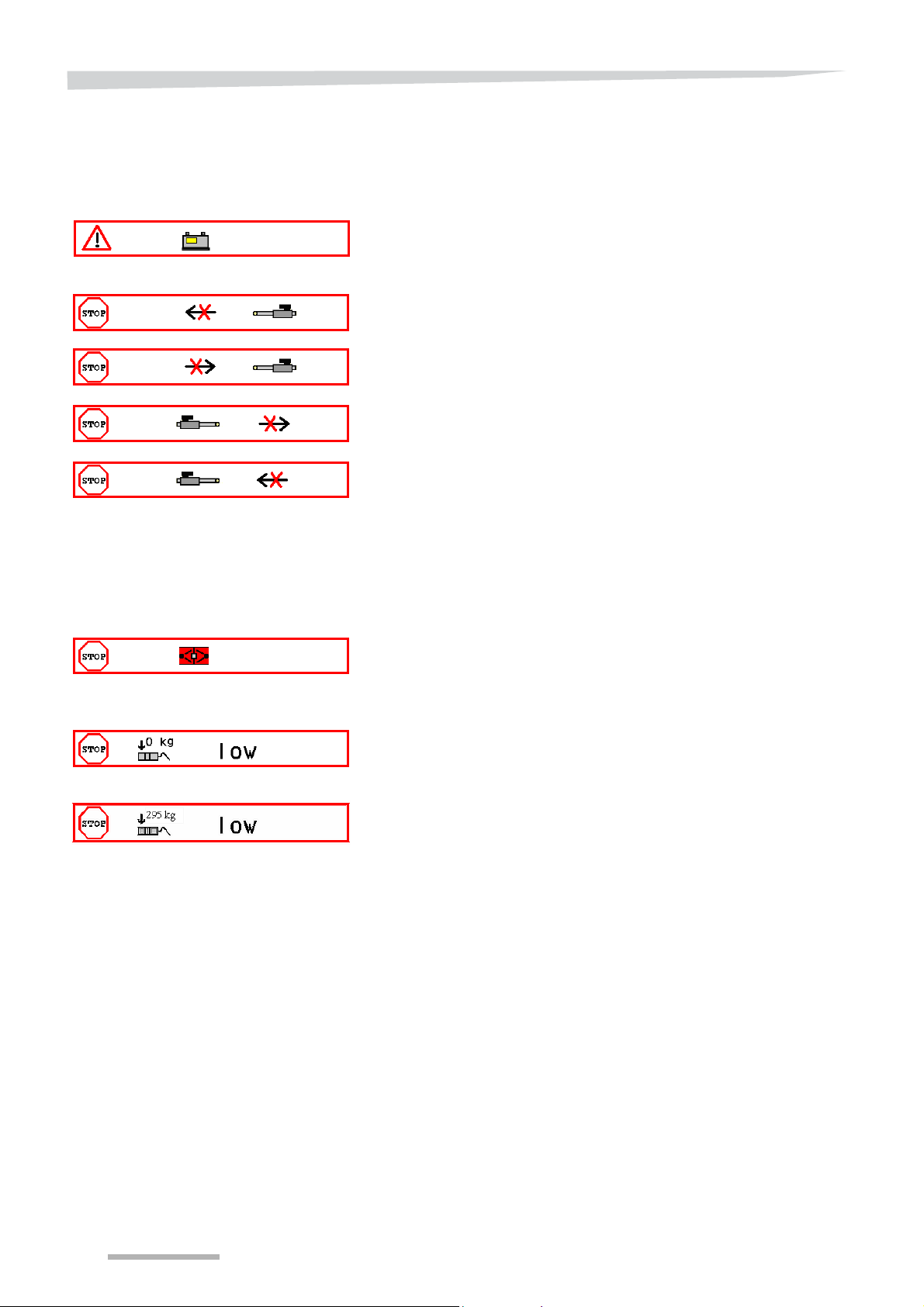
System settings
System alarms
Weighcell alarms
If a system alarm appears on the control box screen, you must stop
immediately. The spreader cannot perform the requested function
adequately because the power supply is insufficient or the actuators
are not responding correctly. Fix the failure before working any further.
The supply voltage of the control system has gone below the set alarm
level. Repair the power supply, recharge the battery or replace it.
See also section »Supply voltage alarm« on page 81.
The left actuator cannot open. Check the feeder cable to the actuator
and whether hard objects or dirt are blocking the dosing units.
The left actuator cannot close. Check the feeder cable to the actuator
and whether hard objects or dirt are blocking the dosing units.
The right actuator cannot open. Check the fe eder cable to the actuator
and whether hard objects or dirt are blocking the dosing units.
The right actuator cannot close. Check the feeder cable to the actuator
and whether hard objects or dirt are blocking the dosing units.
If a weighcell alarm appears on the control box screen, yo u must stop
immediately. The spreader cannot carry out the requested function
adequately because the signal value conflicts with the saved
calibrated weighcell or reference sensor signal value.
When the spreader is at an angle, the reference sensor signal value
is higher than when the spreader is level. The signal value must be
highest when the spreader is level. The spreade r reference sensor
must be recalibrated. Consult your dealer.
The weighcell signal value for an empty hopper is too low. Consult
your dealer.
The signal value for the displayed weight of a level machine does not
agree with the signal value when the machine is at an angle. Consult
your dealer.
96
Page 97
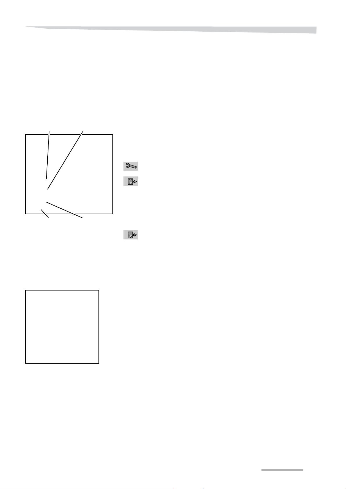
System settings
S
Reference sensor
signal value
S
Empty hopper
signal value
S
Signal value in
slanting position
S
Signal value for
given hopper filling
Service information
Weighing system
information
The control system can provide all kinds of information on the machine
as well as store it in some cases. This information will be used by the
dealer when checking the machine or by service engineers in case o f
problems and failures.
The bottom half of the 'Hopper&Act Calibration' screen contains
information on signal values of the weighcell and reference sensor.
The left column contains the current signal values, the right column
contains the signal values that are saved in the control system during
calibration of the relevant cell.
By means of the current and saved signal values, ca libration can be
controlled and failures can be detected.
The ’Hopper&Act Calibration’ screen can be reached from the main
screen as follows:
Press the key switch on the main screen; you will now go to the
'Curve Calibration' screen.
Press the scroll key to go from the 'Curve calibration' to the 'Pin'
screen.
Enter the pin code (= 5).
See section »Spreader calibration« on page 92
Press the OK key. The ’Settings’ screen will now appear.
Control box information
Press the scroll key to go to the ‘Hopper&Act Calibration’ screen.
The meaning of the symbols and values in the top half of the screen
is explained in
section »Spreader calibration« from page 92.
You can find some control box data can be found in the ‘Terminal
Configuration’ screen. The top half concerns date and time, among
other things, while the bottom half displays data on the screen. You do
not have to adjust these data.
97
Page 98
System settings
Diagnosis menu
Software version
System information and
totals
You will find the lens key in every settings and service menu screen.
By pressing this key, you will reach the diagnosis menu. In the
diagnosis menu, you will find information on the control system,
software, current measurement data, etc.
In this screen, you will see the software version and the date on which
it entered service.
By pressing the scroll key on the screen that display s the software
version, you will reach the screen with system information and
machine totals.
The control system constantly registers all incoming signals. The
control system uses some of them to d rive th e sp r ea der, while others
form limiting conditions for a well functioning control system, which are
therefore continuously compared with minimum values. The alarm is
sounded, for instance, based on these details.
The left and right actuator can be steered separately inwards or
outwards with the plus keys. This function is mostly reserved for
service engineers.
The machine also registers the following details:
• total working time (Time),
• total mass distributed (Mass),
• total area treated (Area),
• average application rate (Rate).
These totals are given in the lower part of the screen.
98
Page 99
System settings
Logbook
AEF ISOBUS Certification
The screen indicating important events is displayed by pressing the
logbook key on the screen in which the softwa re ver sion is disp layed .
The control system registers when and how often important events
took place. An alarm is also displayed in most instances. The history
can be very useful in solving failures.
A few less important events can be deleted by pressin g the ‘Clear’ key.
It is not recommended that this key be used, however.
The last screen in the ISOBUS communication menu shows the
statement that this software system complies with the AEF ISOBUS
database standards.
The AEF, Agricultural Industry Electronics Foundation, tests the
software system for communication with other systems. By means of
this it can be checked beforehand whether the systems on sale can
work together.
99
Page 100

Activities before spreading
Activities before spreading
Find the correct
settings for
setting the
spreader
Characteristics of the
fertiliser
Avoid contact with the fertiliser and other materials
You are likely to come in contact with the fertiliser or other materials
that you want to spread while filling, adjusting and testing the
spreader. W ear protective clothing and gloves, read the safety in structions provided by the supplier and follow their directions. Contact with
these materials could cause physical injury.
You will find the details for properly adjusting your spreader in the
spreading charts in the spreading charts book and on the website.
See also section »Online spreading chart service« on page 104.
The spreading charts indicate what type of fertiliser is best suited to
achieving good distribution. Correct adjustment depends on the
characteristics of the fertiliser, not the brand! Determine the characteristics of the fertiliser, therefore, and find the spreading chart with
similar features. Use the chart, even if the brand of the fertiliser differs
from the nearest comparable fertiliser!
Select the spreading chart based on the characteristics of the
fertiliser, not on the basis of the brand!
The following physical characteristics of the fertiliser have to be
collected before consulting the spreading chart book or the website
• type and pattern of the granules
see the section »Determine the type and pattern of the
granules« below,
• distribution (= composition of granules of various sizes),
see section »Determining distribution« on page 102,
• similar weight,
See section »Determining similar weight« on page 103.
Determine the type and
pattern of the granules
I
NDICATION
Distribution is the most vital characteristic of the fertiliser when it
comes to spreading. You can make the first selection from the
spreading charts based on the distribution. Never use a spreading
chart for another type of fertiliser, even if the distribution is very similar!
You can determine which spreading chart compares the best to the
fertiliser you are using based on similar weight.
Select the type of fertiliser from the spreading chart that is closest to
the type of fertiliser that you are using.
The characteristics of the various types of fertiliser are so different that
using a spreading chart for another type of fertiliser, even if the
distribution is the same, could provide a bad spreading pattern and
harm the crop!
100
 Loading...