

Page 1
1
Installation
6
Access
to the
mobile
viewer
5
Network
Setting
Basic Layout
Rear View
J
Since the cable quality may affe ct directly to the video quality depending on the dista nce between the camera and DVR, it is recommended to consult an au thorized installer when installing the DVR.
Network Connection
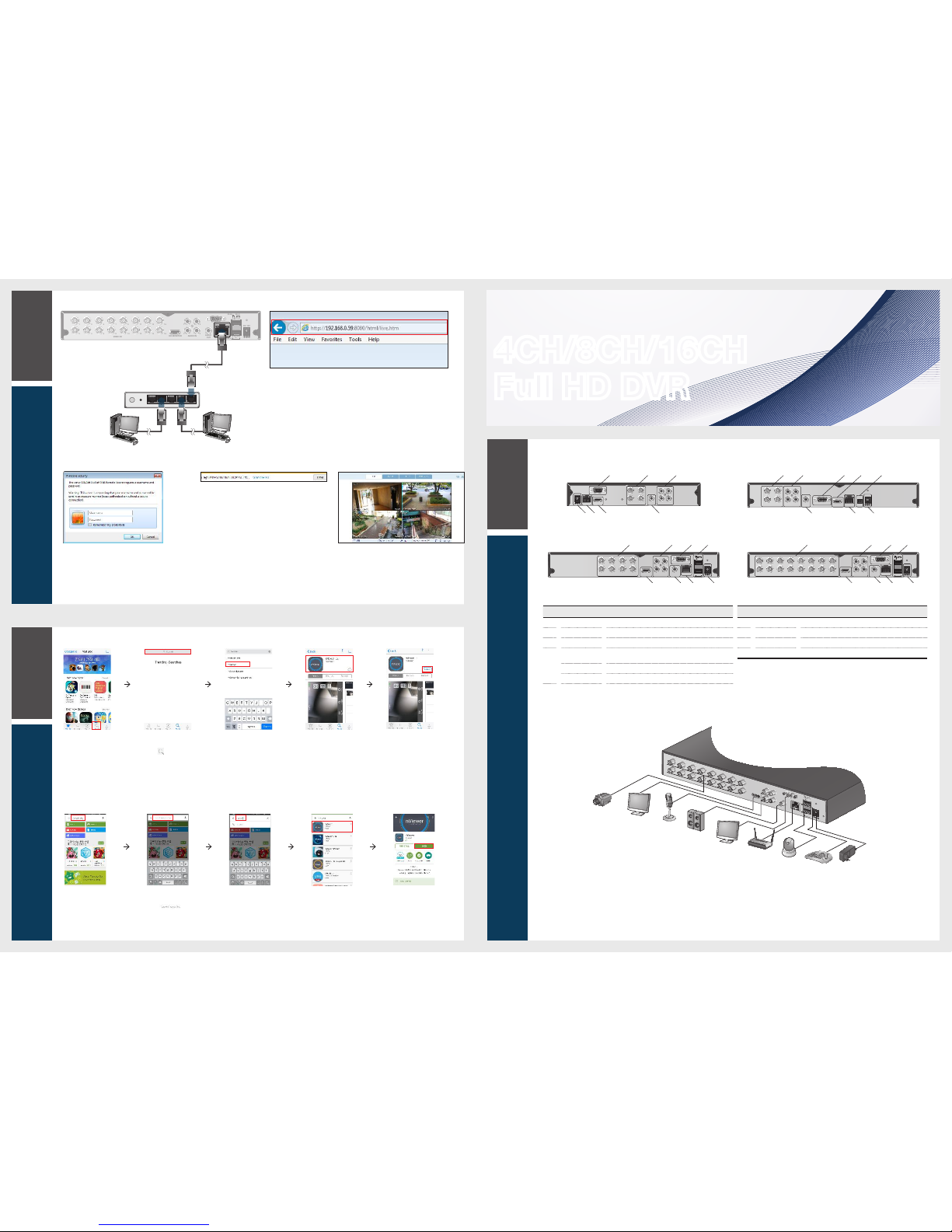
To access the Web Viewer
2.
When the login dialog appear s, enter the user name
and password.
The default ID and password
- User name : ADMIN
- Password : 1234
Be aware when you enter the ID whether it is upper or lower case
3.
Click the upper warning bar to install the ActiveX
before enabling the add-in functi on.
4.
When the security warnin g window appears, click
<Install>.
5.
When the ActiveX is installed completel y, you will
see the live screen.
For more information about using the Web viewer, refer to
the user manual.
1.
Open the browser and enter the IP address of DVR, or enter the URL address in
the address bar.
ex) if you use the DDNS of the DVR:
http://00115f123456.dvrlink.net :8080
If you do use the IP address of the DVR:
http://192.168.0.210 : 8080
For more information about the router and netwo rk settings, refer to the user
manual of the respective product.
4CH/8CH/16CH
Full HD DVR
Quick Guide
How to download and access the Android-specific viewer
1.
From your
smart phone,
access the
Market.
2.
From the top
menu bar, click
<
>.
3.
Type "nViewer"
in the search
bar.
4.
Select "nViewer"
to install it.
5.
When done,
select "nViewer"
again and
install it.
How to download and access the iOS-specific viewer
1.
From your iPhone,
access App store.
2.
From the lower
menu bar, click
<
>.
3.
Type "nViewer" in
the search bar.
4.
Select "nViewer"
to install it.
5.
When done,
select "nViewer"
again to run it.
4 channels (1HDD)
8 channels (2HDD)
4 channels (2HDD)
16 channels (2HDD)
No. Name Description
a
VIDEO IN Video input terminal for came ras.
b
AUDIO IN Port for audio input.
c
VGA VGA monitor video output port.
d
RS485
Ports for communication with ex ternal devices such as PTZ
camera and system keyboard.
RELAY Relay Terminal output port.
ALARM IN Alarm input signal port.
No. Name Description
e
HD MONITOR HD monitor video output port.
f
AUDIO OUT Port for speaker connection.
g
ETHERNET Network port for connectio n to the Internet, router or hub.
h
DC 12V Power input port. Connect to a 12V adaptor.
DC 12V
VGA
113
2
234
4
HD MONITOR
VIDEO IN
AUDIO
OUT
AUDIO IN
ENTHERNET
h g e
a bc
f
1 3
1 3
2 4
2 4
VIDEO IN
AUDIO IN
AUDIO
OUT
VGA
HD MONITOR
ETHERNET
DC 12V
RS485
D+
D-
c e dba
f g h
123456789101112131415
16
VIDEO IN
RS485 RELAY
D+
NC
NO
COM
AUDIO
OUT
VGA
HD MONITOR
ETHERNET
DC 12V
1 3
2 4
AUDIO IN
ALARM IN
IN1
IN2
IN3
IN4
GND
ba
e f g
h
c d
1 3 5 7
2 4 6 8
VIDEO IN
RS485 RELAY
D+
NC
NO
COM
AUDIO
OUT
VGA
HD MONITOR
ETHERNET
DC 12V
1 3
2 4
AUDIO IN
ALARM IN
IN1
IN2
IN3
IN4
GND
ba
e f g
h
c d
1
2
3
4
5
6
7
8
9
10
11
12
13
14
15
16
VIDEO IN
RS485 RELAY
D+
NC
NO
COM
AUDIO
OUT
HD MONITOR
ETHERNET
DC 12V
1 3
2 4
AUDIO IN
ALARM IN
IN1
IN2
IN3
IN4
GND
DC 12V
Power
Camera
Sensor
IP Router
or HUB
Control
Devices
VGA
MONITOR
HD
MONITOR
Speaker
MIC
123456789101112131415
16
VIDEO IN
RS485 RELAY
D+
NC
NO
COM
AUDIO
OUT
VGA
HD MONITOR
ETHERNET
DC 12V
1 3
2 4
AUDIO IN
ALARM IN
IN1
IN2
IN3
IN4
GND
4WANRESETPWR 3 2 1
Local PC
Local PC
Broadband router
or hub
Page 2

3
Recording
5
Network
Setting
4
Search
Item Descrip tion
Select one of the system setup, search and backup menu items befo re
accessing it.
Show the ID of the user who has currently logged in.
Edit the screen layout to show the status bar and timeline at all times or onl y
when the mouse cursor hovers on the status bar/timeli ne.
Used to select a split mode.
Select Auto Sequence Mode.
When a user arranges channe ls on desired tiles of split screen, such setting
is listed for later access. Selecting a scree n setup directly switches the screen
mode as configured.
Display or hide the OSD menus on the screen.
Move to the PTZ screen. You can control the PTZ operations of a PTZcompliant camera on the PTZ scre en.
Item Descrip tion
Move to the Zoom screen.
Display the log list of the recent recording events.
You can use the camera supporting the audio input to listen to the audio.
Start the emergency reco rding.
Blinks when the event occurs. It will not blink if no action to the event has bee n
set.
Click to view information about the event that occur red.
Check if network connectio n is made via an external PC or mobile device.
Click this to view the details of the concurrent user s and to check the network
connection status.
Show the disk space information. If you have set the disk overwr ite mode, it will
be displayed "OW" (Over Write) from the start point of the overwri ting.
5
Display the current time and date.
Language Setting
Date/Time Setting
Status Bar
You can use the buttons on the bottom status bar to control the DVR.
1.
Select <MENU> - <SYSTEM SETUP> from the status bar.
2.
From <SYSTEM SETUP> - <DISPLAY>, select <OSD>.
3.
Select a preferred language.
4.
Click <APPLY>.
1.
Select <MENU> - <SYSTEM SETUP> from the status bar.
2.
From <SYSTEM SETUP> - <SYSTEM>, select <DATE/TIME>.
3.
Specify the display format of the curre nt time and date.
J
As the existing data in the same time and date will be deleted if duplic ates are found, back up the
existing data for later use.
4.
Click <APPLY>.
Item Description
Channel No Di splay the number of the current channel.
Play Start playing the video of the selec ted channel from the specified time.
Zoom Move to the Digital Zoom.
Snapshot Capture
Capture the current live video and save it in the .jpeg format.
Then, you can save the captured video in the HDD or export it to
an external USB memory devic e.
Item Description
Timeline Date
5
Display the date of the current timeline.
Click this to select a desired date of the timeline.
Zoom in/out the
timeline
Expand or collapse the timeli ne.
Navigation
through Timeline
Move to the previous or next point of time in the timeline.
You can also use the mouse wheel to navigate through the
timeline.
Timeline Bar
Represent the recorded data. The co lor of each bar
indicates:
~
Green : Continuous Recording
~
Red : Alarm Recording
~
Blue : Motion Recording
~
Yellow: Panic Recording
Double-click the timeli ne to move to the Playback mode. Drag and drop it to make backup or
event search for the specified area.
Video Window Qu ick Menu
Status Bar
Time
line
2
Getting
Started
Automatic Recording Setting
1.
You can select <MENU> - <RECORD SETUP>
from the status bar.
2.
Set <RECORD SETUP MODE> to <AUTO
CONFIGURATION>.
3.
Select "Automatic Record Configuration Mod e".
ALWAYS HIGH VIDEO QUALITY : Recording will
proceed in the best quality rega rdless of the event
at all times.
As this option will always make recording in the
best quality, the recording period is the sho rtest
compar
ed to the other record modes.
MOTION RECORD : Recording will proceed onl y
if a motion is detected.
Time Search
1.
From the <SEARCH> menu, select <TIME
SEARCH>.
2.
Specify the search date and time from the cal endar
in the left corner of the screen.
3.
You can identify the type of the recording data by the
color in the bar.
Yellow Green (PRE RECORDING) : The pre-
recording is performe d on the recording data
after you set the <PRE RECORDING TIME> from
<OPERATION MODE>.
Green (Continuous) : The continuous rec ording is
performed on the recordin g data.
Red (Alarm) : The alarm event recording is
performed on the recordin g data.
Blue (Motion) : The motion event recording is
performed on the recordin g data.
Yellow (Panic) : The panic manual recording is
performed on the recordin g data.
4.
Click to move to a desired start time in the time bar,
or use the buttons at the bottom of the status bar to
make search.
5.
Select an item to play and click <PLAY>.
J
Click to move to a desired time, or simply double-click a
desired time in the time bar to play the video data on that
time.
For details on thumbnail search and event se arch, refer to
the user manual.
Network Connection Setting
To configure the network settings
1.
Connect the [ETHERNET ] port in the rear panel to
the router.
2.
Connect the [ETHERNET ] port of the router directly
to the fixed IP LAN cable, or connect it to the ADSL
modem.
3.
Check the network address infor mation if using a
network environment conn ected to the same router.
4.
Enter the network setting menu of the DVR and
provide the IP address.
5.
When the network configuratio n is complete,
proceed with the
DDNS settings to allow access to
the DVR from outside.
From the main menu of the DVR, move to <SYSTEM
SETUP> - <NETWORK> - <DDNS>.
6.
Rename the DVR. (The default name of the DVR is the
MAC address of the DVR.)
Enter a desired name in combination of charac ters and
numbers.
1)
From the main menu of the DVR, move to <SYSTEM
SETUP> - <NETWORK> - <IP SETUP>.
2)
Uncheck the DHCP checkbox and provide the
n
ecessary informat ion manually.
(Check the network address informa tion in the
network environment set tings and enter the correct
information.)
IP ADDRESS : 192.168.0.123 (enter the network IP
address.)
GATEWAY : 192.168.0.1 (enter the gateway address.)
SUBNET MASK : 255.255.255.0 (type the subnet
mask.)
1ST, 2ND DNS SERVER : 168.126.63.1 (enter the
address of a DNS server.)
7.
When done, click <DDNS REGISTRATION TEST>
and <DDNS CONNECTION TEST> in this order.
If you receive a success message. Chec k the DVR
address and click <APPLY> at the bottom.
8.
Check the DVR address and the Web service por t in
the network settings to make sure that any Internetconnected PC can access the DVR.
9.
If you type "mydvr" for the DVR name from the DDN
item, the address of the Web viewer is "h
ttp://mydvr.
dvrlink.net: 8080".
ALARM RECORD : Recording will proc eed only if
an alarm event occurs.
MOTION/ALARM RECORD : Recording will
proceed only if a motion is detected or an alarm
event occurs.
INTENSIVE MOTION RECORD : Normally
recording will be perform ed in a low quality.
However, the quality will switch to high if a motion
is detected.
INTENSIVE ALARM RECORD : Norma lly
recording will
be performed in a low quality.
However, the quality will switch to high if an alarm
event occurs.
INTENSIVE MOTION/ALARM RECORD : Normal ly
recording will be perform ed in a low quality.
However, the quality will switch to high if an alarm
event occurs or a motion is detected.
4.
Click <APPLY>.
Enter an IP address that falls in the private IP range
provided by the router.
ex) 192.168.1.2~254, 192.16
8.0.2~254, 192.168.
3)
When done, configure the port for warding for RTSP
and Web Service ports by clicki ng Port Forwarding.
(The default value of the Web servic e port is 8080.)
4)
Click <PORT FORWARDING> for each. You will see
the confirmation message. Clic k <APPLY> and exit
the menu.
5)
The network settings of the DVR are complete.
Some router models may not support UPNP prope rly.
If you see a failur
e message after <PORT FORWARDING>
settings, refer to the user manual of the router and configur e
the DMZ or port forwarding setti ngs manually.
Timeline
Quick Menu
Log In
Live Screen
1.
When the system starts, the login screen ap pears.
2.
Select the user ID and enter the password.
The default user ID is
“
ADMIN”; the default password is “1234”.
3.
Click <OK>.
J
For safe and secure use of the product, change the password af ter purchasing.
 Loading...