

Page 1
Vicon Industries Inc. does not warrant that the functions contained in this equipment
will meet your requirements or that the operation will be entirel y error free or perform
precisely as described in the documentation. This system has not been designed to be
used in life-critical situations and must not be used for this purpose.
Document Number: 8009-8298-20-00 Product specifications subject to change without
notice. Iss ued: 7/17 Copyright © 2017 Vicon Industries Inc. All rights reserved.
Vicon Industries Inc.
Tel: 631-952-2288) Fax: 631-951-2288
Toll Free: 800-645-9116
24-Hour Technical Support: 800-34-VICON
(800-348-4266) UK: 44/(0) 148 9
-566300
www.vicon-security.com
XX298-20-00
ENC-H264-16 Video Encoder
Quick Guide
Page 2
WARNING
TO REDUCE THE RISK OF FIRE OR ELECTRIC SHOCK, DO NOT EXPOSE THIS PRODUCT TO RAIN OR MOISTURE. DO NOT INSERT ANY
METALLIC OBJECT THROUGH THE VENTILATION GRILLS OR OTHER
OPENINGS ON THE EQUIPMENT.
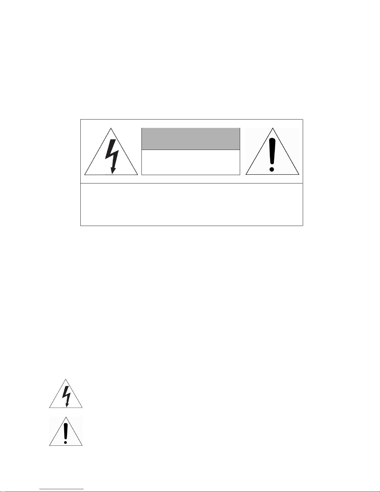
CAUTION
EXPLANATION OF GRAPHICAL SYMBOLS
The lightning flash with arrowhead symbol, within an equilateral triangle, is in- tended to alert
the user to the presence of dangerous voltage within the products
enclosure that may be of
sufficient magnitude to constitute a risk of electric shock
to persons.
The exclamation point within an equilateral triangle is intended to alert the user to the
presence of important operating and maintenance (servicing) instructions
in the literature
accompanying the product.
CAUTION
RISK OF ELECTRIC SHOCK
DO NOT OPEN
WARNING: TO REDUCE THE RISK OF ELECTRIC SHOCK,
DO NOT REMOVE COVER (OR BACK).
NO USER-SERVICEABLE PARTS INSIDE.
REFER SERVICING TO QUALIFIED SERVICE PERSONNEL
Page 3

FCC COMPLIANCE STATEMENT
CE COMPLIANCE STATEMENT
This device complies with Part 15 of the FCC Rules. Operation is subject
to the following two conditions: (1) this device may not cause harmful interference, and (2) this device must accept any interference received, including
interference that may cause undesired operation.
FCC INFORMATION: This equipment has been tested and found to
comply with the limits for a Class A digital device, pursuant to Part 15 of
the FCC Rules. These limits are designed to provide reasonable protection
against harmful interference when the equipment is operated in a commercial environment. This equipment generates, uses, and can radiate radio
frequency energy and, if not installed and used in accordance with the instruction manual, may cause harmful interference to radio communications.
Operation of this equipment in a residential area is likely to cause harmful interference in which case the user will be required to correct the interference
at his own expense.
CAUTION: Changes or modifications not expressly approved by the party
responsible for compliance could void the user’s authority to operate the
equipment.
This Class A digital apparatus complies with Canadian ICES-003.
Cet appareil nume
`
rique de la classe A est conforme a
´
la norme NMB-003 du
Canada.
WARNING
This is a Class A product. In a domestic environment this product may cause
radio interference in which case the user may be required to take adequate
measures.
CAUTION
RISK OF EXPLOSION IF BATTERY IS REPLACED BY AN INCORRECT TYPE.
DISPOSE OF USED BATTERIES ACCORDING TO THE INSTRUCTIONS.
Page 4

IMPORTANT SAFETY INSTRUCTIONS
1.
Read these instructions.
2.
Keep these instructions.
3.
Heed all warnings.
4.
Follow all instructions.
5.
Do not use this apparatus near water.
6.
Clean only with dry cloth.
7.
Do not block any ventilation openings. Install in accordance with the manufacturer’s instructions.
8.
Do not install near any heat sources such as radiators, heat registers, stoves, or other apparatus
(including amplifiers) that produce heat.
9.
Do not defeat the safety purpose of the polarized or grounding-type plug. A polarized plug has two
blades with one wider than the other. A grounding type plug has two blades
and a third grounding prong.
The wide blade or the third prong are provided for your safety,
If the provided plug does not fit into your
outlet, consult an electrician for replacement of the
obsolete outlet.
10.
Protect the power cord from being walked on or pinched particularly at plugs, convenience
receptacles, and the point where they exit from the apparatus.
11.
Only use attachments/accessories specified by the manufacturer.
12.
Use only with the cart, stand, tripod, bracket or table specified by the
manufacturer, or sold with the apparatus. When a cart is used.
Use caution
when moving the cart/apparatus combination to avoid injury from tip-over.
13.
Unplug this apparatus during lightning storms or when unused for long
periods of time.
14.
Refer all servicing to q ualif ied ser vice per sonnel. Ser vic ing is required when the apparatus has
been damaged in any way, such as
power-supply cord or plug is damaged,
liquid has been spilled or objects have fallen into the apparatus, the apparatus has been exposed to
rain or moisture,
does not operate normally, or has been dropped.
15.
CAUTION
−
THESE SERVICING INSTRUCTIONS ARE FOR USE BY
QUALIFIED SERVICE PERSONNEL ONLY. TO REDUCE THE RISK OF ELECTRIC
SHOCK DO NOT PERFORM ANY SERVICING OTHER THAN THAT CONTAINED IN
THE OPERATING INSTRUCTIONS UNLESS YOU ARE QUALIFIED TO DO SO.
16.
Use satisfy clause 2.5 of IEC60950-1/UL60950-1 or Certified/Listed Class 2
power source only.
17.
ITE is to be connected only to PoE networks without routing to the outside plant.
Page 5
1. Overview
1.1 Package Contents
The device package contents consist of the following:
Note
Please check that all components are included.
Table 2-1 Package content s
No Name No Name
1 Encoder 6 SATA cable
2 DC Power Adapter & Power cord 7 SATA power cable
3 Mouse 8
HDD fixing screw (not relevant when used
as encoder)
4 Quick guide
1.2 Part Description
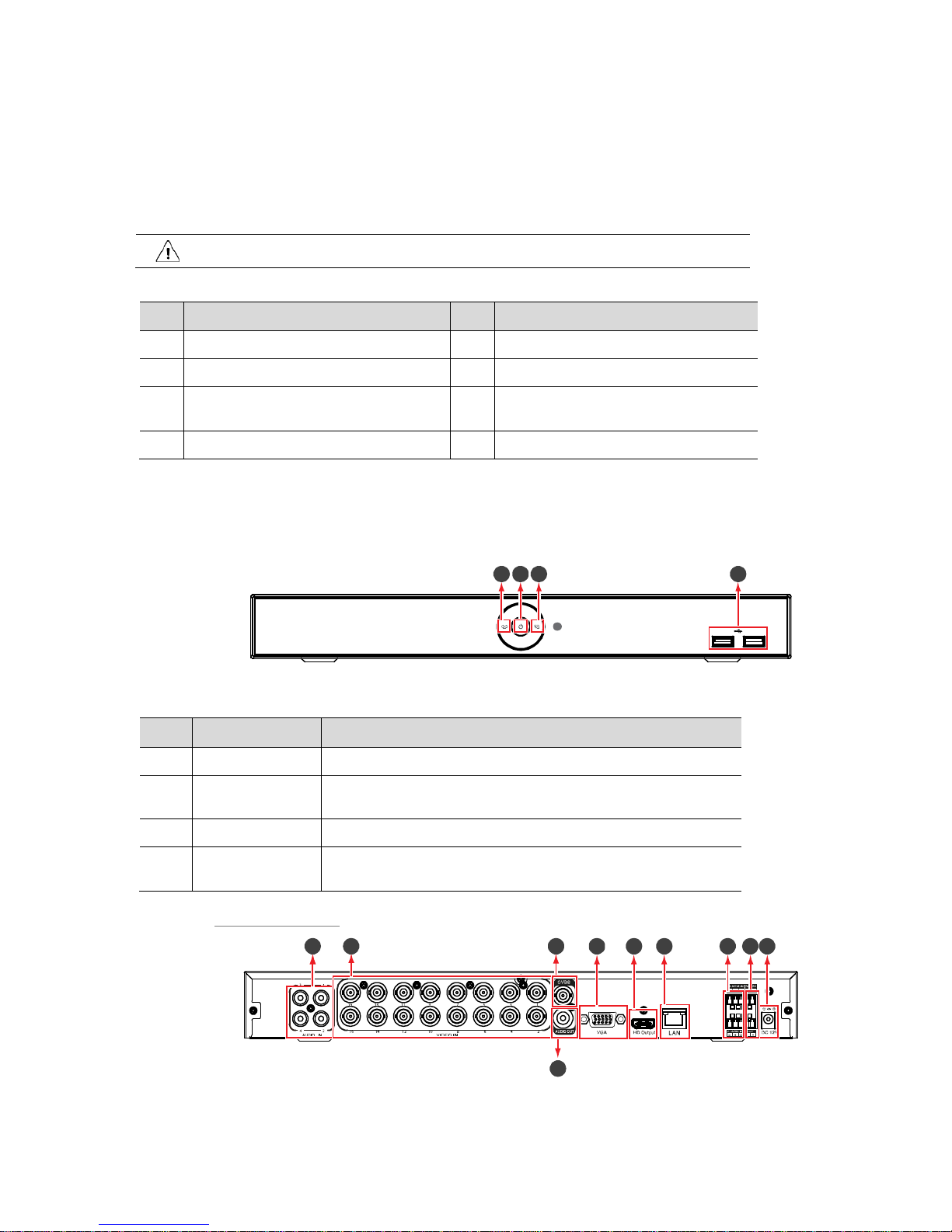
Each part is listed in the below:
Figure 2-1 Name and Connection of each front section
Table 2-2 Name and Function of each front section
No. Name Function
1 Power status LED Indicates device is ON/OFF
2
Recording status
LED
Indicates recording in process. Not relevant when used as encoder
3 Network LED With a network viewer, indicates network in connection
4 USB port
USB port is for connection to USB mouse or for firmware upgrade and
data back-up
16ch DVR/Encoder
Figure 2-2 Name and Connection of each rear section of 16ch encoder
1
3
4
2
2
3
4
5
6
7
8
9
10
1
Page 6

Table 2-3 Name and Function of each rear section of 16ch encoder
No. Name Function
1 Audio In Camera audio input port
2 Video In Camera video input port
3 CVBS CVBS output port (depending on device types)
4 VGA VGA output port
5 HD Output HD output port
6 Network
Network connector
7 Alarm In/Out Alarm connector
8 RS485 RS-485 communication connector
9 12 VDC Connector with power supply
10 Audio Out Audio output port
Page 7
2. Installation
This chapter describes how to install the encoder.
Note: This device is meant to be used as an encoder streaming to a VMS; Vicon does not cover the
ability to use an HDD.
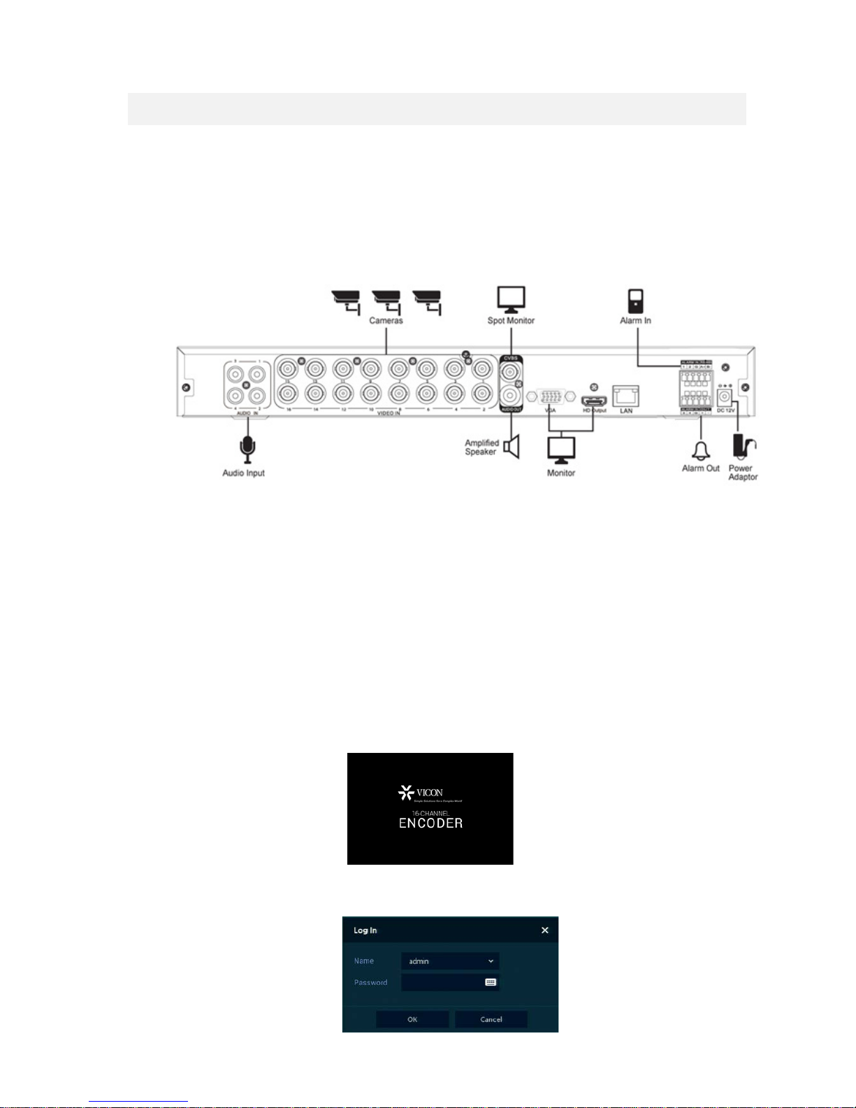
When installing a device, refer to the connection diagram below to make rear panel connections.
2.1 Starting the System
This is used for configuration purposes or if used as a spot monitor . Supplying power starts the system
operation as follows:
Connecting the Encoder to the Valerus VMS:
Initial configuration of the encoder requires setting up the IP address and PTZ channels if needed prior
to connecting it to the Valerus VMS. Connect a monitor and mouse to the unit to make the initial
configuration as needed. By default, the unit is setup for DHCP; if DHCP exists on the network, there is
no need to configure an IP. A static IP address can be configured as necessary. Once the IP address has
been established, the unit can be discovered and added to the Valerus VMS. This is done through the
Cameras and Encoders Configuration screen in Valerus.
Note: Make sure you have a Valerus third party license before connection to the Valerus VMS.
Upon start up, the following screen displays.
Then the login screen displays. The default user name is ADMIN and the default password is 1234. Vicon
recommends changing this password for increased security.
Page 8
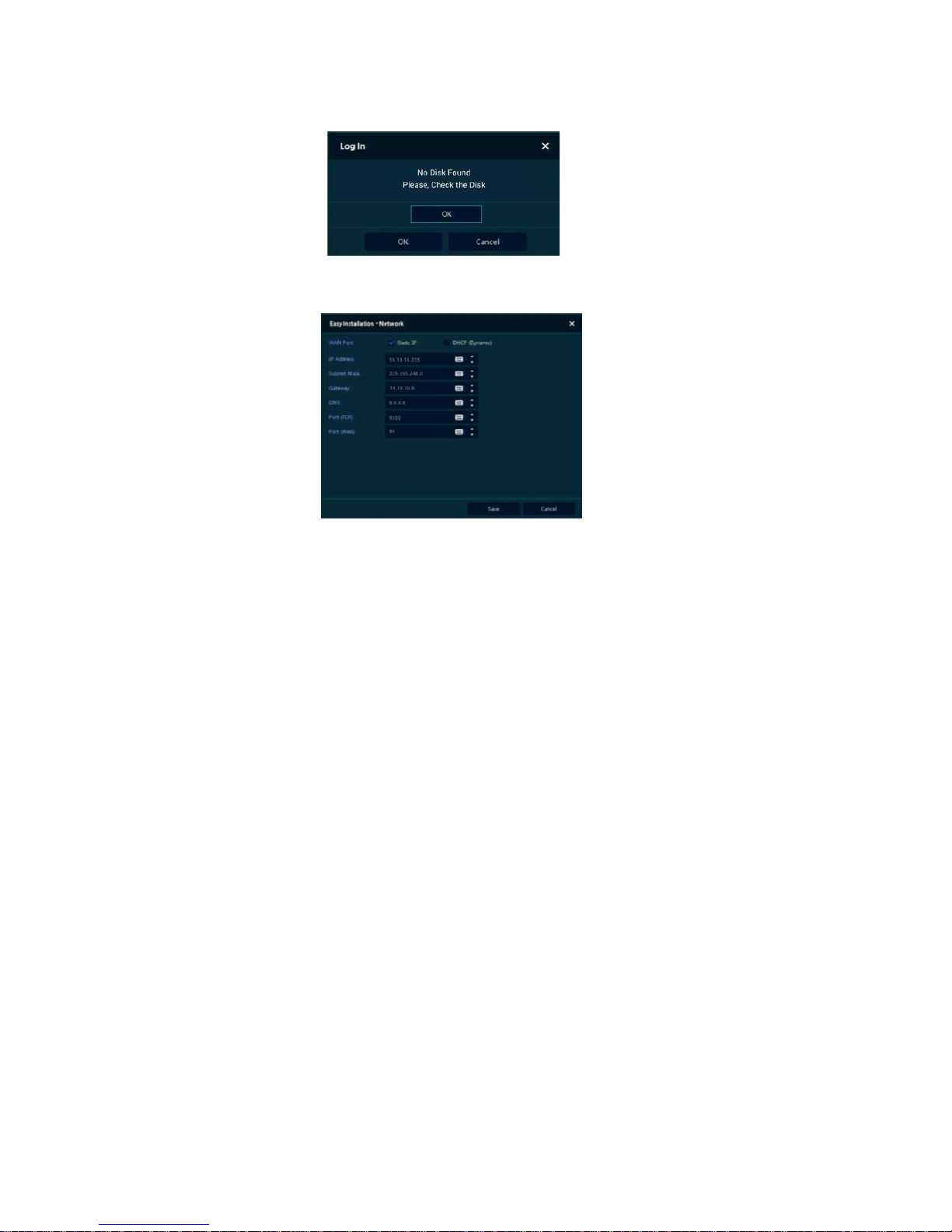
A message warning for No Disk Found may display. Click OK (as this is being used as an encoder).
Go to the Network configuration screen. Complete the fields to enter the IP address and all necessary
parameters and click Save.
The unit is now ready to be added to Valerus.
Note that if PTZ cameras are being used, these camera settings must be done prior to connecting the
encoder to Valerus. Go to t h e S et u p sc r een as shown in section 4.
Page 9
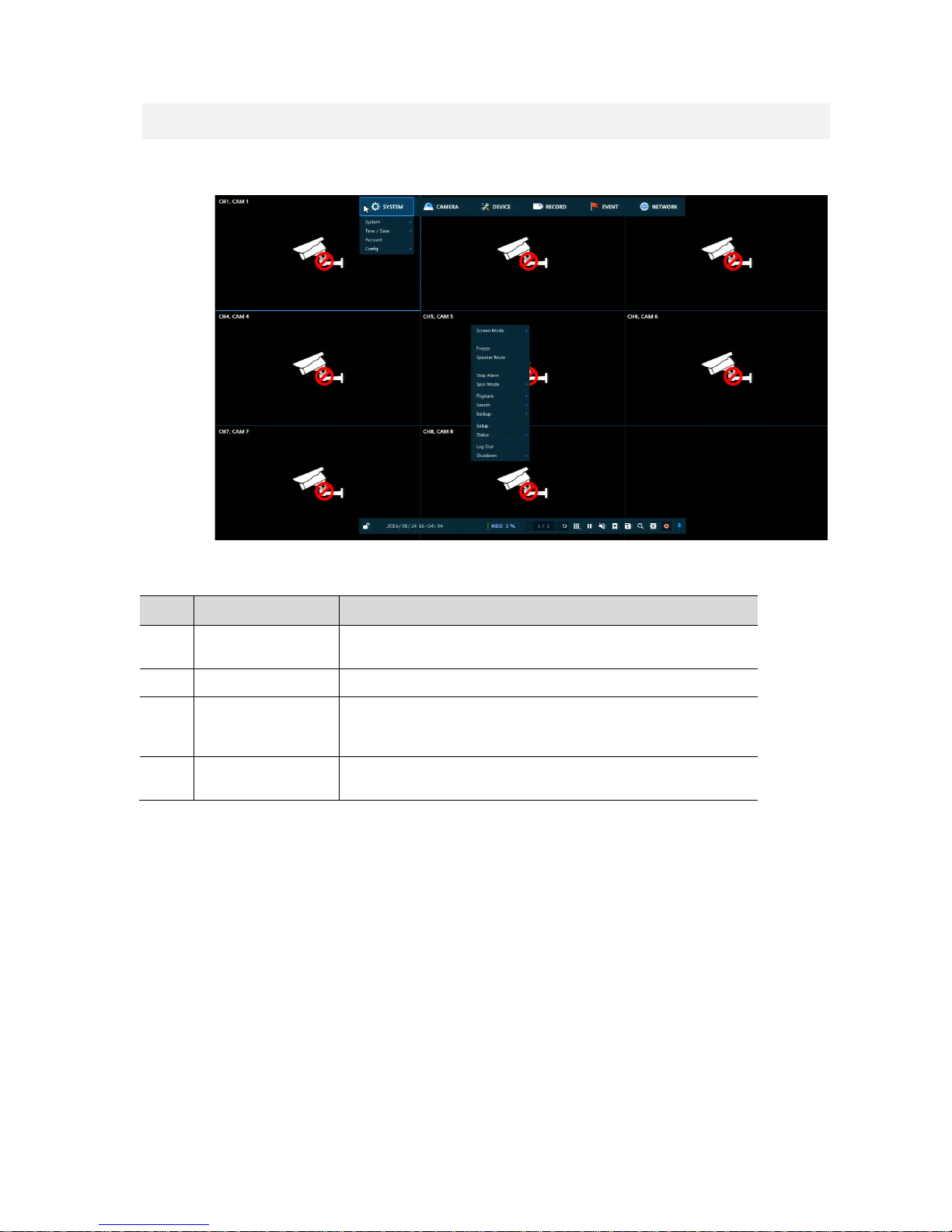
3. Live Screen Configuration
UI screen is configured as the figure below.
Figure 3-1 UI Screen Configuration
Table 3-1 Items and Description of UI Screen Configuration
No. Item Description
1
Setting menu
Setting menu is located in the corner of upper screen. See “Setup ” to
display detailed information about the setting menu.
2 Live screen Show live video of connected cameras.
3 Launcher menu
Launcher menu is located in the corner of bottom of the screen. See
“3.2 Live Launcher ” to display detailed information about the
launcher menu.
4 Quick menu
Clicking the right button of a mouse displays Quick menu. See “3.3
Quick ” to display detailed information about the quick menu.
Page 10
3.1 Icons in Live Screen
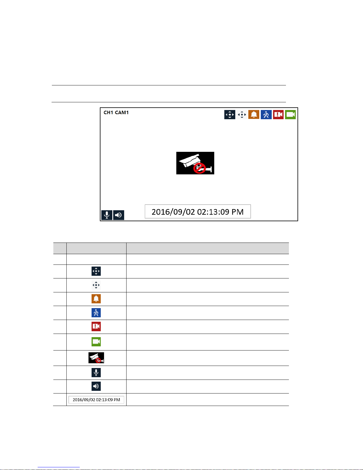
Each icon in the Live screen displays the present setting status or a function. UI screen consists of icons
as shown below. This device is meant to be used primarily as an encoder. In the case when local display
is used, this following information is provided.
Note
Chosen Live screen is marked by a blue frame; mouse-located Live screen is marked
by a yellow frame.
Figure 3-2 Live screen icon
Table 3-2 Live screen icon and its description
No. Icon Description
1 CH1 CAM1 Channel numbers and camera titles
2 A camera with PTZ function
PTZ control function in process
Recording in alarm event mode. Not relevant when used as encoder.
Recording in motion event mode. Not relevant when used as encoder.
Recording in panic recording mode. Not relevant when used as encoder.
Recording in consecutive recording mode. Not relevant when used as
encoder.
3 No camera input
4 Mic ON/OFF
Speaker ON/OFF
6
Displays present weat h er an d time
Page 11
3.2 Live Launcher Menu
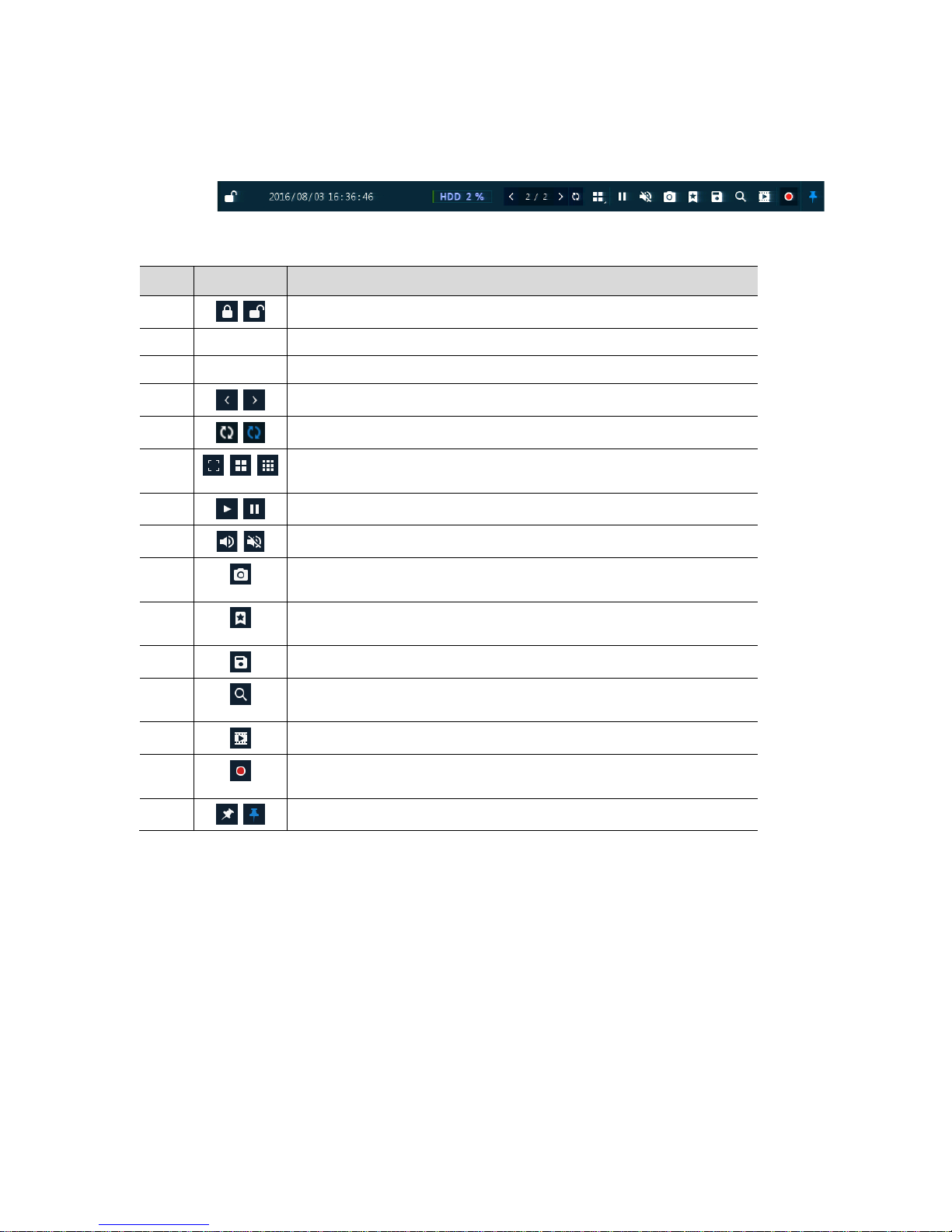
This chapter describes the Launcher menu at the bottom of the screen.
Figure 3-3 Launcher menu
Table 3-3 Launcher menu Item and Description
No. Item Description
1
Log in/out status and logged in ID
2 Date & Time Displaying present date and time
3 HDD Displaying HDD capacity in use. Not relevant when used as encoder.
4
Moving to previous/next partition screen.
5
Displaying live screen in order set (toggle)
6
Selecting partition mode to display in Live screen
(single screen, 4-, 9-, and 16- partition)
7
Stopping or replaying selected Live screen images (toggle)
8
Audio on or mute chosen in Live screen (toggle)
9
Capturing channel image of user’s selection. Not relevant when used as
encoder.
10
Bookmarking with date and time user’s selection. Not relevant when used as
encoder.
11
Make a backup video of user’s selection.
12
Searching recording data (time, event, and thumbnail). Not relevant when
used as encoder.
13
Play recorded data. Not relevant when used as encoder.
14
Starting immediate recording of selected channel. Not relevant when used as
encoder.
15
Locking or releasing Launcher menu (toggle)
Page 12
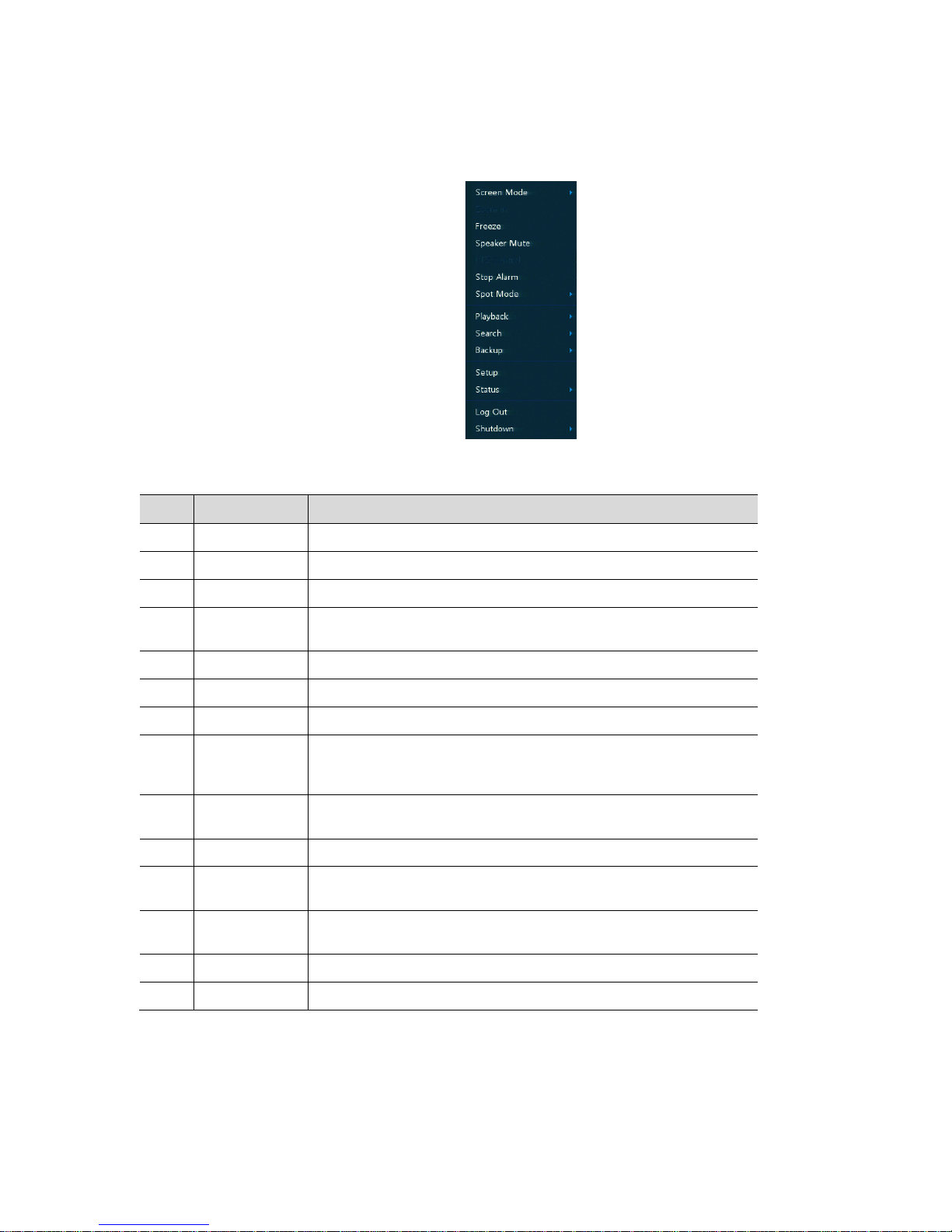
3.3 Quick Menu
This chapter e xplains the Quick menu when users click the right button of the mouse in Live screen.
Figure 3-4 Quick menu
Table 3-4 Quick menu Item and Description
No. Item Description
1 Screen Mode Selecting the partition mode of Live screen (Full, 2X2, 3X3 and 4x4).
2 Zoom in M agn i fy se lected Live screen (Zoom out, 2 times, 4 times and 8 times).
3 Freeze Stop or replay selected Live screen images (toggle)
4
Speaker
Output/Mute
Turn on/off a audio speaker
5 PTZ Control Controlling PTZ function
6 Stop Alarm Stop monitoring alarm output and event
7 Spot Mode Set the output mode of a spot monitor (Auto, Full, and 4x4)
8 Playback
Play selected Live screen images (before 30 sec, 1 min, 5 min, 10 min, 30
min, 1-hour, Go to last play time and Go to last record time). Not relevant
when used as encoder.
9 Search
Search recording data (time, event, thumbnail, and text). Not relevant
when used as encoder.
10 Backup Backup video user selected.
11 Setup
Open setting menu pop-up. For more information about setting menu, see
section “Setup.”
12 Status
Open a pop-up that displays device system log, event and recording status
(system log, event, and save)
13 Log in/Log out Log in/Log out
14 Shutdown Unplug or restart the device (shutdown, restart)
Page 13
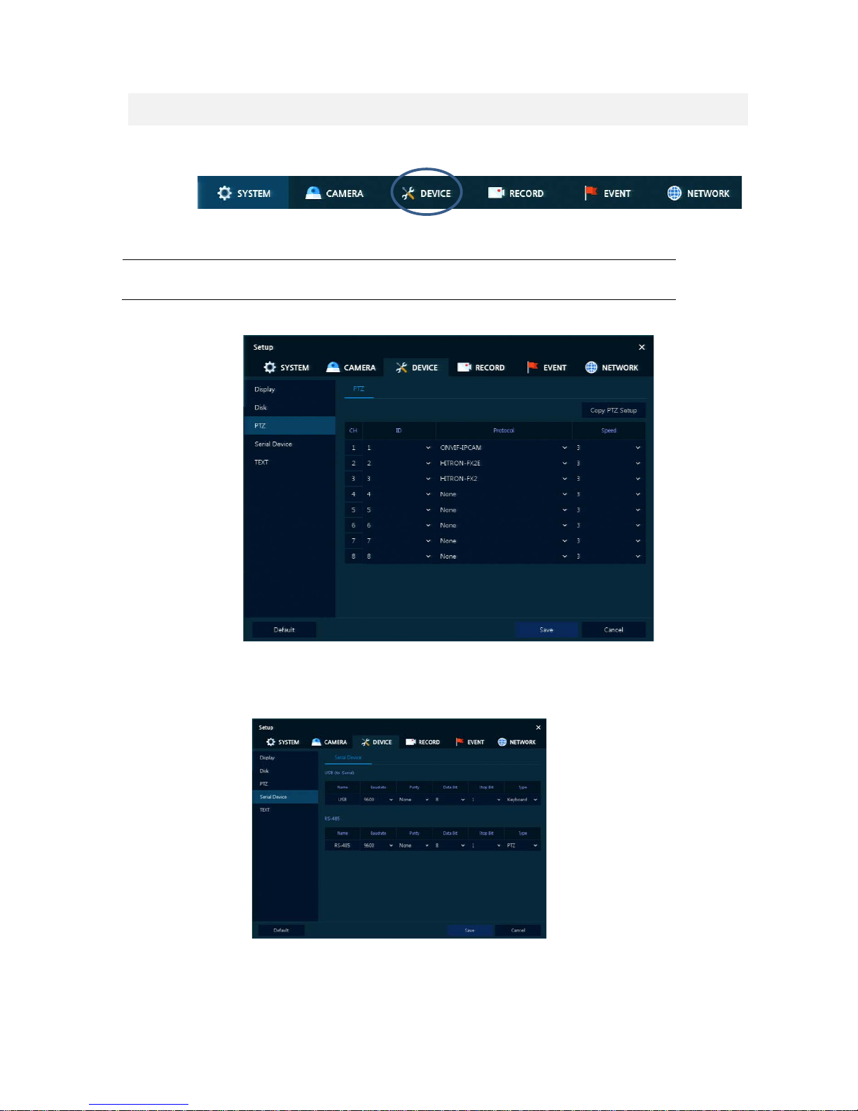
4. Setup menu
This chapter describes Setup menu at the top of the screen.
Figure 4-1 Setup menu
Selecting the menu opens the setting screen. To access the PTZ channels, select the Device tab.
Note
Setup screen is also available by selecting Setup in Quick menu, accessed by
clicking the right button of the mouse.
Select PTZ from the list on the left. The following screen displays.
To use PTZ Function of the device, users need to setup ID, protocol, and speed for each camera.
It is necessary to set a serial device to connect a PTZ camera. Select Serial Device from the list on the
left. Select RS-485, baud rate and PTZ type.
Page 14

For ofce locations, visit the website: www.vicon-security.com
VICON INDUSTRIES INC.
 Loading...