

Page 1
www.vicon-security.com
XX268-10-00
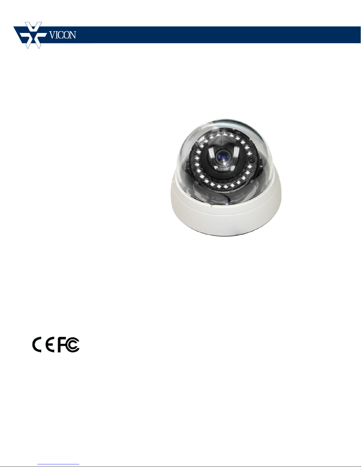
CE102D Network Indoor
Camera Dome
Vicon Industries Inc. does not warrant that the functions contained in this equipment will meet your requirements or that the
operation will be entirely error free or perform precisely as described in the documentation. This system has not been designed
to be used in life-critical situations and must not be used for this purpose.
Vicon Industries Inc.
Tel: 631-952-2288 Fax: 631-951-2288 Toll Free: 800-645-9116
24-Hour Technical Support: 800-34-VICON (800-348-4266) UK: 44/(0) 1489-566300
Document Number: 8009-8268-10-00
Product specications subject to change without notice.
Issued: 214
Copyright © 2014 Vicon Industries Inc. All rights reserved.
Quick Guide
Page 2

Page 3
Quick Installation Guide
1. Description
The information in this manual provides quick installation and setup procedures for the CE102D Series
of Camera Domes. These units should only be installed by a qualified technician using approved
materials in conformance with federal, state, and local codes. Read these instructions thoroughly
before beginning an installation. Always refer to Vicon’s website to assure you have the most up-todate manual, www.vicon-security.com
.
The CE102D-NIR HD IP Camera Dome is designed for indoor security installations. This cost-effective
fixed network camera includes an integral 3.7 mm megapixel fixed lens; the 1080p resolution delivers
crisp clear images. The CE202D-N cameras are fully compatible with all ViconNet® systems; its ONVIF
certification provides an open-platform for integration into other video management systems.
The network camera provides triple-streaming video and supports H.264 compression technology.
MPEG-4 and Motion JPEG (M-JPEG) compressions are also provided. Installation is made easy and
cost-effective with Power-over-Ethernet (PoE); the camera also accepts 12 VDC. The CE102D
automatically adapts to changing outdoor lighting; the true day/night camera includes a removable IR
cut filter. Built-in IR LEDs provide illumination up to 65 ft (20 m).
• Installation Steps
Follow these steps to install the network camera on your local network (LAN):
1. Check the package contents against the list below.
2. Connect the network camera
3. Set an IP address.
4. Set the password.
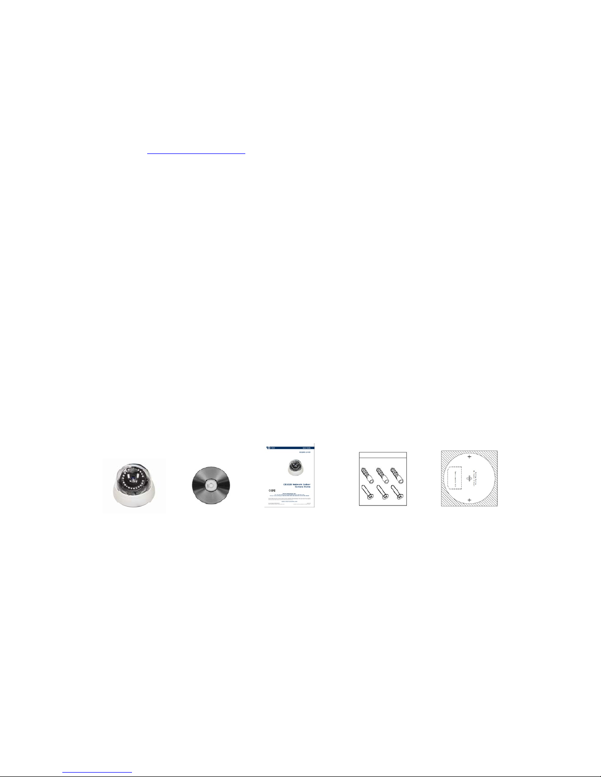
• Package Component
The system comes with the following components:
C
a
mera Unit Installation CD Installation Guide Accessory Kit Template sheet
Note: Adapter for 12 VDC is not supplied.
Check your package to make sure that you received the complete system, including all components
shown above.
• Contents in the installation CD
1. The CE102D-NIR User’s Manual
2. The SmartManager User’s Manual
3. The SmartManager Installation software
2
Page 4
Quick Installation Guide
2. Installation
2.1 Camera Installation
Carefully remove the contents from the box and verity that nothing was damaged in shipment.
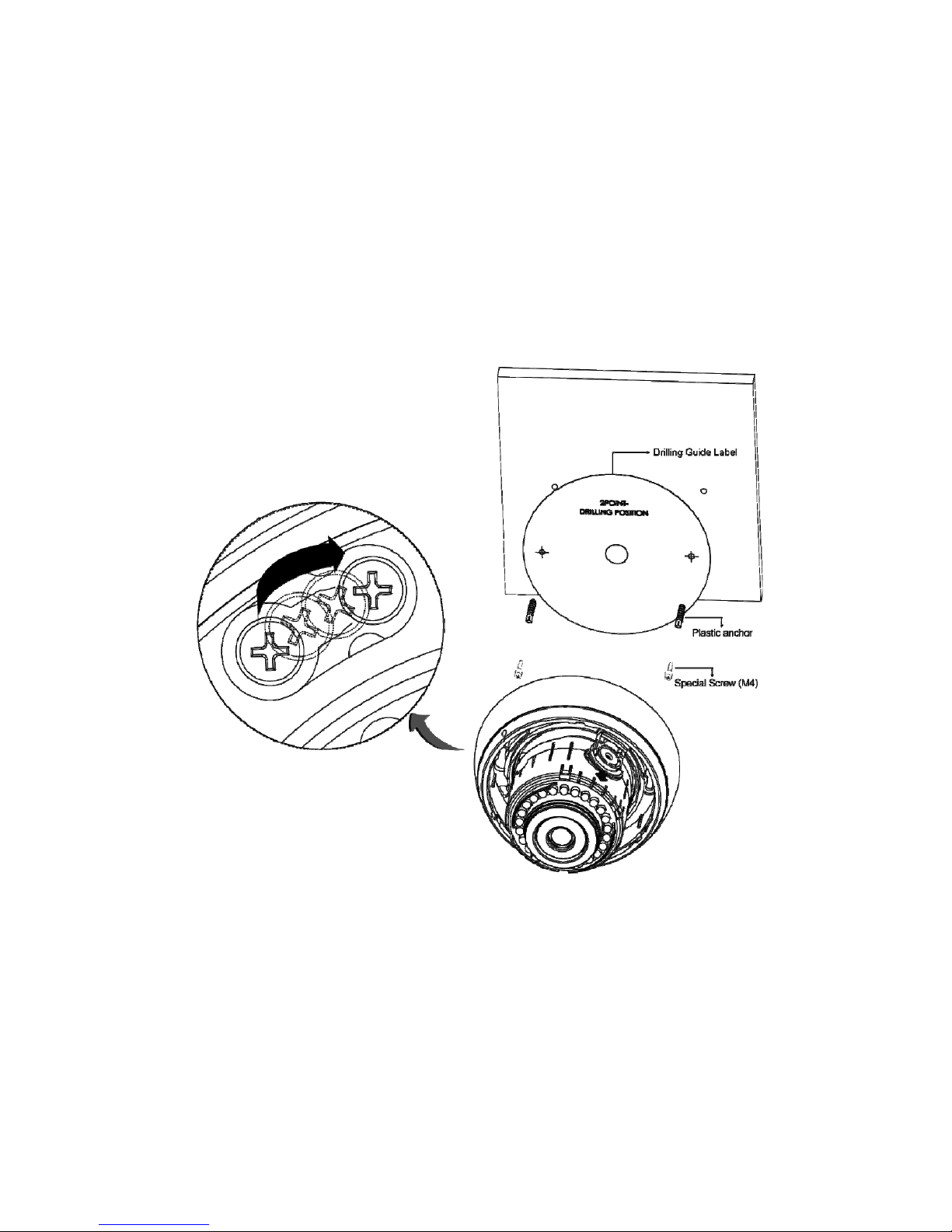
1) Using the template sheet provided, make screw holes for cam era on the ceiling.
2) Disassemble the camera by gently turning the camera cover counter-clockwise to remove it.
3) Secure the dome camera to the ceiling using the anchors (2x) and screws (2x) provided in the
accessory kit.
4) Reassembl
e
the dome cover to the camera assembly by aligning the notches. Turn Camera Cover
clockwise to complete installation. Secure the dome cover by using the locking screw provided in
the Accessory Kit.
3
Page 5
Quick Installation Guide
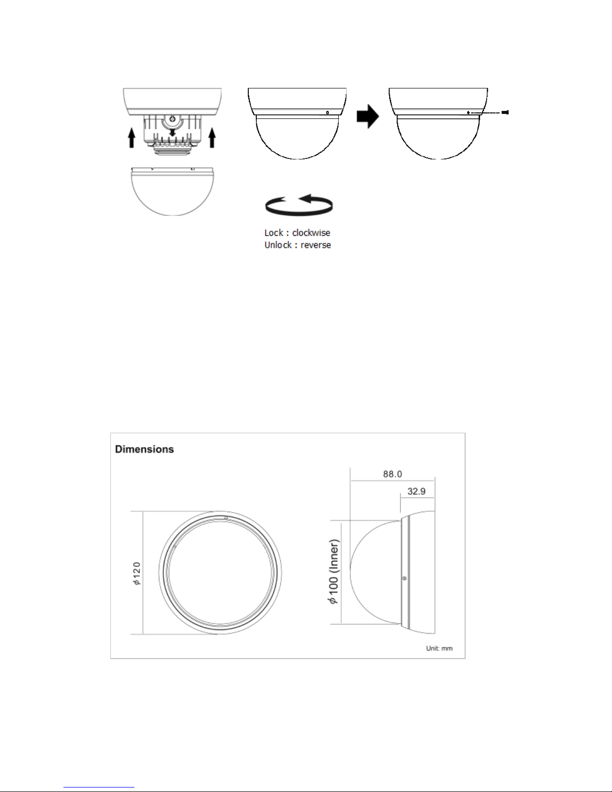
Locking Screw
Camera Dimension
See the diagrams below for the exact dimension
4
Page 6
Quick Installation Guide
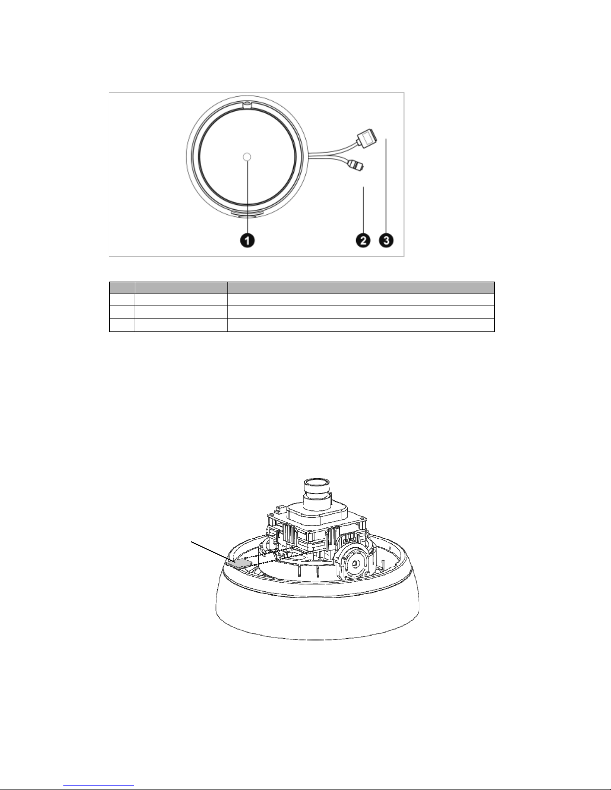
• Connection Cable
NO Name Description
1 Lens Allows wide area to be monitored
2 Power Cable
Cable for Power source (12 VDC )
3 Ethernet Cable
Cable for Ethernet (POE)
•
Connecting to the RJ-45
Connect a standard RJ-45 cable to the network port of the network camera. Generally a
cross-over cable is used for directly con nection to PC, while a direct cable is used for connection
to a hub or switch.
Micro SD memory slot
Insert the SD memory card (customer supplied).
SD memory card
•
Connecting
the Power
Connect a 12 VDC power adaptor (customer supplied) to the camera.
(This connection is not used if using PoE power.)
5
Page 7
Quick Installation Guide
2.2 Network Connection and IP assignment
The network camera is designed for use on an Ethernet network and requires an IP address for
access. Most networks today have a DHCP server that automaticall y assigns IP addresses to
connected devices. By the factory default, your camera is set to obtain the IP address automatically
via DHCP server. If your network does not have a DHCP server the network camera will use
192.168.1.100 as the default IP address.
If DHCP is enabled and the product cannot be accessed, run the “Smart Manager” utility on the CD to
search and allocate an IP address to your products, or reset the product to the factory default settings
and then perform the installation again.
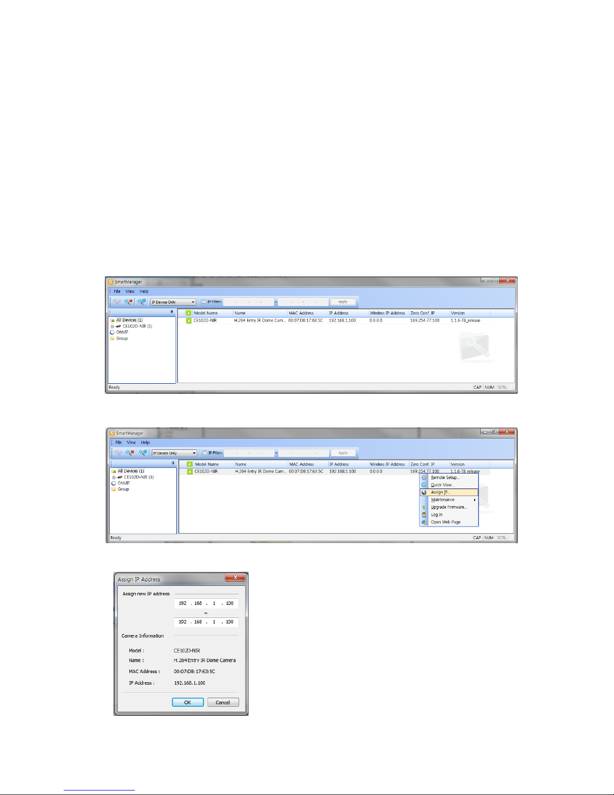
1. Connect the Network Camera / device to the network and power up.
2. Start SmartManager utility (Start>All programs>SmartManager>SmartManager), the main
window will be displayed, after a short while any network devices connected to the network will
be displayed in the list.
3.
Select the c
amera on the list and click right button of the mouse. The pop-up menu below
displays.
4
.
Select Assign IP. The Assign IP window displays. Enter the required IP address.
Note: F
o
r more information, refer to the Smart Manger
User’s Manual.
6
Page 8
Quick Installation Guide
3. Operation
The network camera can be used with Windows® operating system and browsers. The recommended
browsers are Internet Explorer®, Safari®, Firefox®, Opera® and Google® Chrome® with Windows.
Note: To view streaming video in Microsoft® Internet Explorer, set your browser to allow ActiveX
controls.
Note: Some screens may appear different (i.e., color scheme) depending on the firmware version, but
the functionality is the same or similar.
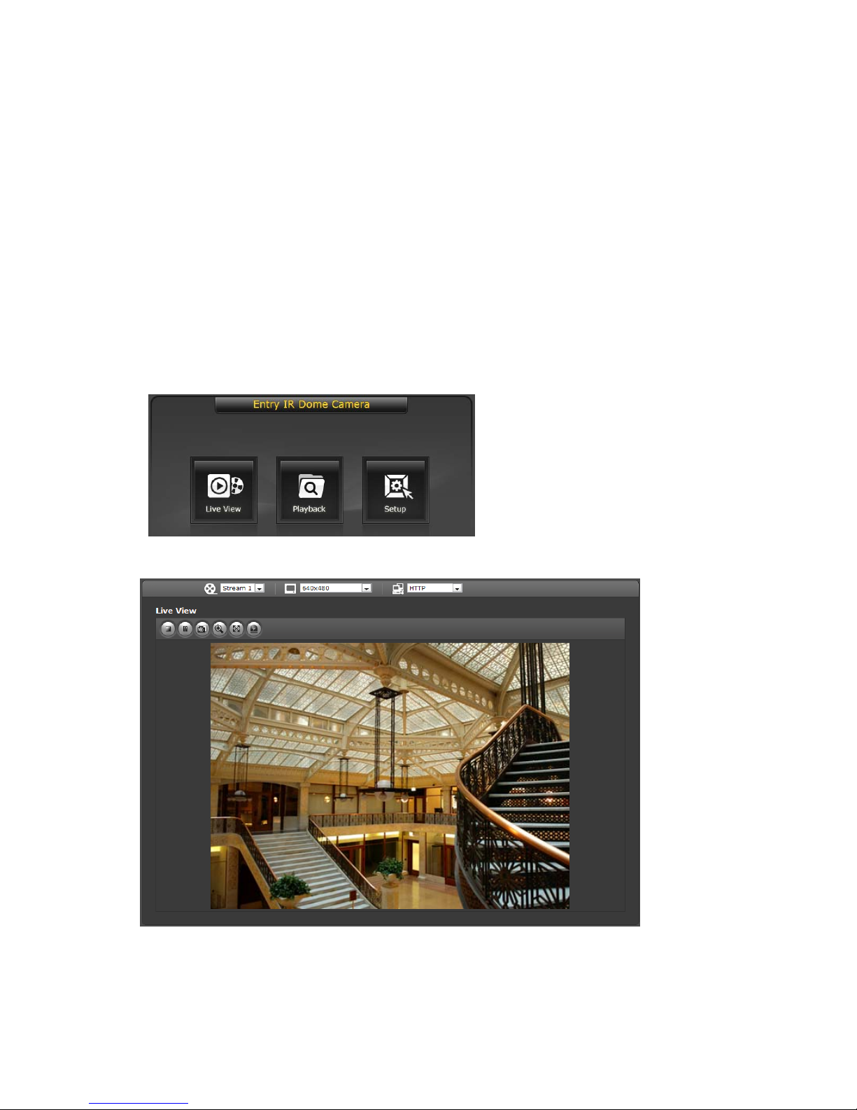
3.1 Access from a browser
1. Start a browser. (i.e., Internet Explorer).
2. Enter the IP address or host name of the Network Camera in the Location/Address field of your
browser.
3. You can see a starting page. Click Live View or Setup to enter web page.
4
.
Click Live View for the network camera’s Live View page to appear in the browser.
7
Page 9
Quick Installation Guide
3.2. Access from the internet
Once connected, the network camera is accessible on your local network (LAN). To access the
network camera from the Internet you must configure your broadband router to allow incoming data
traffic to the network camera. To do this, enable the NAT-traversal feature, which will attempt to
automatically configure the router to allow access to the network camera. This is enabled from Setup
> System > Network > NAT.
For more information, refer to “3.5.5 System>Network>NAT” of User’s Manual.
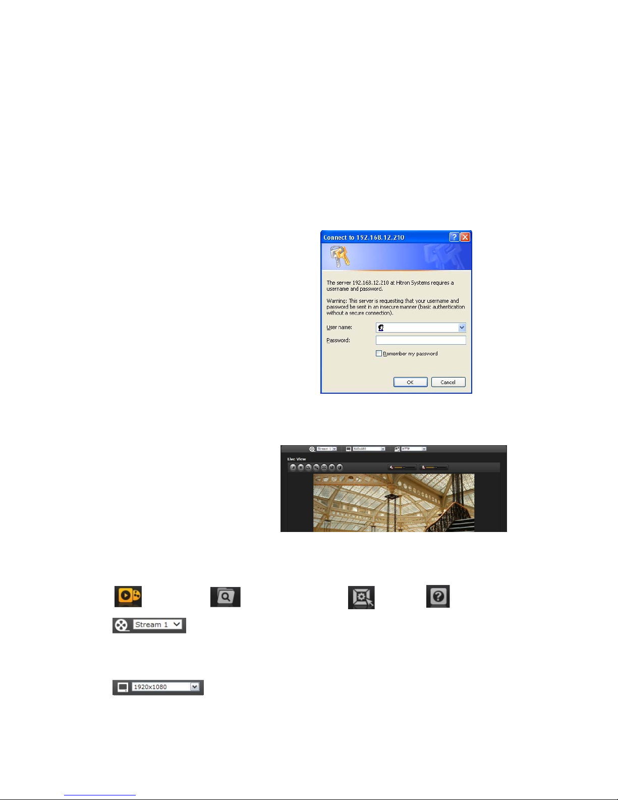
3.3 Setting the admin password over a secure connection
To g
ain access to the product, the password for
t
he default administrator user must be set. This
is done in the “Admin Password” dialo
g
, which is
displayed when the network camera
is accessed
f
or the setup at the first time. Enter your admin
name and password, set by the administrator.
Note: The default administrator username is
“
ADMIN” and password is “1234”. If the
password is lost, the network camera must be
reset to the factory default settin
g
s. See section
“
3.6 Resetting to the Factory Default Settings” for
more details.
3.4 Live View Page
T
he live view page comes in several screen
modes for example: 1920x1080,
1280x1024, 1280x720, 800x600, 704x480
(576), 640x480, 352x240 (288) and
320x240. Select the most suitable mode in
accordance with your PC specifications and
monitorin
g
purposes.
1) General controls
Live View Page Search & Playback Page Setup Page Help Page
The video drop-down list allows you to select a customized or pre-programmed
video stream on the live view page. Stream profiles are configured under Setup > Basic
Configuration > Video & Image. For more information, see section “3.5.1 Basic Configuration >
Video & Image” of User’s Manual.
T
he resolution drop-down list allows the selection of the most suitable video
resolution to be displayed on Live View page.
8
Page 10
Quick Installation Guide
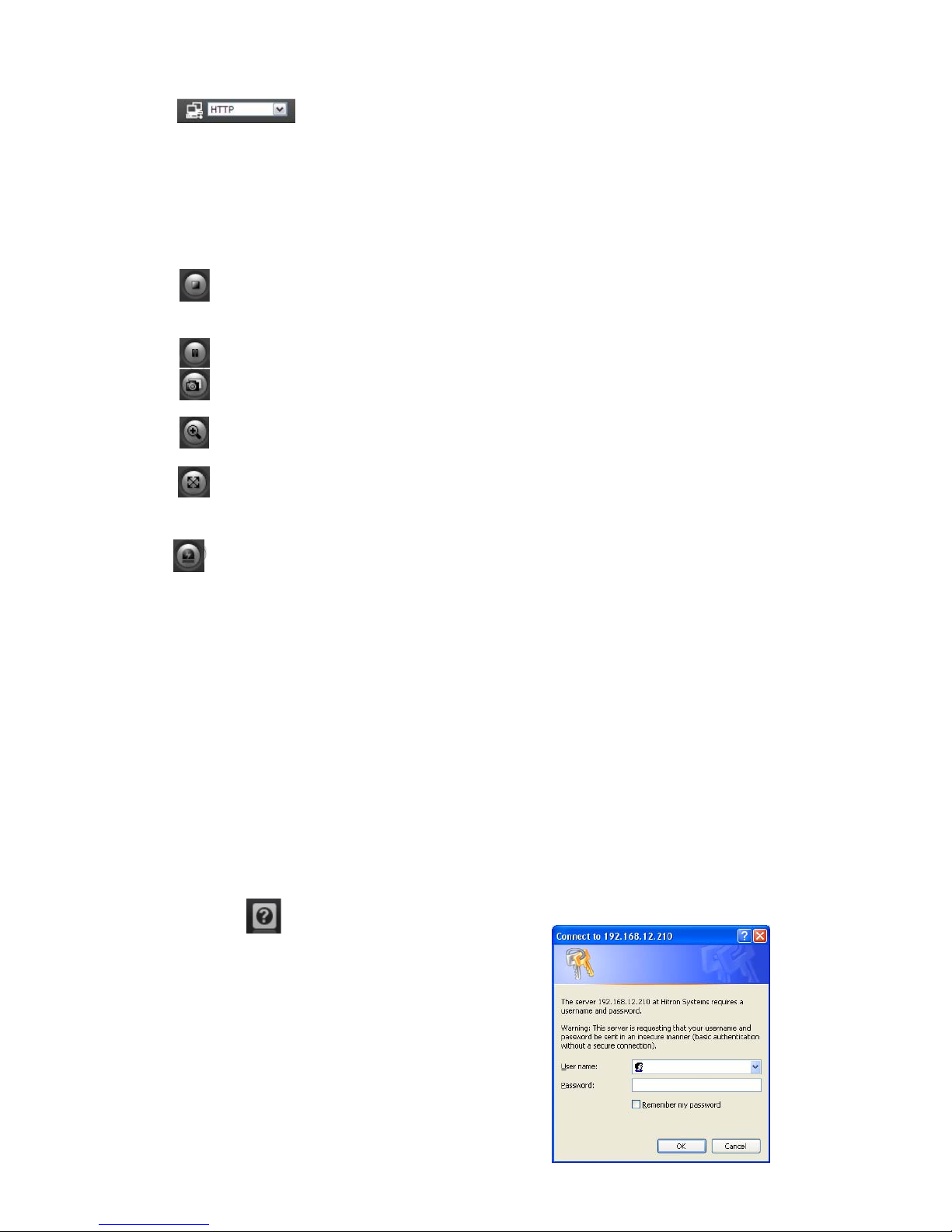
The protocol drop-down list allows the selection of the combination of protocols
and methods to use depending on your viewing requirements and on the properties of your
network.
2) Control tool
bar
The live viewer toolbar is available in the web browser page only. It displays the following
buttons:
The Stop but
ton stops the video stream being played. Pressing the key again toggles the
start and stop. The Start button connects to the network camera or start playing a
video stream.
The Pause button temporar ily stops (pauses) the video stream being played.
The Snapsh
ot button takes a picture (snapshot) of the current image. The location where
the image is saved can be specified.
The digital zoom activates a zoom-in or zoom-out function for video image on the live
screen.
The Full Scr
een button causes the video image to fill the entire screen area. No other
windows will be visible. Press the 'Esc' button on the computer keyboard to can cel full
screen view.
The Manual T
rigger button activates a pop-up window to manually start or stop the event.
3) Video Streams
The network camera provides several images and video stream formats. Your requirements and
the properties of your network will determine the type you use.
The Live View page in the network camera provides access to H.264, MPEG-4 and Motion JPEG
video streams, and to the list of available video streams. Other applications and clients can also
access these video streams/images directly, without going via the Live View page.
3.5 Network Camera Setup
This section describes how to configure the network camera, and is intended for product
Administrators, who have unrestricted access to all the Setup tools; and Operators, who have access
to the settings for Basic, Live View, Video & Image, Event, and System Configuration.
You can configure the network camera by clicking Setup in the top right-hand c orner of the Live View
page. Click on to access the online help that explains the setup tools
When
acc
essing the network camera for the first time, the
“Admin P assword” dialog appears. Enter your admin name
and password, set by the administrator.
Note: If the password is lost, the network camera must
be reset to the factory default settings.
See “3.6 Resetting to the Factory Default Settings”.
9
Page 11
Quick Installation Guide
3.6 Resetting to the factory default settings
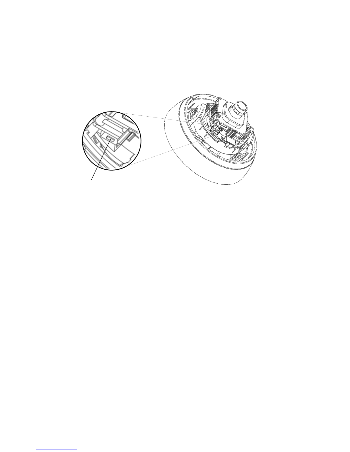
To reset the network camera to the original factory settings, go to the Setup>System> Maintenance
web page (described in “3.5.5 System > Maintenance”) or use the Reset button on the network
camera, as described below.
Reset Button
•
Using the Reset Button
Follow the instructions below to reset the network camera to the factory default settings using
the Reset button.
1. Power off the network camera by disconnecting the power adapter.
2. Remove lower dome if not already done so.
3. Press and hold the Reset button while reconnecting the power.
4. Keep the Reset button pressed for at least 2 seconds.
5. Release the Reset button.
6. The network camera resets to factory defaults and restarts after completing the factory
reset.
7. Reattach the dome.
Caution: When performing a Factory Reset, you will lose any settings you have saved.
3.7 More Information
For more information, refer to the network camera User’s Manual, which is available on the CD
included in this package.
10
Page 12

CE102D Network Indoor Camera Dome
50303747A
Vicon Industries Inc.
Internet Address: www.vicon-security.com
 Loading...