

Page 1

Valco Instruments Co. Inc.
2 Position
Electric Actuator
Instruction Manual
P. O. Box 55603, Houston, TX 77255
(713) 688-9345
•
Sales toll-free (800) 367-8424
Fax (713) 688-8106
MAN-2EA
Rev. 9/12
Printed in USA
Page 2

Table of Co ntents
1. GENERAL DESCRIPTION............................................................................... 1
2. MANUAL USE OF THE 2 POSITION VALVE ACTUATOR .............................. 2
3. CONTROLLING THE ACTUATOR WITH A COMPUTER................................3
3.1 Using a Relay Output
3.2 Using a Logic Level Output
3.3 Using the Output from the Actuator
3.31 Inject Contact Closure
3.32 Positive Position Feedback
4. INSTALLING A VALVE ON AN ACTUATOR....................................................5
4.1 Preparing a M anual Valco Valve for Mounting on an Actuator
4.11 Disas sembly of a Manual W or UW Type Valve
4.12 Removing the Handle or Knob from a Valve on a Standoff
4.13 Removing the Handle f rom a P Type Valve
4.14 Removing the Handle from a U Type Valve
4.2 Installation of a Valve With Closemount Hardware
4.3 Installation of a Valve With a Standoff
5. VALVE ALIGNMENT.......................................................................................11
5.1 Visually Checking the Alignment
5.2 Chromatographic Symptoms of Misalignment
5.21 Loss of Flow or Blocked Flow
5.22 Multiple Peaks or Doublets
5.3 Causes of Misalignment
5.31 Removal of the Valve from the Actuator for Mounting
5.32 Shock from Heavy or Continuous Use
5.4 Alignment Procedure
6. ACTUATOR MODIFICATIONS ....................................................................... 14
6.1 Adjusting the Actuator Stroke
6.2 Actuator Conversion
6.21 Disassembly
6.22 Installation of the New Crank Assembly
6.23 Flag Adjustment
7. TECHNICAL DRAWINGS...... .. .. .. .. .... .. .. .. .. .. .. .. .. .. .. .. .. .. .. .. .. .. .. .... .. .. .. .. .. .. .. .. .. .. .20
8. WARRANTY............... .. .. .. .... .. .. .. .. .. .. .. .. .. .. .. .. .. .. .. .. .. .. .... .. .. .. .. .. .. .. .. .. .. .. .. .. .. .. .. .. .25
Page 3

1. GENERAL DESCRIPTION
Valco 2 position valves are widely used in a variety of sample injection and
switching applications. Rotating them to the desired position can be done
manually, but is best done automatically with either the Valco 2 Position Air
Actuator or the Valco 2 Position Electric Actuator described in this manual. For
most laboratory uses, especially where a laboratory computer is available for
contr ol bu t com pres sed a ir i s not , t he Valco 2 Position Elec tri c A ctua tor i s th e be st
choice.
Valco 2 Position Ele ctric Ac tuators are available in 110VAC or 220VAC models for
any 30° , 36 °, 45° , 60 °, or 90 ° Valco valve. The mod el n umb ers o f t he act u ato rs ar e
respectively E30, E36, E45, E60, and E90. (Or E30-220, etc.) An electric actuator
can be retrof itted to ex isting a ir actuate d or manu al valves and i s compat ible with
all Valco close coupling and standoff assembly hardware.
The 2 position electric actuator is a complete system, with all the necessary cables
and power cord. It consists of (a) the actuator itself, (b) a control box with LED
display, and (c) an interface cable for remote switching. The actuators are normally
suppli ed w ith a mot or/ gear train tha t moves t he val ve from Position A to Position B
in 0.56 seconds. All electric actuator models use separate line voltages (120V AC
or 220V AC, 50/60 Hz) and require no power from the chromatograph with which
they ar e u se d.
1
Page 4
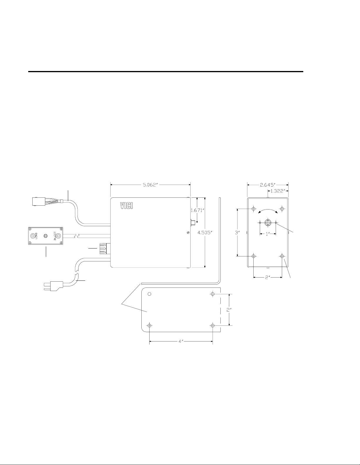
2. MANUAL USE OF THE
2 POSITION VALVE ACTUATOR
The electric actuator has a control box with a two-position, spring-loaded (normally
off) toggle switch and two LED’s which indicate the valve position. The valve can
be moved from one position to the other by manually moving the toggle switch
toward the light that is not illuminated.
REMOTE SWITCHING CABLE
(WITH 5 FOOT EXTENSION)
Valco Instruments Co. Inc.
POS B
(INJECT)
POS A
(LOAD)
HOLES FOR
CLAMP RING
SCREWS
CONTROL BOX AND
CABLE (4 F E ET )
2 AMP F USE
POWER CORD (5 FEET)
MOUNTI N G B R ACKE T
Figure 1:
Actuator dimensions
8-32 MOUNTING HOLES
(FOUR PLACES)
2
Page 5
3. CONTROLLING THE ACTUATOR
WITH A COMPUTER
The remote switching cable is used to communicate a momentary or continuous
contact closure or a negative true logic level signal from a data system, required
for automated operation of the actuator. In addition, two of the cable’s leads
supply feedback from the actuator. Since the input signal must be of 10 to 20
milliseconds duration to switch the actuator, a sub-millisecond noise spike will not
start the actuator.
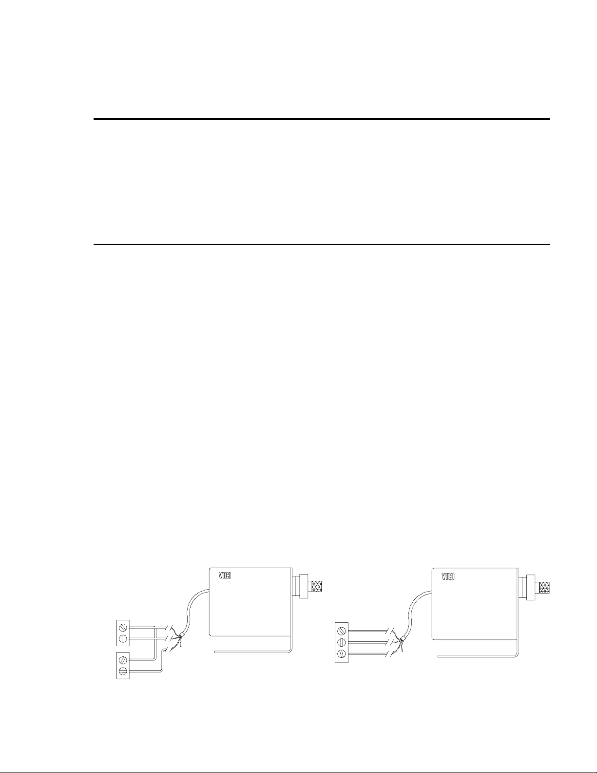
3.1 Using a Relay Output
If the data system has two relays available, then one relay can be dedicated to
each position of the actuator. This is ideal, since it allows the manual switch to
function normally. Connect the black wire (INJECT) to the normally open (NO)
terminal of the first relay and the the green wire (GROUND) to its common or logic
ground ter min al. Connect the r ed wi re ( LOAD) t o the nor mally open (NO) t er mina l
of the second relay, and connect a jumper wire from the common or logic ground
of the first relay to that of the second. (
Program the data system to energize the first relay when the valve is to be
switched to t he I N JEC T po s iti on , le avin g i t en er gi zed for only t wo o r th ree se con ds.
Likewise, at the time for LOAD, turn on the second relay for a few seconds. The
INJECT relay must be turned off before the LOAD relay is turned on, and vice
versa. If the valve will not move out of a position, it is most likely that the relay
which switched it to that position has not been turned off. When n either rel ay is
energized, the manual toggle switch can be used as described on the previous
page.
Figure 2
)
RELAY 1
GND
NO
GRD
NO
RELAY 2
GREEN
BLACK
RED
Figure 2:
If the data system has only a single double-pole relay with normally open (NO)
and normally closed (NC) terminals (
Figure 3
), connect the green wire (GROUND)
to the relay common or logic ground. Connect the black (INJECT) wire to the
normally open (NO) relay terminal and the red (LOAD) wire to the normally closed
(NC) terminal. The computer must be programmed to keep the Normally Open
(NO) relay contact engaged (ON) as long as the actuator is to be in the INJECT
position.
GREEN
GND
Dual relay connection
NO
NC
BLACK
RED
Figure 3:
Single relay connection
3
Page 6

3.2 Usi ng a Logic Level Output
If the data system uses negative true logic level output, connect the green wire
(GROUND) to the Logic Ground of the data sy stem relay. Connect the red wire
(LOAD) t o on e out put of the re lay and the bla ck wir e (INJ ECT) to th e othe r out put.
Turning the relay off will switch the actuator to LOAD and turning it on will switch it
to INJECT. If the operations are reversed, simply switch the connection of the red
and black wires.
3.3 Using the Outp ut from th e Actuator
The whi te and cl ear wires can perform either of two func tions, depen ding on the
setting of the dipswitch on the circuit board. The factory setting is for the Inject
Contact Closure mode.
3.31 Inject Co ntact Closure
In this mode, which is the factory default, the white and clear wires provide a
conta ct closur e when the ac tuator moves to the INJ ECT positio n. (The closure is
approximately two seconds long.) It may also be used to "spike" a recorder or to
start a ny d evice eq uipp ed wi th a r emo te c on t act c los ur e in pu t.
3.32 Positive Position Feedback
To change t he setti ng on th e dipswitc h, follow St eps 1-4 in Sectio n 6.21,
Conversion, Di sassem bly
for the ma nual switch ing cable. (See Draw ing 21312 , page 23. ) In this mod e, the
clear w ire carr ies a logic hi gh when the ac tuator is in the Posi tion A (LOAD) : the
white wire carries a high when the actuator in is Position B (INJECT).
. The dipswitc h is on th e boa rd next to the conn ection s
Actuator
4
Page 7
4. INSTALLING A VALVE ON AN ACTUATOR
4.1 Pr eparin g a Ma nual Valco Valve for Mo unting on an Actu ator
A manually switched 2 position valve has a handle or knob which must be removed before the valve can be installed on the actuator. Sections 4.11 - 4.14
describe the procedures for various Valco valves.
4.11 Disassembly of a Manual W or UW Type Valve
1. Rotate the knob counterclockwise so the valve is positioned properly for
later installation on the electric actuator.
HWSC-SS8-5B/
SET-SCREW
WK/KNOB
HWSC-SC8-16
SCREWS
2. See
Figure 4
. Loosen the set-screw within the W valve knob and pull the
knob off of the manual drive shaft.
3. Using a 9/64 hex driver, unscrew the two HWSC-SC8-16/socket head
screws (8-32 x 1") until the valve comes loose from the rest of the assembly.
Keep the driver with the valve.
4. The rest of the assembly will slide easily apart, but you may wish to keep it
together for future use.
5. Proceed to Section 4.2 for c losemount assembly, or Sec tion 4.3 if the valve
will go on a standoff before being installed on the actuator.
KNOB ASSEMBLY
WSB/SHAFT
BEARING
PLATE
Figure 4:
WSH/SHAFT HOUSING
STANDARD
ANGLE
BRACKET
WDS/MANUAL
DRIVE
SHAFT
FLAT
FACE
W or UW type valve with knob assembly
WD/DRIVER
ROTOR
PIN
COLLAR
CUTOUT
VALVE
BODY
PRE-LOAD
ASSEMBLY
4.12 Removing th e Hand le or K nob from a Valve on a S tandof f
1. Rotate the knob counterclockwise so the valve is positioned properly for
later installation on the electric actuator.
2. See
Figure 5
. Simply pull the handle or knob, with the manual handle
adapter and retainer, off of the standoff tube.
3. Proceed to Section 4.3.
5
Page 8
KNOB ASSEMBLY
STANDOFF ASSEMBLY (Length varies)
WITH VALVE ATTACHED
HWSC-SS8-5B/
SET-SCREW
WK/KNOB
RETAINER
MHA/MANUAL
HANDLE
ADAPTER
FLAT FACE
Figure 5:
HWSC-SC6-8B/
SCREW
SCREWS
FOR CR2
(NOT SUPPLIED)
Manual valve on a standoff
STANDOFF
OPTIONAL
MOUNTING
BRACKET OR
OVEN WALL
4.13 Removing the Handle from a P Type Valve
These types of valves have a 1-1/8" metal rotor shaft that connects to the handle.
1.Rotate the knob counterclockwise so the valve is positioned properly for
later installation on the electric actuator.
2.See
Figure 6
. Remove the black handle by sliding its shaft out of the
coupling.
3.Place the coupling in a bench vise with the side with only one hole facing
up. Use a hammer and punch to remove the roll pin which connects the
coupling to the valve rotor shaft. Pull the coupling off of the shaft.
PRE-LOAD
ASSEMBLY
VALVE
BODY
CAUTION: Do not hold the valve body in the vise when removing t he
coupling. Valve damage will result.
4.Proceed to Section 4.2 for closemount assembly, or S ection 4.3 if the valve
will go on a standoff before being installed on the actuator.
HANDLE ASSEMBLY
ROTOR
PIN
HWSC-SS10-3B/
SET-SCREW
SVH/
STANDARD
HANDLE
FLAT
FACE
Figure 6:
ROLL
PIN
SHAFT
COUPLING
P Type valve with an SVH handle
(Varies with valve type)
CUTOUT
SPRING HARDWARE
VALVE
BODY
6
Page 9
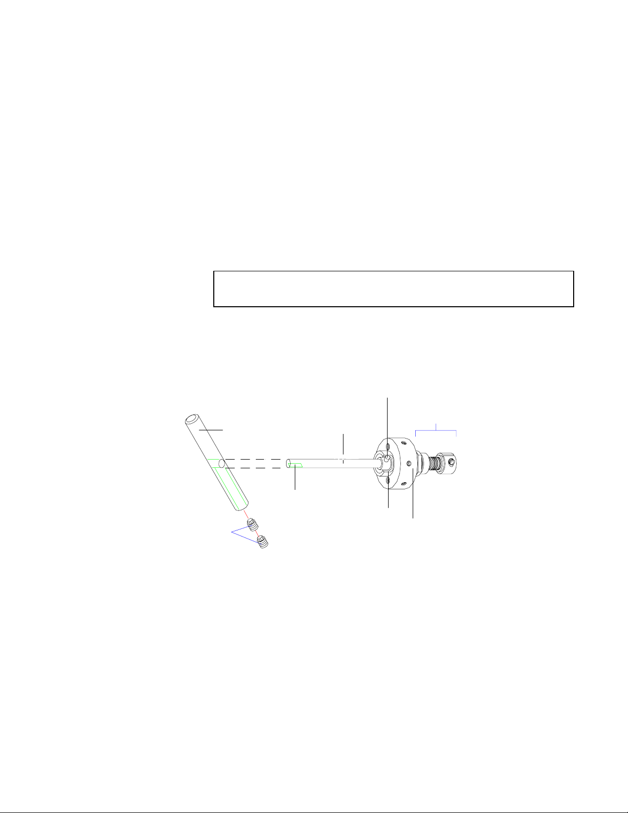
4.14 Removing the Handle from a U Type Valve
In addition to removing the handle, it is necessary to cut the 3" shaft of the manual
U Type valve to ap proxim at el y 1" .
1. Rotate the knob counterclockwise so the valve is positioned properly for
later installation on the electric actuator.
2. See
two
Figure 7
set screws within the handle.
. Remove the handle by using a 1/8 hex driver to unscrew the
3. Take all the fittings out of the valve. Cover all the ports with mas king tape
so that no debris can enter the ports.
4. Clamp the end of the shaft,
not the valve body
, in a bench vise. Carefully
cut the valve shaft to a length of 1" or less with a hack saw. Be sure not to
let the valve fall and become damaged.
CAUTION: Do not ho ld the val ve b ody in th e v ise wh en c ut ti ng the
shaft. Valve damage will result.
5. Proceed to Section 4.3.
ROTOR P IN
SPRING HARDWARE
UHT/
HANDLE
SHAFT
(Varies with valve type)
HWSC-SS1/4F-4B
SET-SCREWS
FLAT FACE
Figure 7:
CUTOUT
VALVE
BODY
U Type valve with UTH handle
7
Page 10

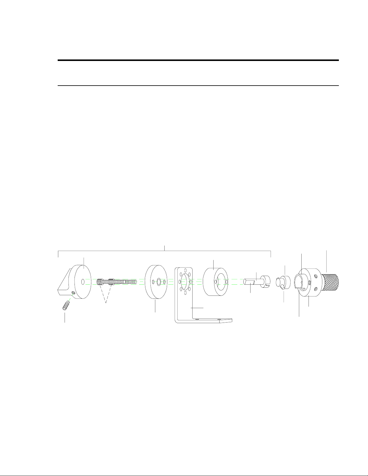
4.2 Installation of a Valve With C losemount Hardware
If the electric actuator has been specified for use with closemount hardware, it will
be received from the factory with the CR4/clamp ring already affixed to the
actuator. The clamp ring is attached to the actuator with a two HWSC-SC86TDH/modified socket head screws (8-32 x 3/8").
CAUTION: Do not use screws longer than 1/2" to attach clamp rings to
electric actuators. They will interfere with internal moving parts and
damage the actuator.
1.Plug in the electric actuator and put it into the LOA D position (indicated by a
red light in the LOAD position) on the control box. The valve will have been
rotated to the counterclockwise position before the knob or the handle was
removed, so they should now be in the same relative rotational position.
CAUTION: The valve and the actuator must be in corresponding
rotational positions before assembly. If they are not, t he valve or
actuator may be damaged when operated.
2.Place the slotted coupling over the driver (
(
Figure 6 and 7
) and engage the rotor pin.
Figure 8
) or the valve shaft
3.The actuator is shipped with the CR41/closemount standoff mounted in the
CR4/clamp ring. Remove the CR41 from the CR4 and attach it to the valve
body with the two HWSC-SC6-10NT/modified socket head screws (6-32 x
5/8"). (Only one is used for a P-Type 10 port valve.) The CR41 must be
oriented so that the valve cutout is visible through the long slot on its side.
4.Press the flange of the CR41/closemount standoff into the CR4/clamp ring
on the actuator, making sure that the square driver of the actuator engages
the squared hole of the slotted coupling. (It may be eas ier to put the slotted
CLOSEMOUNT STANDOFF
PRE-LOAD
TAB
ASSEMBLY
VALVE
BODY
SQUARE
DRIVER
CR4/
CLAMP
RING
HWSC-SC6-8B/
SCREW
HWSC-SC8-12TDH/
SCREWS
CR41/CLOSEMOUNT
STANDOFF
SLC/SLOTTED-
COUPLING
ROTOR
PIN
WD/DRIVE
CUTOUT
ROTOR
HWSC-SC6-10NT/
SCREWS
Figure 8:
Valve on actuator with closemount hardware
8
Page 11

coupling on the square driver of the actuator first. However, make sur e that
the driver doesn’t get cocked.) The CR41/closemount standoff should end
up flush against the CR4/clamp ring.
5.Tighten the HWSC-SC6-8B/screw (6-32 x 5/8") in the clamp ring with a
7/64 hex driver.
6.Align the valve and actuator according to the
in Section 5.4.
CAUTION: If the valve and actuator are not properly aligned, the slots
on the valve rotor and the ports in the valve body will not align properly.
The flow of sample may be blocked, and other problems may result.
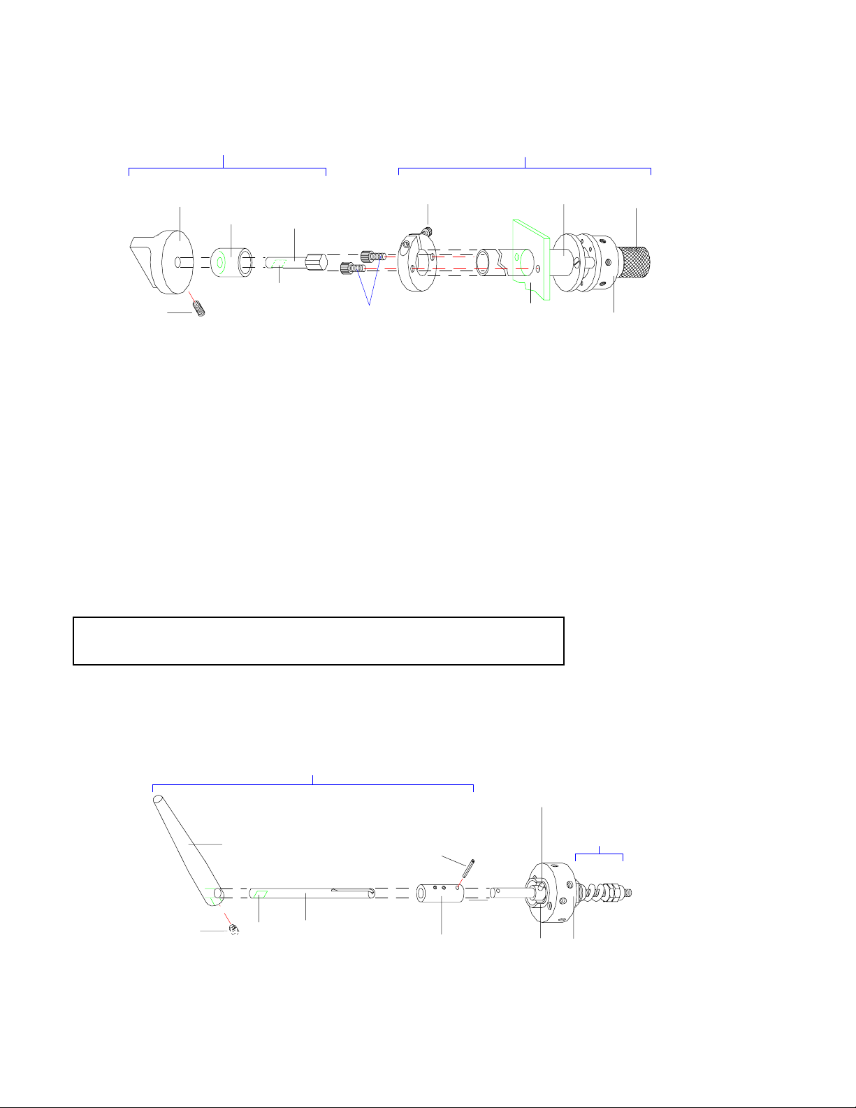
4.3 Installation of a Valve With a S tandoff
If the electric actuator has been specified for use with a standoff, it will arrive from
the factory with the CR3/clamp ring already on the actuator. The clamp ring is
attached to the actuator with two HWSC-SC8-8B/socket head screws (8-32 x 1/2") .
CAUTION: Do not use screws longer than 1/2" to attach clamp rings to
electric actuators. They will interfere with internal moving parts and
damage the actuator.
1.Plug in the electric actuator and put it into the LOA D position (indicated by a
red light in the LOAD position) on the control box. The valve will have been
rotated to the counterclockwise position before the knob or the handle was
removed, so they should now be in the same relative rotational position.
CAUTION: The valve and the actuator must be in corresponding
rotational positions before assembly. If they are not, t he valve or electric actuator may be damaged when operated.
Alignment Procedure
found
HWSC-SC8-8B/
SQUARE
DRIVER
CR3
CLAMP
RING
SCREW
HWSC-SC8-8B/
SCREWS
SCREWS
(NOT
PRO-
Figure 9:
STANDOFF ASSEMBLY (Lengths vary)
HWSC-SC6-8B/
SCREW
CR2/
CLAMP
RING
STANDOFF
OPTIONAL
MOUNTING
BRACKET
OR OVEN WALL
Valve on actuator with a standoff
STANDOFF
DRIVE SHAFT
CUTOUT
ROTOR
PIN
WD/DRIVER
ROTOR
TAB
PRE-LOAD
ASSEMBLY
VALVE
BODY
HWSC-SC6-
10NT/
9
Page 12

2. Remove the CR2/clamp ring from the standoff and mount it on the oven
wall. (Screws are not provided for this pur pose.) Slide the standoff through
the CR2/clamp ring on the oven wall or bracket. (The standoff requires an
11/16" clearance hole.)
3. Firmly press the end of the st andoff into the CR3/clamp ring mounted on the
actuator, making sure that the square driver of the actuator engages the
squared hole of the standoff drive shaft. Position the entire assembly so
that the entire valve body cutout is visible.
4. Tighten the screw in the CR3/clamp ring.
5. Align the valve and actuator according to the
in Section 5.4.
CAUTION: If the valve and actuator are not properly aligned, the slots
on the valve rotor and the ports in the valve body will not align properly.
The flow of sample may be blocked, and other problems may result.
7. Position the standoff in the CR2/clamp r ing and tight en the clamp ring screw
to secure the standoff in place.
Alignment Procedure
found
10
Page 13

5. VALVE ALIGNMENT
When the valve arrives from the factory installed on the actuator, it is accurately
aligned and ready to use. However, every time the clamp ring on the actuator is
loosen ed to re adjust or remove the va lve from th e actuat or, the valve and actu ator
alignment
rotor al ign pro pe r ly.
5.1 Vis ually Checking the Alig nment
It is important to note that the actuator actually drives only the rotor within the
valve body, and that the valve or valve/standoff assembly remain stationary with
respect to the actuator. To check the alignment, cycle the actuator from one
position to the other and observe the location of the rotor pin. The rotor pin should
come to rest against both sides of the cutout in the valve body.
show th e rotor pi n in both po sitions ( LOAD and IN JECT). In
pin contacts one side of the c utout but does not touch the other side, indica ting
that the valve needs to be aligned. (See Section 5.4,
Figure 11
actuator stroke must be adjusted. (See Section 6.1,
.)
Stroke
be checked to be sure that the internal ports and slots on the
must
, the pin does not touch the cutout on either side, indicating that the
Figure 12
shows the pin properly contacting both sides of the cutout.
Figures 10-12
Figure 10
, the rotor
Ali gnment Proced ure
Adjusting the Actuator
.) In
END OF ROTOR PIN
IN EITHER POSITION
CUTOUT
VALVE
BODY
Figure 10
Adjust alignment
END OF ROTOR PIN
IN EITH E R PO S IT IO N
CUTOUT CUTOUT
VALVE
BODY
END OF ROTOR PIN
IN EITHER POSITION
Figure 11
Adjust stroke
Proper al ig nme nt
VALVE
BODY
Figure 12
11
Page 14

5.2 Chromatographic Symptoms of Misalignment
5.21 Loss of Flow or Blo cked Flow
When the rotor does not rotate completely or accurately, the ports of the valve may
not intersect the engravings on the valve rotor. This can cause a loss of flow at
outlet s or a blockag e of flow at inlets .
5.22 Multipl e Peaks or Doublets
In some configurations, the engraving may not be aligned properly even though
flow is not eliminated. Some engravings are very small or very large, and
inaccu rate alignment can cause what appear to be multiple injections due to the
sweeping action of the rotor.
5.3 Caus es of Misalig nment
5.31 Removal of th e Valve from the Act uator for M ounti ng
To mount valv es throu gh a bracket or oven wall , the val ve and stan doff asse mbly
must be separated from the actuator. Any time the clamp ring screw has been
loosened, the alignment of the valve after replacement on the actuator
checked, an d r ea li gned as ne ce ssa r y.
must
be
NOTE: To reduce the possibility of having to realign after installation,
before removing the valve from the actuator:
Closemount:
where it lines up with the slot in the stainless clamp ring on the actuator.
Standoff:
lines up wit h the sl ot in t he bla ck anod ize d c la mp r i ng on t h e ac tu ato r. Do
not remove the valve from the standoff assembly.
When t hi s ma r k i s l in ed up w it h t he sl ot on re ass embly, the fact or y ali gn men t
will be approximately reproduced as long as the valve and the actuator remain i n th ei r o r ig inal po si tio ns.
Whenever the valve and standoff assembly is removed from the actuator and
replaced, be certain that the assembly is inserted into the actuator as far as
possible (approximately 3/8 inch) to achieve complete driver coupling.
5.32 Shock from Heavy or Conti nuous Use
Occasionally, when valves are used in applications requiring a high-duty cycle,
wear or shock may cause the valve mounting screws or the clamp ring screw to
loosen . This al lows the valve to overth row and may resul t in misalig nment. The
most obvious symptom is movement observed in the valve or valve/standoff
assembly, which normally would not move when the valve is actuated.
Make temporary registration marks on the face of the valve
Make t emp ora r y reg is t rati on mar ks on t he s t an dof f tub e wher e i t
12
Page 15

5.4 Alignment Procedure
1. After determining that alignment is necessary, actuate the valve to the
position in which the rotor pin is against the stop.
2. Loosen the clamp ring screw slightly. This will allow the actuator to complete
its travel if it was being stopped by the end of the valve rotor travel. The
valve body will rotate slightly.
3. Tighten the clamp ring screw and cycle the actuator to the other position.
The pin should come to rest against the stop. If it does not, repeat the
procedure. If after several attempts the pin still does not contact the stop in
both positions, see Section 6.1,
Adjusting the Actuator Stroke.
13
Page 16

6. ACTUATOR MODIFICATIONS
6.1 Adjusting the A ctuator Stroke
If for any reason the actuator will not rotate the valve rotor completely, or if you
have reason to believe that the actuator is stroking too far, refer to the direc tions
below to adjust the actuator for slightly more or less rotation than is supplied by
the factory.
Because of differing amounts of play designed into the com ponents, the actuator
stroke
different mounting hardware than it originally received at the factory: i.e., a standoff
assembly used with an actuator that originally had closemount hardware, or
closemount hardware used with an actuator originally supplied with a standoff
assembly.
Valve alignment should always be checked before adjusting the actuator stroke to
confirm that the rotor pin is not contacting either side of the cutout. Since it is
difficult to see whether the stroke is too great, adjust the stroke by very small
increments so that you can stop as s oon as the rotor pin just contacts both s ides
of the cutout.
NOTE: This adjustment cannot make a 36° actuator into a 60° actuator. To do
that, see Section 6.2,
be checked any time that the actuator is refitted to operate with
must
Actuator Conversion
.
1.Step the actuator to the LOAD position. Remove the valve and its mounting
hardware from the actuator.
For a closemount valve, (Figure 8
loosen the HWSC-SC6-8B/socket head screw (6- 32 x 5/8") in the stainless
CR4/clamp ring. Pull off the valve and its attached black-anodized
CR41/closemount standoff. With a 9/64 hex driver remove the two HWSCSC8-6TDH/modified socket head screws ( 8-32 x 3/8") which hold the clamp
ring to the actuator.
For a valve on a standoff, (Figure 9
loosen the HWSC-SC8-8B/socket-head screw (8-32 x 5/8") in the black
anodized CR3/clamp ring on the actuator. Pull off the standoff with the valve
attached. The same hex driver will remove the two HWSC-SC8-6/sockethead screws (8-32 x 3/8") which hold the clamp ring to the actuator.
2.
Unplug the actuator
SC8-6/screws (8-32 x 3/8") which hold the black right angle mounting
bracket to the actuator body. (See
3.Remove the four HWSC-PL4-4/screws (4-40 x 1/4") holding the outer
cover and pull the cover back 1 to 2 inches. It may be necessary to
remove the two strain reliefs labeled REMOTE SWITCHING and
MANUAL SWITCHING.
120V AC 50/60 HZ.
. Use a 9/64 hex driver to remove the four HWSC-
Do not remove
, page 9) use the 7/64 hex driver to
, page 10) use the 9/64 hex driver to
Figure 13
)
the bottom strain relief labeled
4-40 X 1/4 "
SCREWS
Figure 13:
cover screws
8-32 x 3/8"
SCREWS
Bracket and
14
Page 17

GEARSHAFT
END OF GEARSHAFT CRANK
CROSS-
LINK
BOTTOM OF
ELECT RIC
ACTUATOR
(With bracket
removed)
6x32 LOCKING CAP SCREW
Figure 14:
GEARSHAFT
CRANK
PIN
NYLON
WASHER
FRONT OF
ELECT R IC
ACTUATOR
(Installed 90°
from usual
position)
Actuator stroke adjustment
4. Temporarily install the mounting bracket at 90° from normal (see
ADJUST MENT
HOLE
FRONT OF
BRACKET
Figure 12
so that the adjustment hole is accessible.
5. Put the clamp ring back on and attach the valve or valve/standoff assembly.
Plug in the actuator power cord and align the valve as nearly as possible, as
described in Section 5.4,
Alignmen t Procedure
.
)
6.
Unplug the power cord.
BOTTOM VIEW
7. Use a 7/64 hex driver to loosen the 6-32 cap
screw on the gearshaft crank. (
8. Use a screwdriver to
crank pin. (
Figure 15
slightly
) To
Figure 14
move the gearshaft
increase
rotate it slightly (1/16 turn) in the direction which
has the
resistance. To
most
decrease
rotate it in the direction which has the
tance.
)
the stroke,
the stroke,
resis-
least
MAXIMUM
EDGE
SIDE VIEW
Figure 15:
Gearshaft crank pin
MINIMUM
EDGE
9. Lock the 6-32 cap screw on the gearshaft.
10. Plug in the power cord. Cycle the valve several times and check the
alignment. If the valve rotation is still incorrect, loosen the gear s haft crank
screw and readjust the gear shaft crank pin to set rotation correctly.
11. When the rotation is correct, unplug the power cord and reassemble the
electric actuator and valve with all the parts in proper orientation.
12. Realign the valve as described in Section 5.4,
Alignment Procedure
.
15
Page 18

6.2 Actuator Conversion
In situations wher e a serviceable Valco two pos ition ac tuator has been relegated to
the shelf because it rotates the wrong number of degrees, it makes economic
sense to restore it to useful service by converting it to the desired rotation. This
can be accomplis hed by following the proc edure in this section.
You will need one of the following:
For P Type valves
with coil spring hardware:
No. of ports Description Product No.
3 port 90 degree crank ass embly I-21826-90
4 port 90 degree crank ass embly I-21826-90
6 port 90 degree crank ass embly I-21826-90
8 port 90 degree crank ass embly I-21826-90
10 port 60 degree crank assembly I-21826-60
12 port 60 degree crank assembly I-21826-60
For new W and UW Type valves
with preload assembly:
No. of ports Description Product No.
3 port 90 degree crank ass embly I-21826-90
4 port 90 degree crank ass embly I-21826-90
6 port 60 degree crank ass embly I-21826-60
8 port 45 degree crank ass embly I-21826-45
10 port 36 degree crank assembly I-21826-36
12 port 30 degree crank assembly I-21826-30
CAUTION: Before performing any operations on the actuator,
make sure
Figure 16:
the ac tu ato r powe r c or d is un pl ug ged.
6.21 Disassembly
1.Step the actuator to the LOAD position. Remove the valve and its mounting
hardware from the actuator.
For a closemount valve, (Figure 8
loosen the HWSC-SC6-8B/socket-head screw ( 6-32 x 5/8") in the stainless
CR4/clamp ring. Pull off the valve and its attached black-anodized
CR41/closemount standoff. With a 9/64 hex driver remove the two HWSCSC8-6TDH/modified socket head screws which hold the clamp ring to the
actuator.
, page 8) use the 7/64 hex driver to
Crank
assembly
For a valve on a standoff, (Figure 9
loosen the HWSC-SC8-8B/socket-head screw (8-32 x 5/8") in the black
anodized CR3/clamp ring on the actuator. Pull off the standoff with the valve
attached. The same hex driver will remove the two HWSC-SC8-6/sockethead screws (8-32 x 3/8") which hold the clamp ring to the actuator.
16
, page 9) use the 9/64 hex driver to
Page 19

2.
Unplug the actuator
. Use a 9/64 hex driver to remove the four HWSC-SC86/screws (8-32 x 3/8") which hold the black right-angle mount ing bracket to
the actuator. (
Figure 13
)
3. Use a pair of pliers to compr ess and remove the top two cable strain relief
devices from the actuator cover. They are at the points marked REMOTE
SWITCHING and MANUAL SWITCHING. Once they are out, pull them apart
and remove them from the cables to allow the cables to travel freely through
the holes in the cover.
4. Remove the four 4-40 x 1/4" slotted-head screws which secure the actuator
cover to the front casting. Slide the cover back far enough to allow the wiring
connectors to be pulled from the circuit board. Make careful note of their
location for reattachment later. Now remove the cover completely.
SHAFT CRANK
6-32 SCREW IN
SHAFT CRANK
GEARBOX
SQUARE
DRIVE SHA F T
FRONT CASTING
TRIANGULAR
CASTING
ALIGNM ENT
SLEEVES
Figure 17:
Identification of actuator parts
CIRCUIT BOARD
FLAG
OPTICAL SENSOR
REMOTE SWITCHING
CABLE
MANUAL SWITCHING
CABLE
MOTOR
MOTOR BR AK E
RELEASE
5. Place the actuator in front of you so that the square black motor is down
and away, and the front casting with the square valve drive shaft extending
through it is facing you. Use the 9/64 hex driver to remove the four 8-32 x
1" socket-head screws at the corners of the casting, observing that two of
these screws must pass through small sleeves which align this front casting
and the triangular casting. As the front casting is removed, the sleeves may
come with it or they may stay with the triangular casting. Locate and retain
both alignment sleeves.
6. Swing the entire crank assembly to one side, away from the body of the
actuator, and slide the triangular casting off of t he crank assembly. (
)
18
Figure
7. The shaft crank is threaded on to the output shaft extending from the gearbox. (See
Figure 19
) Since simply trying to unscrew the shaft crank will
only turn the output shaft instead, it is necessary to first break it loose by
placing the 1/2" open end or the adjustable crescent wrench on the shaft
crank and applying a shar p counterclockwise snap to break it loose. Once it
has been freed, it is an easy matter to unscrew it the rest of the way by
hand.
17
Page 20

CRANK ASSEMBLY
SHAFT CRANK
ORIENT
SHAFT
CRANK SLOT
TOW ARD THIS
OUTPUT SH AF T
GEAR BOX
TRIANGULAR CASTING
Figure 18:
Removal of triangular
Figure 19:
Shaft crank at one o’clock
cast ing
6.22 Installation of the New Crank Assembly
1. Screw the shaft crank of the new crank assembly onto the output shaft.
Once the threads have bottomed out, use the open end or adjustable
wrench to apply a sharp clockwise snap to lock it in position.
2. Turn the actuator around so that the motor is toward you and locate the
small button in the center of the round motor casting. While pushing this
button to release the brake, use the wrench on the shaft crank to rotate the
output shaft until the slotted end of the shaft crank is oriented toward the
screw hole at one o’c lock.
(
Figure 19
)
CRANK
ASSEMB LY
SHOWN
DASHED
3. With its countersunk recesses for the alignment
sleeves facing you, slide the triangular casting
onto the crank assembly from the back side.
4. Position the triangular casting over its mounting
holes, making sure that the crank assembly is
pivoted to the left. (
Figure 20
) Put the alignment sleeves in their recesses in the triangular
casting.
5. Reinstall the front casting. It is helpful t o get all
four screws started before tightening any of
them.
18
TRIANGULAR
CASTING
Figure 20:
Triangular casting in place
with crank assembly pivoted to left
RECESSES
FOR
ALIGNMENT
SLEEVES
Page 21

6.23 Flag Adjustment
As not ed above, the shaf t crank screws o nto the threaded o utput s haft exte nding
from the gearbox. On the opposite end of this shaft is a thin metal "flag" which
operates in conjunction with two optical sensors to signal th e motor to start and
stop. (
Figure 17
in corr ect rel ation ship to the newly in stal led cran k asse mbly.
1. With the 1/4" open-end wrench, reach between the circuit board and the
gearbox and loosen the hex head screw that holds the flag in position in
front of the sensors.
2. From the same viewpoint previously described (motor down and away, casting in front), position the flag at three o’clock. Partially tighten the screw so
that the flag stays in place but can still be moved.
3. Turn t he actuator cover so that the writing is upside down and slide it on the
actuator far enough to allow the connectors to be plugged back onto the
board. The manual switching cable has six wires, while the remote switching
cable has only five. They connect to the same row of eleven pins, with the
six wire connector closest to the motor. (See
lead which supplies power goes on wit h the green wire to the outside. Plug
in the actuator.
Caution: The following steps describe adjustments which require the
use of metal tools in close proximity with electrical circuits. Checking
the result of the adjustments requires that the actuator be plugged in,
but remember to unplug the actuator before further adjustments are
made.
) For the actuator to function properly, this flag must be positioned
Figure 17
.) The three wire
4. Step the actuator from position to position two or three times. Look through
the adjustment hole (
crank assembly are parallel. They should look like
crank virtually hidden behind the other arm. If they do,
tighten the screw which secures the flag, and proceed to Step 5 in Section
6.1,
Adjusting the Actuator Stroke
step.
5.
Unplug the actuator.
move the flag
it
slightly
6. Plug the actuator in and repeat Steps 4 and 5 until proper adjustment is
achieved.
7. Proceed to Step 5 in Section 6.1,
slightly
toward 12 o’clock.
Figure 21:
Move flag to
6 o’cl ock
Figure 14
If the arms are off in the direction of
toward 6 o’clock. If they are off as in
) in the front casting to see if the arms of the
Figure 23
unplug the actuat or,
. If they do not, proceed to the next
Adjusting the Actuator Stroke
Figure 22:
Move flag to
12 o’cl ock
Figure 23:
Proper
adjust ment
, with the shaft
Figure 21
Figure 22
, move
.
,
19
Page 22

7. TECHNICAL DRAWINGS
Electric Actuator Assembly – 110V AC . ............ ......... Drawing 21307 Page 21
Electric Actuator Assembly – 220V AC . ............ ......... Drawing 21612 Page 22
Electric Actuator Board Assembly..... ............ ............. Drawing 21312 Page 23
Schematic – Electric Actuator Assembly –
110V AC........ .............. ............ .............. .............. ...Dr awing 21313 Page 24
20
Page 23

220V VERSION-SEE DWG: 21612
SET ROTATION +3 DEG
YEL
FROM MOTOR
GRY
BLK
54312
BLACK
- GO TO INJECT
*
I-21307-60
I-21307-90
I-21358-60-110
I-21358-90-110
SHIELD
GREEN
RED
- GO TO LOAD
- COMMON
{
CONTACT
CLOSURE
I-21307-36
I-21307-45
I-21307-30 I-21358-30-110 30
I-21358-36-110
I-21358-45-110
REMOTE INTERFACE CONNECTIONS
WHITE
-
HI-POT COMPLETE ASSY 1500V, 1 MIN.
DASH
DASH SCHEDULE
8
9
WHT
GRN
BLK
17
1
1
12
5
6
2
18
7
60
90
21307 \EA\
CHECKED
FILE NAME SUB-DIR
DESIGNED
SCALE
USA PROJECTION
SIZE DRAWING NO.
C
21307---
SHEET
OF
ITEM 1
ANGLE
36
45
FRACTIONS DEC. ANGLES
OTHERWISE SPECIFIED
TOLERANCES UNLESS
APPROVED
DRAWN
DJM 6/24/88
1/64"
.XXX.005
.XX.01
.X.1
DATE
63
1
2 POS 110V
ACTUATOR: ELECTRIC
Valco Instruments Co., Inc.
I-21307
.125
NOTE: INSTALL ITEMS 15 AND 16 AFTER ITEM 3
THIS DOCUMENT AND THE INFORMATION WHICH IT CONTAINS SHALL NOT BE USED, EXPLOITED
OR SOLD, AND SHALL NOT BE REVEALED OR DISCLOSED TO OTHERS WITHOUT THE EXPRESSED
WRITTEN PERMISSION OF VALCO. THIS DOCUMENT SHALL REMAIN THE PROPERTY OF VALCO
AND SHALL BE RETURNED UPON DEMAND.
3
VICI
SEE CONNECTION DETAIL
NOTE: AFFIX TAG TO REAR OF COVER
AFTER S/N, MODEL, AND VOLTS
AFFIX SERIAL TAG TO FRONT CASTING
NO CONNECTION
GREEN
ARE RECORDED
*
I-21307-90-GSS USE THESE PARTS ONLY
*
151413121110987654321
CONTROLLER ASSY: 2PEA
SOCKET: 6 POSITION, 24 GAUGE- PANDUIT
CABLE ASSY: REMOTE, 2PEA, 1 FT
CONN: 6 PIN MALE MOLEX
STRAIN RELIEF: SRR-10
SCHEMATIC B-21313REF ---- --
VIEW WITH DIMENSIONS C-21364REF ---- --
VALVE INSTALLATION (CL MOUNT) B-21446REF ---- --
STRAIN RELIEF: .375 SR 2M-4 HEYCO16
SCREW,PLMS: 6-32 X 1/4 LG,PL,SS17 HWSC-PL6-4 1
TY-WRAP: TYTON 1/8 X 4" T18R18 HWTYWRAP-2 1
16
15
10
15
13
BLACK
RED
REAR VIEW
5
4
1
2
SHIELD
WHITE
6
3
INJECT
LOAD
*
*
SPACER: #8 X 1" ALUM.
SCREW, SHCS: 8-32 X 1-1/4 LG
SCREW, PLMS: 4-40 X 1/4 LG
BRACKET: 2PEA
SCREW, SHCS: 8-32 X 3/8 LG
TAG: 1 X 2" METALIZED (3000/PKG)
*
PCB ASSY: 2PEA, 110V
ENC. ASSY: 2PEA, 110V
CABLE ASSY: REMOTE INTERFACE (2-P)
*
BASE & MOTOR ASSY: 2PEA
ITEM DESCRIPTION VALCO # QTY
H ECN #9472 UPDATE TO REV U PCB 10/05/07
J ECN #10466 UPDATE GND LOC. (ADD ITEM 17) 09/10/08
G ECN #4470 ADD CHANGES FOR GSS ITEMS 11/03/98
ECN #3268 CORRECT WIRE COLOR/FUNCTIONF
LTR DESCRIPTION DATE APPROVED
14
11
PARTS LIST
REVISIONS
4
HWSRR-10
HWSR2M-4
I-T03061062
I-21791-01
I-21360
I-T100F24-6
VICI
INJECT
LOAD
Valco Instruments Co., Inc.
Made in USA by
120 VAC 50/60 HZ 220 VA
EXX EA2XXXXX
SERIAL NO.MODEL NO.
I-TAG73T1-795
HWSC-SC8-6B
111111114412211
HWSC-PL4-4
I-21308
HWSC-SC8-20B
I-21361
HWSP-8527
I-21710-01
I-21312-01
SEE DASH SCHEDULE
1
R.S.S.
JDURR
JDURR
07/01/96
20JUL94ECN #2000 ADD CSA SPEC AND TAGE
JDURR
JDURR
21307 21
Page 24

110V VERSION-SEE DWG: 21307
SET ROTATION +3 DEG
YEL
FROM MOTOR
GRY
BLK
54312
SHIELD
BLACK
GREEN
RED
- GO TO INJECT
- GO TO LOAD
- COMMON
{
CLOSURE
I-21612-36
I-21612-45
I-21612-60
I-21612-90
I-21358-36-220
I-21358-45-220
I-21358-60-220
I-21358-90-220
REMOTE INTERFACE CONNECTIONS
WHITE
-
CONTACT
I-21612-30 I-21358-30-220 30
HI-POT COMPLETE ASSY 1500V, 1 MIN.
DASH
DASH SCHEDULE
8
9
17
GRN
WHT
BLK
12
5
1
6
2
18
7
60
90
21612 \EA\
DESIGNED
CHECKED
FILE NAME SUB-DIR
SCALE
USA PROJECTION
SIZE DRAWING NO.
C
21612---
ITEM 1
ANGLE
36
45
FRACTIONS DEC. ANGLES
OTHERWISE SPECIFIED
TOLERANCES UNLESS
APPROVED
DRAWN
JDURR 4MAY07
DATE
2 POS 220V
AND SHALL BE RETURNED UPON DEMAND.
1/64"
.XXX.005
.XX.01
.X.1
63
1
ACTUATOR: ELECTRIC
Valco Instruments Co., Inc.
.125
THIS DOCUMENT AND THE INFORMATION WHICH IT CONTAINS SHALL NOT BE USED, EXPLOITED
OR SOLD, AND SHALL NOT BE REVEALED OR DISCLOSED TO OTHERS WITHOUT THE EXPRESSED
WRITTEN PERMISSION OF VALCO. THIS DOCUMENT SHALL REMAIN THE PROPERTY OF VALCO
INSTALL 15 AND 16 AFTER 3
15
3
VICI
SEE CONNECTION DETAIL
NOTE: AFFIX TAG TO REAR OF COVER
AFTER S/N, MODEL, AND VOLTS
AFFIX SERIAL TAG TO FRONT CASTING
NO CONNECTION
GREEN
ARE RECORDED
*
I-21307-90-GSS USE THESE PARTS ONLY
151413121110987654321
18
17 HWSC-PL6-4 1
TY-WRAP: TYTON 1/8 X 4" T18R HWTYWRAP-2 1
SCHEMATIC B-21313REF ---- --
VIEW WITH DIMENSIONS C-21364REF ---- --
VALVE INSTALLATION (CL MOUNT) B-21446REF ---- --
STRAIN RELIEF: .375 SR 2M-4 HEYCO16
SCREW, HHMS: 632_1/4 LG, PL, HD,SS
CONTROLLER ASSY: 2PEA
SOCKET: 6 POSITION, 24 GAUGE- PANDUIT
CABLE ASSY: REMOTE, 2PEA, 1 FT
CONN: 6 PIN MALE MOLEX
STRAIN RELIEF: SRR-10
16
10
15
13
BLACK
RED
REAR VIEW
5
4
1
2
SHIELD
WHITE
6
3
INJECT
LOAD
SPACER: #8 X 1" ALUM.
SCREW, SHCS: 8-32 X 1-1/4 LG
SCREW, PLMS: 4-40 X 1/4 LG
BRACKET: 2PEA
SCREW, SHCS: 8-32 X 3/8 LG
TAG: 1 X 2" METALIZED (3000/PKG)
PCB ASSY: 2PEA, 220V
ENC. ASSY: 2PEA, 220V
CABLE ASSY: REMOTE INTERFACE (2-P)
ITEM DESCRIPTION VALCO # QTY
BASE & MOTOR ASSY: 2PEA
F ECN #9472 UPDATE TO REV U PCB 10/05/07 JDURR
G ECN #10466 UPDATE GROUND WIRING 5/20/08 RSS
E
CORRECT WIRE COLOR/FUNCTION ECN# 3268
LTR DESCRIPTION DATE INITIATED
A
B
C
D
ECN #109
REVISE DRAWING TO SHOW VALCO P/N
ECN #2000 UPDATE PER NEW P.C.B.
ADD PROPER GROUNDING ECN# 2524
14
11
PARTS LIST
DELETE CR3 AND HWSC-SC8-8B
REVISIONS
4
VICI
INJECT
Valco Instruments Co., Inc.
Made in USA by
220 VAC 50/60 HZ 220 VA
EXX-220 EA2XXXXX
SERIAL NO.MODEL NO.
HWSRR-10
HWSR2M-4
I-T03061062
I-21791-01
I-21360
I-T100F24-6
I-TAG73T1-795
HWSC-SC8-6B
I-21308
I-21361
HWSC-PL4-4
HWSC-SC8-20B
HWSP-8527
I-21710-220
I-21312-02
SEE DASH SCHEDULE
4-2-92 DJM
7/20/94 J DURR
12/11/89
SHEET
OF
I-21612
LOAD
J DURR10/27/95
111111115412211
1
J DURR07/01/96
2161222
Page 25

*
~
3.
5.1.4.
6.
MATERIALS AND PROCESSES MUST BE RoHS COMPLIANT
CAPACITOR C5 LEADS TO BE SOLDERED INTO THE
LOCATIONS MARKED "C5"
FOR 220 VOLT AC UNITS: CUT & JUMP
FOR -TM MODELS- CHANGE U3 TO I-IC3011
I-21312-01
I-21312-02
PN:
AS INDICATED, INSTALL APPROPRIATE C5 CAP.
DASH SCHEDULE
MODEL:
110V
220V
I-CM206-250
I-CM687-400
CAP (C5)
HS 1,2
SC1-6
ST1,2,3
SW1
RLYI
FT
TUBING: HEAT SHRINK #19 AWG, TFE
TAPE: DOUBLE-SIDE/FOAM,3M,216 IN/EA
CUT LENGTH WISE IN HALF
STANDOFF: 4-40_1.00, F/F,HEX
SCREW,PLMS: 4-40*1/4 lg,PANHD,PH,SS
J1
J4,J5
J3
J2
HEADER: 11 POSITION, PANDUIT
HEADER: 3 PIN, UNSHROUDED, .9L, SAMTEC
CONN: 3 PIN W/RAMP, MOLEX
CONN: SOCKET STRIP, 3 PIN, SIP, GOLD
RELAY: HAMLIN #HE3621A0500 I-RY-HAMLIN 1
NOTES:
2.
SCREWS SC4, 5, 6, TO BE INSTALLED AFTER BOARDS
ARE REMOVED FROM CARRIER.
APPLY LOCTITE 242 ON THE TIP OF ALL SCREWS
BEFORE ASSEMBLY.
RN4
RN3
RN2
RES NET: 330, 6 PIN SIP, COMMON
RES NET: 1K, 8 PIN SIP, DISCRETE
R4
R5
RN1
RES: 10K, 5%, 1/4W
RES: 1K, 5%, 1/4W
CUT OFF ALL EXPOSED LEADS
FROM BACK OF PC BOARD.
OPPOSITE SIDE
R1, R2
R3
DES
RES: 330, 5%, 1/4W
RES: 39, 5%, 1/4W (REEL)
DESCRIPTION VALCO # QTY
OPPOSITE SIDE
SC3
ST3
J3
J3
C1
1
2
C2
NOTE ORIENTATION
OF OS1
PARTS LIST CONTINUED
D1
JUMP
OF OS2
D2
I-PD-EA2C54R(X)
J1
OPPOSITE SIDE
CUT
NOTE ORIENTATION
SKT1
OPPOSITE SIDE
ST2
SC2
F 2A 250V
U
L
W
SA
OPPOSITE
SIDE
OPPOSITE SIDE
SC1
ST1
2) DO NOT SOLDER X1 (CRYSTAL) TO THE PC BOARD GROUND
PLAIN
AW 132
REV U
PCB
(*FOR 220V UNITS)
1) ELEVATE THE CRYSTAL (X1) SLIGHTLY ABOVE THE PC BOARD,
NOT MORE THAN .062" (1/16")
ST3
ENGAGE
J2 & J3
SECURE C5 TO BOARD
W/ SMALL AMOUNT
OFSILICONE (I-RTV) ON
NEAR AND FAR SIDE
OPPOSITE SIDE
OPPOSITE SIDE
SC5
J5
SKT2
PCB
+
-
OPPOSITE SIDE
C5
OPPOSITE SIDE
C5
J1
OPPOSITE SIDE
J4
ST2
OPPOSITE SIDE
SC6
NOTE PIN 1
F1 AND FS1 OPPOSITE SIDE
SILICONE (I-RTV) ON THE EDGE
OF THE FUSE AND THE FUSE HOLDER
ST1
FS1
APPLY A SMALL AMOUNT OF
HWSO-2334
I-TAPE-D/S FOAM
HWSC-PL4-4
I-STUBE #19
3
3
2"
6
1"
21312 EA
CHECKED
FILE NAME SUB-DIR
DESIGNED
JDURR 2APR07
RSIMPSON
SCALE
USA PROJECTION
SIZE DRAWING NO.
B
21312---
SHEET
I-T26510032
1I-SW-76SD01SWITCH: DIP DPDT GRAYHILL #76DS01
2
APPROVED
DRAWN
DATE
PCB ASSY: 2PEA
I-TTSW-103-19-S-S
I-TSSW-103-01-S-S
1
1
FRACTIONS DEC. ANGLES
1/64"
.XXX.005
.XX.01
.X.1
1
Valco Instruments Co., Inc.
I-RN750-61-331
I-RN750-83-473
I-T100-11
1
1
OTHERWISE SPECIFIED
TOLERANCES UNLESS
I-R511002
I-R511001
I-RN750-83-102
I-RN750-83-22R0
1RES NET: 47K, 8 PIN SIP, DISCRETE
1
1
1
1RES NET: 22, 8 PIN SIP, DISCRETE
THIS DOCUMENT AND THE INFORMATION WHICH IT CONTAINS SHALL NOT BE USED, EXPLOITED
OR SOLD, AND SHALL NOT BE REVEALED OR DISCLOSED TO OTHERS WITHOUT THE EXPRESS
WRITTEN PERMISSION OF VALCO. THIS DOCUMENT SHALL REMAIN THE PROPERTY OF VALCO
AND SHALL BE RETURNED UPON DEMAND.
PN: FOR -TM. UNITS - I-21312-01-TM, -02-TM
63
I-R513300
I-R5139R0
2
1
****
***
**
*
PN: FOR 110V. UNITS - I-21312-01
PN: FOR 220V. UNITS - I-21312-02 (SEE NOTE 4)
OS1, OS2 ARE HEAT SENSITIVE AND NEED TO BE HAND SOLDERED TO
THE BOARD.
PN: I-21312 - ASSEMBLED PCB (EXCLUDING - C5 CAP)
D1, D2 REPLACE W/WIRE JUMPERS.
USE CURRENT REV.
C10 CAP: MONO CERAMIC, .22 uF 50V, .2"LEADS 1
I-CC224-50
UNTIL NEXT ASSY
*
C7
C5 CAP: MYLAR, 20uf 250V
C4 CAP: CERAMIC, .01uF 1000V
C6 CAP: CERAMIC, .005uF 1KV 1
C8,C9 CAP: CERAMIC, 12PF 50V 2
CAP: TANTAL, .47MF, 35V
I-CT474-35
SEE DASH SCHED
I-CC103-1K
I-CC502-1K
I-CC120-50
NOT INSTALLED
C2 CAP: TANTAL, 4.7MF, 35V
C3 CAP: ELECT, 220uF, 35V, RADIAL LEAD 1
C1,C11 CAP: MONO CERAMIC, .01uF 50V, .1" LEADS 2
I-CT475-35
I-CE227-35RL
I-CC103-50-1
F1 FUSE: 2AMP, TR5, PC MOUNT
T1 TRANSFORMER: 110/220V, 12V SEC, PC MOUNT
SKT1 SOCKET: DIP, 18 PIN LOW PROFILE
SKT2 SOCKET: DIP, 6 PIN, LOW PROFILE 1I-TDS-6-LP
I-TDS-18-LP 1
HWFUSEHOLD-5
HWFUSE-2A-TR5
I-X-DSW-212
H1 & H2
SLEEVE, 2 PLCS
****
***
D1, D2 WIRE: BUSS, UNINSULATED,.025 DIA,22 AWG
X1 CRYSTAL: 16 MHZ, LOW PROFILE
D3 DIODE: SILICON SIGNAL
Q1 TRIAC: 4AMP-600V, ISO, T0-220, txt
BR1 RECTIFIER BRIDGE: 2A, 50V, 4 PIN DIP 1
Q2,Q3 TRANSISTER: SIGNAL, NPN, TO92
I-Q2N4401
I-W-BUSS-1
I-ICTIL139SENSOR: OPTICAL REFLECTIVE (OPB742)OS1,2 2
I-Q6004L4
I-D3N253
I-XTAL-6
I-D1N914
**
U2 1
I-IC78L05IC: VOLTAGE REGULATOR, 5V, T092
PCB PCB: ELECT. ACT. 2 POS., (CSA)
DES DESCRIPTION VALCO # QTY
PARTS LIST
I-PCB21311
F1
RoHS
MFG TO
SPECS
LTR DESCRIPTION DATE APPROVED
AC
AD
AE
ECN #15146 REMOVE D1, D2, REPLACE W/WIRE JUMPERS
ECN #10916 ADD ASSEMBLY NOTE FOR CRYSTAL (X1) and ADD
ECN #11066 ADD NOTE TO INDICATE HEAT SENSITIVE PARTS. &
NOTE CONCERNING APPLICATION OF ITEM FT TO ASSEMBLY
REMOVE LW1, 2, 3
REVISIONS
03/31/09 BILL S
07/21/09 C. PRATCHER
10/05/10 RSS
OF
1I-IC3082IC: OPTO-TRIAC ZERO CROSSINGU3
1FS1 FUSE HOLDER: TR5, PC MOUNT
1
1
1
1
1
1
1
1
2
1
2
1I-PD-EA2F54R(X)**PROGRAMMED DEVICE: 2P EA I-ICPIC16F54U1
1
23
21312
Page 26

MOTOR ASSEMBLY
CHASSIS GROUND
.005uF
JUMPERS
DSW-212
1
2
7
8
+
220uF 35V
C3
1J43
2
AC-NEUT
C6
3
6
BR1
2A
PWR CONFIG
240 120
4
T1
5
F1
AC-HOT
OPB-742
E
C
K
SP1 ST1
J5
7
3
2
1
20uF 250V
.01uF 1KV
C4
330
R2
C5
1
3
MOC-3082
R3
39
AC-HOT
2
Q1
330
R1
4
6
U3
2
1
2N44O1
Q3
2N4401
R5 1K
1N914
HE3612A0500
3
4
8
RN3:4
47K
RN2:3
1K
5
RN2:4
1K
Q2
+5
D3
2
RLY1
1
22
RN1:4
8
7
JMP1
3
RN1:2
RN1:3
22
22
45678
OPB-742
OS2
A
RN3:3
47K
R4
10K
6
9
678
RB3
RB2
RB1
RB0
16C54
GND
PIC
5
RB7
RB6
RB5
RB4
13
101112
C8
P
1
F
16MHz
RN1:1
X1
22
2
1212
P
F
OS1
C
AKE
+5
6
+5
234
1
TOCK1
MCLR
RA2
RA3
VCC
+5
14
OSC2
OSC1
15
C9
U1
RA0
RA1
18
17
16
3
1
RN3:2
RN3:1
47K
47K
4
2
1
3
D2
D1
*
*
+5
1
2
RN4 330
3
4
5
6
RN2:1
1K
+5
2
4
RN2:2
1K
21313 EA
DESIGNED
CHECKED
FILE NAME SUB-DIR
JDURR/BOB S 4APR07
BOB S
SCALE
USA PROJECTION
SIZE DRAWING NO.
B
FRACTIONS DEC. ANGLES
OTHERWISE SPECIFIED
APPROVED
DRAWN
1/64"
.XXX.005
.XX.01
.X.1
DATE
1
21312 REV U
SCHEMATIC: 2 POS ACTU.
Valco Instruments Co., Inc.
TOLERANCES UNLESS
THIS DOCUMENT AND THE INFORMATION WHICH IT CONTAINS SHALL NOT BE USED, EXPLOITED
OR SOLD, AND SHALL NOT BE REVEALED OR DISCLOSED TO OTHERS WITHOUT THE EXPRESSED
WRITTEN PERMISSION OF VALCO. THIS DOCUMENT SHALL REMAIN THE PROPERTY OF VALCO
AND SHALL BE RETURNED UPON DEMAND.
63
VALID FOR REF U PCB'S
3
2
1
J2
J3
3
2
1
.01uF 50V
C1
+ C2
4.7uF 35V
IN
78L05
GND
U2
OUT
+ C7
.47uF 35V
.22uF
.001uF
+5
C10
C11
*
3.
JMP1 SHOULD BE JUMPERED FOR THE
CONTINOUS RELAY CONTACT MODE.
D1, D2 REPLACE W/WIRE JUMPERS.
1.
2.
OUTPUT SELECT SWITCH IS SHOWN
IN THE "DIGITAL OUT" POSITION.
THE "RELAY OUT" POSITION IS
WHEN THE ROCKER IS UP
TOWARDS THE OUTSIDE EDGE
OF THE PC BOARD.
4
76DS01
NOTE:
6
3
1
SW1
2
5
4
3
5
2
1
6
LOAD_IN
INJECT_IN
789
LED_SRC
INJECT_LED
10
LOAD_LED
11
J1
LTR DESCRIPTION DATE APPROVED
WHT
RELAY/LOAD INDICATOR
INTERFACE CABLE
SHLD
RELAY/INJECT INDICATOR
RED
GRN
LOAD INPUT
GND
BLK
INJECT INPUT
ORG
BRN
INJECT INPUT
LOAD INPUT
BLU
YEL
MANUAL CONTROL BOX
LOAD INDICATOR
INJECT INDICATOR
ECN #9472 UPDATE TO REV U PCBJ
ECN #15146 REMOVE D1, D2, REPLACE W/WIRE JUMPERSK
GRN
RED
REVISIONS
24
SHEET
OF
21313---
21313
10/05/07
10/05/10
RSS
RSS
Page 27

8. WARRANTY
This Limited Warranty gives the Buyer specific legal rights, and a Buyer may also
have othe r r i gh ts t h at vary fr o m st at e to s t ate.
For a period of 365 calendar days from the date of shipment, Valco Instruments
Company, Inc. (hereinafter Seller) warrants the goods to be free from defect in
mater ial and w orkma nship to th e or igin al pu rchase r. Repaired parts are wa rrant ed
for 90 days. During the warranty period, Seller agrees to repair or replace
defective and/or nonconforming goods or parts without charge for material or labor,
or, at the Seller’s option, demand return of the goods and tender repayment of the
price. Buyer’s exclu sive remed y is re pair or r eplac ement o f defecti ve and nonco nforming goods, or, at Seller’s option, the repayment of the price.
SELLER EXCLUDES AND DISCLAIMS ANY LIABILITY FOR LOST PROFITS,
PERSONAL INJURY, INTERRUPTION OF SERVICE, OR FOR CONSEQUENTIAL INCIDENTAL OR SPECIAL DAMAGES ARISING OUT OF, RESULTING
FROM, OR RELATING IN ANY MANNER TO THESE GOODS.
This Li mited Warranty does not cover de fects, damage, or nonconform ity resul ting
from abuse, misuse, neglect, lack of reasonable care, modification, or the attachment of improper devices to the goods. This Limited Warranty does not cover
expendable items. This warranty is VOID when repairs are performed by a
nonauthorized ser vice center or represe ntative. For infor mation about authorized
service centers or representatives, call or write Customer Repairs, Valco Instruments Company, Inc, P.O. Box 55603, Houston, Texas 77 255. ph(713) 688 -9345
At Se ller’s opt ion , r epair s or repl acemen ts will be m ade on si te or at the fa ctor y. If
repairs or replacements are to be made at the factory, Buyer shall return the
goods prepaid and bear all the risks of loss until delivered to the factory. If Seller
returns the goods, they will be delivered prepaid and Seller will bear all risks of
loss u nt il d el iver y t o Buy er. Buyer an d Se ll er agr ee t hat thi s L imi ted Warr ant y sh al l
be gover ne d by an d c ons tr ue d in ac c ord an ce wit h th e l aws o f t he Stat e of Texas.
THE WARRANTIES CONTAINED IN THIS AGREEMENT ARE IN LIEU OF ALL
OTHER WARRANTIES EXPRESSED OR IMPLIED, INCLUDING THE
WARRANTIES OF MERCHANTABILITY AND FITNESS FOR A PARTICULAR
PURPOSE.
This Limited Warranty supersedes all prior proposals or representations oral or
writ ten and cons titute s the entire un derstand ing regar ding the warra nties made by
Seller to Bu yer. This Limited Warranty may not b e expand ed or m odi fied exc ept i n
writing signed by the parties hereto.
25
 Loading...