

Page 1

Valco Instruments Co. Inc.
Helium Purifier and
Nitrogen Purifier
Instruction Manual
For item numbers:
HP2
HP2-220
NP2
NP2-220
I-23572HP2
I-23572NP2
Introduction
Specifications ................................................................................................ 1
Theory of Operation ...................................................................................... 2
Power Supply Requirements ......................................................................... 2
Installation and Operation
Installation ..................................................................................................... 3
Activation ....................................................................................................... 3
Operation....................................................................................................... 3
Removing the HP2 or NP2 from the System ................................................. 4
Routine Maintenance
Replacing the Getter Cartridge ....................................................................... 5
Disposing of Spent Getter Cartridges ............................................................. 5
Technical Drawings ............................................................................................... 6
Warranty .............................................................................................................10
HP2w.p65
Rev. 1/11
Printed in USA
Valco Instruments Co. Inc.
800
·
367
·
8424 sales
·
688
·
·
688
9345 tech
·
8106 fax
713
713
valco@vici.com
VICI International
Schenkon, Switzerland
·
41 · 925
·
Int + 41
·
41 · 925
Int + 41
info@vici.ch
6200 phone
·
6201 fax
Page 2
Introduction
Specifications
1
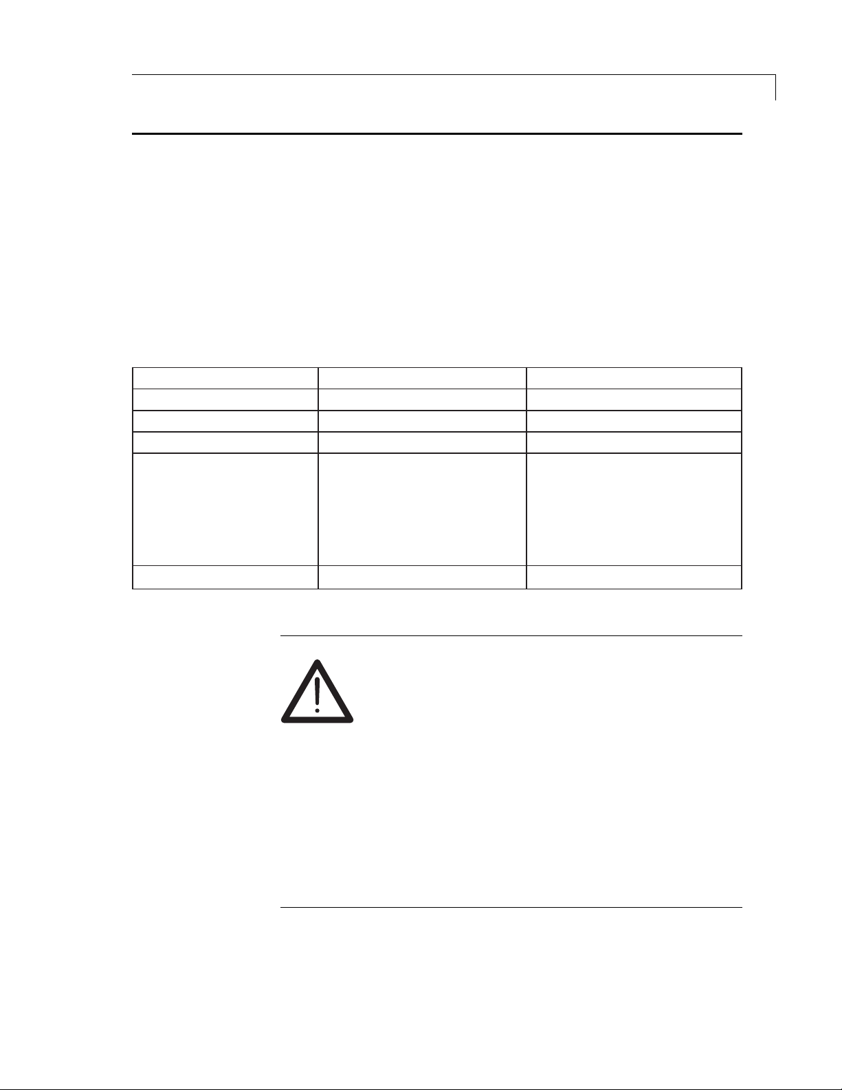
The Valco Helium Purifier (HP2) and Nitrogen Purifier (NP2) provide “pointof-use” carrier gas purification to sub-ppm levels of gaseous impurities.
Designed originally for the Valco Trace Gas Analysis system with its Helium
Ionization Detectors, the Helium Purifier provides point-of-use ultrahighpurity helium for use in any chromatographic application requiring highquality helium or other noble gas (Ar, Ne, Kr, Xe). The Nitrogen Purifier was
developed for use with our Electron Capture Detector.
Gases purified
Max. operating pressure
Max. operating temperature
Max. flow rate
Impurities removed
Impurities not removed
Helium Purifier
(HP2)
He, Ne, Ar, Kr, Xe, Rn
1000 psig
400°C
1 liter/min
Outlet impurities less than 10 ppb
O, H2, O2, N2, NO, NH3, CO, and
H
2
, based on 10 ppm total inlet
CO
2
impurities. Other impurities
removed include CF
and hydrocarbons such as CH
He, Ne, Ar, Kr, Xe, and Rn
, CCl4, SiH4,
4
4
Outlet impurities less than 10 ppb
H
based on 10 ppm total inlet impurities.
Other impurities removed include
CF
He, Ne, Ar, Kr, Xe, Rn, CH
Nitrogen Purifier
(NP2)
He, Ne, Ar, Kr, Xe, Rn, N
1000 psig
400°C
1 liter/min
O, H2, O2, NO, NH3, CO, and CO2,
2
, CCl4, SiH4, and hydrocarbons
4
WARNING!
This product is
not for use with oxygen
oxygen or gases with a significant proportion of
oxygen. The purifier’s gettering alloy is
at operating temperature
. Use with significant
amounts of oxygen can result in combustion of the
material, potential damage to the surrounding area,
and possible injury.
2
, and N
4
– either pure
pyrophoric
2
In no event shall Valco Instruments Co. Inc. be liable
for any direct, indirect, special, incidental, or consequential damage, whether based on contract, tort,
or any other legal theory and whether advised of the
possibility of such damages.
Page 3
Introduction
2
Theory of Operation
The purification substrate in the Valco purifiers is a non-evaporable
gettering alloy, with a nominal composition of zirconium, vanadium, and
iron. This alloy must be heated so that the oxide layers on the particle
surface are eliminated. This process must be performed under a vacuum or
in at atmosphere of helium (for the HP2) or nitrogen (for the NP2).
Although the gettering alloy will purify even at ambient temperatures, raising
the temperature vastly improves the life span and efficiency of the alloy.
However, the elevated temperature causes hydrogen generation, which is
trapped only at temperatures below 250°C. Therefore the Valco purifiers
have been designed to operate at a fixed temperature gradient which yields
a long life span and high efficiency and insures that any hydrogen generated will be trapped.
Accurate temperatures at the inlet (380-400°C) and at the outlet (170190°C) are maintained with the use of a precision 24 VDC power supply.
Power Supply Requirements
As stated on the purifier, the power supply must conf orm to EN 61010-1:
Section F.2.1 Limited circuit. This section mandates that the po w er source
must be limited to 42.4 VDC or less (open circuit). In addition, the energy
must be limited by one of the following means:
• the current under any condition of load, including short circuit, is not
more than 8A measured after 1 minute of operation
rated
• the source is
condition of load
• an overload protector or circuit component opens to interrupt the
power output at a lower value than 150 VA under any condition
including short circuit
The power supply is critical for safe and pr oper operation of this unit. It is therefore recommended that the
purifer be used only with the power supply received
with it.
or set to limit its power to 150 VA under any
Page 4
Installation and Operation
This procedure describes a chromatographic installation. Although that is not
the only possible application, it is the most common. It is up to the user to
determine whether the purifier is suitable for a particular application based
upon the specifications of the purifier.
Installation
The Valco HP2 and NP2 are two part systems comprised of the purifier and
the power supply. The purifier must be installed in a vertical position to
eliminate the possibility of channeling. For best results, do not modify the
fittings or tubing lengths; small particles which might be generated by such
modifications are difficult to remove and can restrict the flow.
1. Connect the input line (tagged INLET) to a carrier gas cylinder with a
high purity regulator. (Save the caps to seal the purifier whenever you
remove it from the system.)
2. Purge the system for 15 to 30 minutes at 20 to 30 mL/min to eliminate
air from the getter material.
3
3. Connect the barrel connector of the power supply to the purifier .
4. Connect the power supply to mains (115/230 VAC). The LED on the
5. Connect the purifier output line to the chromatographic system’s carrier
Activation
When the purifier reaches operating temperature (usually in about 2½
hours) the getter will be activated. Once the getter is activated, active
gaseous impurities such as H
are captured and chemisorbed on the getter surface. Only noble gas atoms
are not affected. Once adsorbed, oxygen, carbon, and nitrogen atoms
cannot be released by the getter material even at its melting point (1400°C),
due to the formation of strong chemical bonds with the alloy atoms.
Hydrogen atoms behave quite diff erently , diffusing into the getter material
bulk more quickly than the other atoms and becoming almost uniformly
distributed within the bulk. Ho w e v er, hydrogen sorption occurs below 250°C,
achiev ed through the temperature gr adient of the trap assembl y.
CAUTION: The getter material should never be heated
when air is present.
power supply should come on to confirm power output.
gas input line using a 1/16" union (Valco Product Number ZU1).
, O2, H2O, CO, and CO2 (plus N2 for the HP2)
2
Page 5

Installation and Operation
4
Operation
Removing the HP2 or NP2 from the System
In normal operation the outside temperature of the purifier is warm, but
should not be uncomfortable to the touch. The 24 VDC po wer supply maintains the purifier trap at a constant temperature, and should be located so
that the illuminated LED can serve as a visual indicator of purifier operation.
To remove the purifier from the carrier gas line:
1. Disconnect the power supply. Disconnect the output line from the
instrument while maintaining carrier flow.
2. Allow se v er al hours f or the the getter o ven to cool. After the o ven
reaches ambient temperature, cap the output line and allow the
purifier to be pressurized for several minutes.
3. Remov e the input line and immediately cap it. This maintains a carrier
gas atmosphere on the gettering substrate, increasing its lifetime.
To reinstall, follow the instructions in the Installation section at the top of
page 3.
Page 6

Routine Maintenance
In normal usage there is no maintenance required on the purifier or power
supply. If the purifier shows signs of saturation it will need replacement.
Replacement cartridges can be ordered from Valco using the product
numbers below .
Replacing the Getter Cartridge
1. Disconnect the power supply from the purifier , but lea v e the helium
flow on.
2. Allow at least two hours for the purifier to cool.
3. Using a thin-edged screwdriver or knif e, remo v e the two hole plugs
from the side of the unit and one from the top.
Do not open or modify the trap assembly .
For an HP2:
For an NP2:
I-23572HP2
I-23572NP2
5
4. The side holes allow access to the two screws which secure the trap.
With a 5/32" allen wrench, turn each screw counterclockwise one to
two rotations.
5. If the trap is still too hot to the touch, allow more cooling time. If it can
be handled, pull it out through the hole in the top of the unit.
6. Disconnect the output line at the fitting, and cap it to allow the trap to
pressurize.
7. Hav e a second cap at the ready. Disconnect the input line at the
fitting, and cap it immediately .
8. Insert the new trap, making sure the insulation and f eed-through hole
plug are snug against the top of the trap. Push the trap assembly
down until the feed-through hole plug is resting on the top of the unit.
9. Tighten both allen screws, making sure the trap does not mov e .
10. Snap in the feed-through hole plug, and both the side hole plugs .
11. Ref er to the Installation section at the top of page 3 to get the
system back in operation.
Disposing of Spent Getter Cartridges
Obtain a return authorization number from VICI by emailing tga@vici.com or
calling 800-367-8424. The packaged getter cartridge should be clearly
marked “Traps for Disposal”.
Page 7

6
Technical Drawings
Enclosure Assembly................................................ Drawing 23575 Page 7
Secondary Assembly .............................................. Drawing 23579 Page 8
Final Assembly HP2/NP2 ........................................ Drawing 23580 Page 9
Page 8

Technical Drawings
7
REVISIONS
NEW DWG. GETTER REDESIGN (HP2) ECN #4015 17DEC97 S.WERNERA
LTR DESCRIPTION DATE INITIATED
B ECN# 4908 CHANGE ITEM 7 TO 1" WIDE (1.5") 24SEP99 JDURR
1
1
1
1
4
QTY
VALCO #
HWSC-PL4-4
I-23541-02
I-23541-01
I-23577
I-23578
PARTS LIST
DESCRIPTION
SCREW, PHMS: 4-40 X 1/4 LG
INSULATION, FRONT: HP2*NP2
INSULATION, REAR: HP2*NP2
ENCLOSURE: COVER, HP2/NP2
ENCLOSURE: OVEN, HP2/NP2
321
4A
ITEM
4B
2
.041
2
1
1
1.00'
CI608104
I-E-FELT
HWSC-SC10-48
TAPE: HIGH TEMP 1" WIDE, 100' ROLL
SCREW, SHCS: 10-32 X 3" LG, SS
U-FELT SERIES MICROFIBER 3/4" TH
6
7
8
2
1
2
HWSP-1169
I-23574-01
I-23574-02
HEATER BLOCK-A: HP2*NP2 COMPLETE
HEATER BLOCK-B: HP2*NP2 COMPLETE
SPACER: #10*1 1/8, 5/16 OD, SS
10
9
1
4
HWNUT-HEX#10-5
I-21208-48
HWSO-1751
HWJAX-10
HEATER: CARTRIDGE 42W, 24V 6" X 3/8
NUT, HEX: 10-32 X 5/16 SS
STANDOFF: 10-32*1/2, 5/16 OD, SS
JACK: POWER, PANEL SLOT MT, .1 ID PIN
14
15
121311
*
4A
1.5" X 4.0"
*
14
15
8
ASSEMBLED PROFILE
9
10
11
12
13
4B
6
7
11
10
ENSURE CLOSE PARALLEL FIT OF AND
SO THERE ARE ABOUT 2 THREADS SHOWING ~ .050
LOCK THREADED SPACERS TOGETHER WITH PLIERS
WHEN ADJUSTING FOR THREAD GAP
ASSEMBLE AS SHOWN:
1
63
THIS DOCUMENT AND THE INFORMATION WHICH IT CONTAINS SHALL NOT BE USED, EXPLOITED
OR SOLD, AND SHALL NOT BE REVEALED OR DISCLOSED TO OTHERS WITHOUT THE EXPRESSED
WRITTEN PERMISSION OF VALCO. THIS DOCUMENT SHALL REMAIN THE PROPERTY OF VALCO
AND SHALL BE RETURNED UPON DEMAND.
OTHERWISE SPECIFIED
TOLERANCES UNLESS
THREAD GAP
OF
I-23575
SHEET
23575
C
SIZE DRAWING NO.
Valco Instruments Co., Inc.
HP2/NP2
SCALE
S.WERNER 17DEC97
S.WERNER
DRAWN
DESIGNED
USA PROJECTION
CHECKED
FILE NAME SUB-DIR
23575 HP2
23579
NEXT ASSY.
FRACTIONS DEC. ANGLES
ENCLOSURE: SUB-ASSY:
1
DATE
.X.1
.XX.01
.XXX.005
1/64"
APPROVED
3
Page 9

Technical Drawings
8
REVISIONS
ECN# 4015 NEW DWG. 17DEC97 S.WERNERA
LTR DESCRIPTION DATE INITIATED
5JUN00 JDURR
ECN# 5161 ADD SERIAL TAG INFO
B
5
1
4
VALCO # QTY.
I-23575
I-23542 1
HWSC-PL6-6 4
HW-1658
HW-7603 2
I-TAG73T1-795 1
I-23572HP2 1
DESCRIPTION
TAG: 1*2" METALIZED
TRAP TUBE ASSY: COMPLETE, HP2
FEET: RUBBER, STICK-ON
HOLE PLUG: 1/2"
SCREW,PHMS: 6-32 X 3/8 LG
BASE: GAS PURIFIER HP2/NP2
ENCLOSURE: ASSY. HP2/NP2
7
5
6
234
1
ITEM
*
1
OF
I-23579
SHEET
2
4
SIZE DRAWING NO.
23579
C
Valco Instruments Co., Inc.
SECONDARY HP2/NP2
SCALE
S.WERNER 17DEC97
S.WERNER
DRAWN
DESIGNED
CHECKED
NEXT ASSY.
USA PROJECTION
FILE NAME SUB-DIR
23579 HP2
I-23580
ENCLOSURE: ASSY.
7
1
63
DATE
.X.1
.XX.01
.XXX.005
1/64"
THIS DOCUMENT AND THE INFORMATION WHICH IT CONTAINS SHALL NOT BE USED, EXPLOITED
OR SOLD, AND SHALL NOT BE REVEALED OR DISCLOSED TO OTHERS WITHOUT THE EXPRESSED
WRITTEN PERMISSION OF VALCO. THIS DOCUMENT SHALL REMAIN THE PROPERTY OF VALCO
AND SHALL BE RETURNED UPON DEMAND.
APPROVED
FRACTIONS DEC. ANGLES
OTHERWISE SPECIFIED
TOLERANCES UNLESS
3
6
*
NITROGEN MODELS USE I-23572-02
Page 10

MNL-HP2
1991 REV.7/98
C
Printed in USA
Technical Drawings
9
HP2
23580NONE
C
SIZE DRAWING NO.
OF
SHEET
REVISIONS
ECN #4015 NEW DWG.GETTER REDESIGN (HP2)
ECN #5161 SHOW SERIAL TAG
LTR DESCRIPTION DATE INITIATED
A 17DEC97 S.WERNER
B 5JUN00 JDURR
INLET
GETTERING
MATERIAL
HELIUM
NITROGEN PURIFIER
INSTRUCTION MANUAL
HELIUM PURIFIER and
Valco Instruments Co. Inc.
vici@vici.com
Web site www.vici.com
Fax Int + 41 41 925 6201
Phone Int + 41 41 925 6200
P.O. Box 55603, Houston Tx. 77255
Valco International Schenkon, Switzerland
General email: valco@vici.com Tech support email: tech@vici.com
(713) 688-9345 Sales toll-free (800) 367-8424 Fax (713) 688-9348
Valco Instruments Co., Inc.
1
63
.X.1
1/64"
THIS DOCUMENT AND THE INFORMATION WHICH IT CONTAINS SHALL NOT BE USED, EXPLOITED
OR SOLD, AND SHALL NOT BE REVEALED OR DISCLOSED TO OTHERS WITHOUT THE EXPRESSED
WRITTEN PERMISSION OF VALCO. THIS DOCUMENT SHALL REMAIN THE PROPERTY OF VALCO
AND SHALL BE RETURNED UPON DEMAND.
FRACTIONS DEC. ANGLES
OTHERWISE SPECIFIED
TOLERANCES UNLESS
4
SERIAL NO.
HP-XXXXX
MADE IN U.S.A BY
VALCO INSTRUMENTS CO INC.
MODEL NO.
HP2
.XX.01
FINAL ASSY.:
.XXX.005
DATE
APPROVED
HP2/NP2
SCALE
S.WERNER 17DEC97
S.WERNER
DRAWN
DESIGNED
USA PROJECTION
CHECKED
FILE NAME SUB-DIR
23580 HP2
FINAL ASSY
2
1
111
I-23579
I-W-17600
PARTS LIST
DESCRIPTIONITEM VALCO # QTY
1
3
POWER SUPPLY , 24VDC PS24VDC-CE
OVEN ASSY, GETTER
MANUAL, HP2 I-MNL-HP2
LINE CORD, IEC 320 TYPE
4
123
FOR 220 VAC MODELS USE I-17850
*
*
Page 11

10
Warranty
This Limited Warranty gives the Buyer specific legal rights, and a Buyer
may also have other rights that vary from state to state. For a period of 365
calendar days from the date of shipment, Valco Instruments Company, Inc.
(hereinafter Seller) warrants the goods to be free from defect in material
and workmanship to the original purchaser. During the warranty period,
Seller agrees to repair or replace defective and/or nonconforming goods or
parts without charge for material or labor, or, at the Seller’s option, demand
return of the goods and tender repayment of the price. Buyer’s exclusive
remedy is repair or replacement of defective and nonconforming goods, or,
at Seller’s option, the repayment of the price.
Seller excludes and disclaims any liability for lost profits, personal
injury, interruption of service, or for consequential incidental or
special damages arising out of, resuiting from, or relating in any
manner to these goods
This Limited Warranty does not cover defects, damage, or nonconformity
resulting from abuse, misuse, neglect, lack of reasonable care, modification,
or the attachment of improper devices to the goods. This Limited Warranty
does not cover expendable items. This warranty is VOID when repairs are
performed by a nonauthorized service center or representative. For information about authorized service centers or representatives, write Customer
Repairs, Valco Instruments Company, Inc, P.O. Box 55603, Houston, Texas
77255, or phone (713) 688-9345. At Seller’s option, repairs or replacements will be made on site or at the factory. If repairs or replacements are
to be made at the factory, Buyer shall return the goods prepaid and bear all
the risks of loss until delivered to the factory. If Seller returns the goods,
they will be delivered prepaid and Seller will bear all risks of loss until
delivery to Buyer. Buyer and Seller agree that this Limited Warranty shall
be governed by and construed in accordance with the laws of the State of
Texas.
The warranties contained in this agreement are in lieu of all
other warranties expressed or implied, including the warranties
of merchantability and fitness for a particular purpose.
This Limited Warranty supercedes all prior proposals or representations oral
or written and constitutes the entire understanding regarding the warranties
made by Seller to Buyer. This Limited Warranty may not be expanded or
modified except in writing signed by the parties hereto.
 Loading...