

Page 1

Valco Instruments Co. Inc.
Instrumentation
Temperature Controller
Instruction Manual
P. O. Box 55603, Houston, TX 77255
(713) 688-9345
•
Sales toll-free (800) 367-8424
Fax (713) 688-8106
MAN-ITC
Rev. 8/96
Printed in USA
Page 2

Table of Co ntents
1. GENERAL DE SCRIP TION. ...... .... .... ...... .... .... .... ...... .... .... ...... .... .... ...... .... .... ...1
1.1 Standard Features
1.11 Thermocouple Sensor
1.12 Proportional Heater Power Control
1.13 Power Attenuation
1.14 Zero Crossover Power Application
1.15 Digital Temperature Setting
1.16 Compact Rugged Construction and Functional Layout
1.2 Specific ations and Model Codes
1.3 Technical Description
1.31 Thermal System Overview
1.32 ITC Block Diagram by Function
1.321 Input Amplifier
1.322 Thumbwheel Switches and D/A Converter
1.323 Differential Comparator
1.324 Heater Power Switch
1.325 Thermocouple Break Detection
1.326 Proportional Power Control
1.327 Power Attenuation
1.33 Proportional Power Control
1.34 Power Attenuation
Pag e
2. OPERATION . .... .... .... .... .... .... .... .... .... .... .... .... .... .... .... .... .... .... .... .... .... .... .... .... .10
2.1 PHYSICAL LAYOUT OF THE ITC
2.2 Thermocouples
2.3 Setpoint (Set °C)
2.4 Propor tioning Bandwidth
2.41 Bandwidth Defined
2.5 Install ation
2.6 Troubleshooting and Schematic Di agram
2.61 Situation:
PWR ON indicator fails to illuminate; instrument does nothing.
2.62 Situation:
TCPL indicator ON continuously; no power applied to heater
2.63 Situation: No power being applied to heat er ; TCPL indicator OFF.
3. WARRANTY ............... .......... ........ ........ .......... ........ ........ .......... ........ ........ .....19
4. TECHNICAL DRAWINGS .................... .............. ................ .............. .............20
Page 3

1. INTRODUCTION AND GENERAL DESCR IPTION
The Instrumentation Temperature Controller (ITC) is an isothermal temperature
controller intended for broad spectrum usage in thermal systems common to
modern analytical instrumentation. The instrument is designed to be a flexible
building block with which the user can config ure a ther mal system to suit p art icular
requi rements. Althoug h the contr oller is only a si ngle elemen t in such a sys tem,
its flexibility and performance ultimately determine the stability, reproducibility, and
accuracy of the enti re syst em.
Inasmu ch as we do no t attempt to prese nt a por tfolio o f specif ic appli cations, t his
manual is m ore gener al th an sp ecif ic. Inst ead, we ar e att empti ng t o str ike a spar k
of in tuitive understa nding a nd intere st for how the ITC functio ns. Th e ITC’s function an d relat ionsh ip to therm al syst ems ar e the mos t valuable n otion s transm itte d
by this manual. Just as there i s no appl icati on manua l for vice- grip pliers, there i s
not an application manual for the ITC. Both are basic, extremely useful devices,
whose rea l worth is det ermined by th e use r.
1.1 Standard Feat ures
1.11 Thermo couple Sen sors
The ITC utilizes thermocouple sensors fabricated from ordinary thermocouple wire.
A variety of factor s lea d to th is b eing th e bes t choi ce of senso rs:
•
Sensor junctions of very low mass can be easily fabricated. Lower mass
means quicker recognition of temperature changes.
•
Thermocouples are inherently rugged, requiring little in the way of special
handling precautions.
•
Thermocouple wire is inexpensive and readily available.
In keeping with this choice of sensors, the instrument is appropriately equipped
with:
•
Automatic reference junction compensation.
references to 0°C, regardless of ambient temperature.
•
Thermocouple break detection.
power circuitry will be disabled, and a front panel indicator illuminat ed.
•
High impedance differential input circuitry.
instrument to tolerate floating or grounded thermocouples, with high
common-mode noise immunity.
The ea se o f fabr ic atio n for sens ors compa tible wit h th e IT C is suc h th at us ers can
seriously consider making their own. (In many cases, all that is needed is a small
torch, silver solder, and a roll of thermocouple wire.)
Should the ther mocouple break, the heater
Circuitry automatically
This circuitry allows the
1
Page 4

1.12 Proportional Heater Power Control
The ITC utiliz es propor ti onal power applic ation t o minimiz e temper ature overs hoot,
and improve temperature stability about the setpoint. Controls are accessible to
the user, allowing the proportioning bandwidth (in
o
C) to be adjusted to meet
specific requirements.
1.13 Power Attenuation
Many te mperatu re co ntroll ers a re used in con junct ion wit h vari acs (var iable o utput
transformers) in order to improve temperature stability. By reducing the maximum
power available to the heater, the user is adjusting the heater "size" to suit his
particular thermal system. This is a practical, flexible solution to the problem, but
requi res two devi ces to con trol the t emperatu re, one of whi ch is heavy, ineffi cient,
and expensive.
The ITC employs a pushbutton switch so the user can attenuate the total power
available to the heater circuit. Attenuation is selectable from 0 to 90%, in increments of 1 0% .
1.14 Zero Crossing Power Application
Power is applied to the load in increments of integral half cycles, only. This
technique drastically reduces RFI/EMI normally associated with high current AC
switching.
1.15 Digital Temp erature Setting
The ITC employs a bank of three digital thumbwheel switches for temperature
setpoint selection. The setpoint is selecta ble in 1
o
increments. The most obvious
advanta ge t o thi s s che m e is 10 0% se tt i ng r epe at abi l ity.
1.16 Compact Rugged Cons tructio n and Func tional Layout
The ITC’s physical characteristics are strictly utilitarian. In all cases, rugged
construction techniques are employed, insuring that the assembled instrument is
not delivered by a freight company in kit form. The instrument is housed in an
aluminum/cycolac enclosure measuring 2.4" x 8.3" x 5.9". The top of the enclosure c an b e qu ickl y r em oved, a l low ing ac ces s to al l f u ses, e lec tr on ic s, etc.
It is worthy of note that almost all electronic components are mounted on a single
printed circuit board. This feature directly translates to simple troubleshooting
methods and minimal spare parts inventory.
2
Page 5

1.2 Product Numb ers and Spe cifications
Produc t Nu mbe rs: ITC 10 X
X corresponding to
399 for 0°C to 399°C range
999 for 0°C to 999°C range
Example:
ITC103 99: ITC, 1000 watts m aximum he ate r power, 0°C to 399°C range
Sensor Requirem ent Thermocouple; Ty pe K
Range 0° to 390°C, or 0° to 999°C, as ordered
Absolute Accurac y
±
.5% of full scale
Repeatability .5°C at constant ambient
Sensit i ti vi ty to Am bi en t Ch an ge s . 05° C per ° C c ha nge
Operati n g A mbi en t 10° t o 5 0°C
Switched AC Power 1000 watts;
zero-crossing erro r: 5V AC max.
Proportioni ng Ba ndwi dt h
±
3
°C
Proportioni ng Freque nc y 2 Hz
Setpoint 1° C increments; push button selection
Max. Power Input Requirement 10.0 amps at 117 VAC
Power Attenu ati o n 0 to 90 % in 10% i ncr eme nt s
Physical Dimensions 2.4" x 8.3" x 5.9"; weight 1 lb. 14.4 oz.
Visual I ndi c at or s
•
Power On (PWR) - illuminated whenever the instrument is plugged
into a source of 120V AC, and the PWR switch is in the ON position
•
Heater On (HTR) - illuminated whenever the controller applies
power to the heater
•
Thermocouple Fault (TCPL) - illuminates whenever thermocouple sensor
opens. (If a sensor failure is detected, heater power is automatically
interrupted, and t he HTR i ndicator will remain O FF.)
3
Page 6

1.3 Techn ical Description
A general knowledge of the ITC’s organization and operation is helpful to its
successful implementation. To facilitate understanding, three questions are posed:
1. What position does the ITC occupy in a thermal system?
2. How is the ITC organized to accomplish its task?
3. What is the most important aspect of the ITC’s organization?
These ques t io ns ar e a nswere d by Se ct ion s 1 . 31, 1.3 2, and 1 . 33, re sp ect ive ly.
1.31 Thermal System Overview
Figure 1
depicts a generalized closed-loop control system. The system is termed
closed-loop since the controller bases its corrective actions on the actual status of
the controlled function. In an open-loop system, corrective actions are based on
anticipated stat us. Closed-loop syste ms are defi nitel y pre ferable.
CONTROLLED
FUNCTION
SENSOR
CONTROLLER
CORRECTION
ELEMENT
Figure 1
The system is compr ised of:
•
Controlled Fu nction .
•
Sensor.
•
Controller.
Appropriate to the function; level sensor, pressure transducer, etc.
Determines when corrective action is necessary, based on
Water level, air pressure, etc.
information supplied by the sens or.
•
Correction Element.
Means of adding water, increasing pressure, etc.
With slight modification, the diagram becomes appropriate to a thermal system
utili zing an ITC, as show n in
Figure 2
.
HEATED
ZONE
THERMOCOUPLE
INSTRUMENTATION
TEMPERATURE
CONTROLLER
(ITC)
HEATER
Figure 2
4
Page 7
It is readily seen that the ITC is responsible for maintaining the temperature within
the heated zone. However, proper selection and application of the thermocouple
and heater are essential if the ITC is to perform its function. (Refer to Section
2.2.)
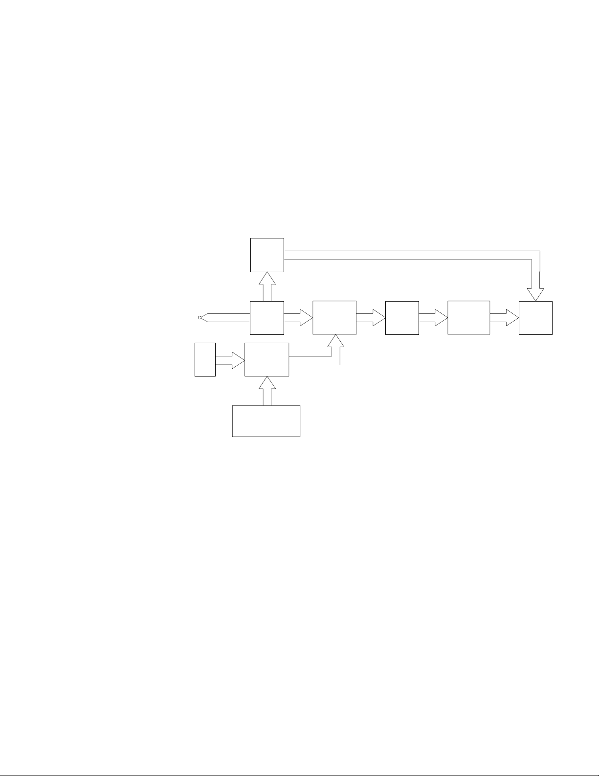
1.32 ITC Block Diagram by Function
Almost any electronic device can be described by a block diagram of its circuit
elements, each element performing something essential to the function of the
device. Indeed, such a diagram is typically the first state in its design. Further,
devices of simi lar fu nction wil l have simila r block diagrams.
TCPL
BREAK DE-
TECTION
SENSOR
SET POIN T
SELECT
INPUT
AMP
D/A
CONVERTER
DIFFER E NT I AL
COMPARATOR
ZERO
CROSSING
SWITCH
POWER
ATTE NUATOR
HEATER
POWER
SWITCH
Are these blocks supposed
to correlate to items in
PROPORTIONAL
POWER
CONTROL
1.321 and following? Nomenclature needs to be
consistent. RC
Figure 3
The function of the ITC is to control the temperature in a heated zone. A brief
discussion of what is required to perform the function reveals the elements
conta ine d i n i ts bl ock dia gra m,
Figure 3
.
1.321 Input Amplifier
The signal supplied by the thermocouple is too small to be recognized by the other
circ uit el ement s (appr ox. 50 microvolts /
o
C). Therefore, t he si gn al m ust b e amp l ifi e d
to a us ef ul level .
1.322 Set Point Selectors and D/A Convert er
The th umbwheel sw itches provi de a means of repre senting th e desired t emperature within the heated zone. (This temperature is hereafter referred to as the
setpoint
.) The switches prov ide a digit al repres entation o f the setpoi nt, which i s
then c onverted to a more useful s ignal by mea ns of a te n-bit D/A convert er. The
D/A converter conforms to the same transfer function as the input amplifier; i.e., a
representation of 100° C by the input amplifier is identical to the D/A converter’s
repres ent a ti on of 10 0
o
C.
5
Page 8

1.323 Differential Comparator
A dif ferential comparat or is u sed to co mpare the output o f the D/ A converte r with
that of the inp ut ampl ifier. Subsequent ly, the com parator ’s output den otes whe ther
the zo ne t emp era t ur e is hi gh er or l ower tha n the se t poin t .
1.324 Heater Power Switch
In accordance with the comparator’s decision, the power circuitry will apply power
to the hea ter wh en t he zone temper atur e is below t he s etpoi nt a nd int err upt power
when i t i s ab ove th e s etp oi nt .
In strictly theoretical terms, the above four elements are all that would be required
to imp leme nt th e contr olle r’s fun ction . However, prac tical appl ica tion r equi res three
additional elements:
1.325 Thermocouple Break Detection
The most common physical malfunction in thermocouples is a break, or open
circuit. If a break occurs, the input amplifier can no longer report the zone
temperature, and usually will report the ITC’s temperature, instead. From the
preced ing d isc ussi on, one can de duce t hat t his i s a pot enti all y disa stro us s ituat ion.
However, a separate circuit is employed specifically to detect a break condition. Its
output will cause the Heater Power Switch to be disabled, and a front panel
indicator to be illuminated whenever a break occurs.
1.326 Propor tional Power Control
To this point, power application to the heater has been described as simply
"appl ied or inte rrupted ". In rea lity, this would be anal ogous to tr ying to m aintain a
dragster’s speed at 30 mph using full throttle applications only. Obviously, power
must be delivered according to the need. For this reason, the ITC employ s proportional power control, where net power is delivered to the heater according to
the difference between the setpoint and zone temperature. The proportioning
technique is discu ssed in Se ction 1.33 .
1.327 Power Attenuation
Effective heater size can be tailored to the application by proper adjustment of the
power a ttenu atio n con tro l. Exce ssive h eat er rat ings ar e oft en t he ca use o f sys tem
instability at near ambient temperatures. Proportional control and power
attenuation work hand-in-hand to produce excellent temperature stability. (Refer to
Section 2.3.)
1.328 Zero Crossing Switch
This allows the he ater to come on only if t he AC wavefor m is at zero to supp ress
noise on th e p ower li ne.
1.33 Propor tional Power Control
Alth ough t he IT C’s inpu t amp lifi er a nd D/A ci rcui tr y are acc urate and predi cta ble in
their temperature representations, they do not in themselves constitute a good
temperature controller. In a control system, the essential factor is stability. A
temperature controller is not doing its job if the zone temperature is allowed to
oscil late about the setpoint to a degree which upsets the process. In shor t, the
aim is to reduce a thermal system’s natural tendency to oscillate to a level where it
is not significant.
6
Page 9

If zone heat er p ower i s sim ply appli ed o r int err upted acc ordi ng to t he c ompara tor’s
verdict (correction required/not required) the result is wholly unacceptable. To
illustrate:
Assume that a zone is to be heated from room ambient to 75
power is applied until the temperature r eaches 75
o
, and then interrupted, the
temperature will overshoot. As the temperature settles back to 75
o
C. If 100%
o
, 100%
power will again be appli ed in an effor t to prevent the temperature from falling
below the setpoint. As a result, the temperature will overshoot again. In this
manner, the temperature will continue to oscillate about the setpoint.
As can be seen, on/off, stop/go, etc. are corrective measures that would make the
ITC unacceptable for all but the crudest applications.
The key to obtaining acceptable stability lies in applying heater power relative to
the need. Using the above example, but employing proportional control, more
reason abl e r esu l ts ar e ob t aine d:
o
While the temperature rises from ambient toward 75
continuously, just as before. However, at a poi nt just
o
, the power is reduced to 95%. As the temperature continues to rise,
70
C, power is applied
the setpoint, say
below
power is linearly reduced such that power will be applied 50% of the time
when the temperature reaches the setpoint, and only 5% when it reaches
o
. When the temperature begins to settle, the process is reversed. Heater
80
power is gradually increased as the temperature declines toward the setpoint.
As a result, the temperature will tend to stabilize at a point where the power
application is sufficient to maintai n equilibrium.
In conclusi on, the syste m’s tendency to oscil late is greatl y reduced i f some form of
proportional control is employed.
Commonly, two methods can be used to electronically control AC power: phase
proportioning, and time proportioning. With phase proportioning, some percentage
of eac h AC cyc le is appl ied to the l oad. While this method is ju st fine for power
drills, it is not acceptable for instrument use. This is due to the fact that the power
is not switched at zero-crossings. Therefore, large amounts of RFI/EMI can be
generated. (If such elec trical "no ise" is generated, it may upset the operation of
other instruments in the vicinity.) With time proportioning, the average power is
contr oll ed by divi din g time int o sp ecif ied p eri ods. Duri ng ea ch pe rio d, t he pe rcent age of power ON versus OFF time is proportional to the difference between the
setpoint and the controlled temperature. Power is switched only at AC voltage
zero-c ros s ing s, avoidi ng RFI /E M I ge ne rati o n.
Figure 4
is a graphic represent ation of time pr oport ioning as it is implemen ted in
the IT C. T he hear t of the p rocess is the propo rti oning waveform. Thi s sawtoothshaped waveform defines three important parameters of operation: lower temperature boundary, setpoint, and upper temperature boundary. The setpoint will always
be situated in the exact center of the waveform. The
represents the point below which 100% power will be applied. The
ary
temperature boundary
plie d. And, as sta ted ear li er, the
represents the point above which no power will be ap-
setpoint
denotes the point at which power will be
lower temperature bound-
upper
applied 50% of the time. Observe, also, that between the two boundary temperatures, the average applied power is linearly proportional to the difference between
the s etp oi nt an d th e actu al t em per atu re wi th in th e h eat ed zon e.
7
Page 10

1
PROPORTIONING
WAVEFORM
POWER
APPLICATIONS
CONTROLLED TEMPERATURE RISING FROM AMBIENT;
1
NOTICE POWER APPLICATION IS PROGRESSIVELY REDUCED AS T HE TEMPERATURE
RISES
OVERSHOOT; NO POWER APPLIED
2
EQUILIBRIUM;CONTROLLED TEMPERATURE HAS SETTLED AT APPROX. 40% POWER
3
TIME
2
3
102°
98°
Figure 4
The number of degrees between the upper and lower temperature boundaries is
referred to as th e
proportioning bandwidth
. Proper adjustment of the bandwidth
will further enhance temperature stability within the heated zone. Some guidelines
for adjust ment ar e found in S ectio n 2.4 .
1.34 Power Attenuation
In the precedi ng sect ion, pr opor tion al power co ntrol was desc ribed as the pro cess
by which the ITC applies a percentage of power proportional to the difference
between the setpoint and the controlled temperature. It is not unusual that this
technique, alone, will not yield acceptable temperature stability. Commonly, this
situation occurs when near ambient temperatures are desired of a thermal system
orig inally de signed for h igher temp eratures. Cons equently, t he heater s ize (rated
output) is much too large for system demand.
In compensating for such difficulties, laboratory personnel often employ variacs
(variable output, s tep-down transformers) to attenuate the power delivered to the
heater.
Power delivere d to the heate r can be atte nuated in incr ements of 10% by setting
the ITC’s front panel mounted ATTN pushbutton switch. This control performs
exactly the same function as the variac mentioned above. However, the method
by which the ITC performs this function differs considerably from variac operation.
Here’s how :
A variac provides a means of adjusting the voltage (and consequently, the
power) applied to the heater. The ITC varies the number of half-cycles
to be delivered by its power circuitry. For example, 100% is available
able
avail -
when the ATTN control is set to 0. I f the attenuation is changed to 4 (40%),
only six of every ten half-cycles are available for delivery to the heater. As a
result, the heater output will be 60% of its full rating.
8
Page 11

In summary, the proportioning circuitry determines the percentage of time during
which power will be applied, while the attenuati on circuitry deter mines what percenta ge o f power is t o be avai l able fo r d el ivery during t his t ime.
9
Page 12

2.
In thi s sec t ion pr ac ti cal c on si der ati on s for th e IT C ’s usage a re di scu sse d.
OPERATION
2.1 Physical layout of the ITC
Following are illustrations of the var ious models of the Instrumentation Temperature
Controller.
the ITC.
models. The numbers on the illustrations relate to the numbered parts below.
Figure 5
Figures 7
shows the front panel, and
and 8 show the back panels of the 110V AC and 220V AC
1
2
34
Figure 6
56
shows the top v iew of
A
T
T
5999
OPEN
TCPL
PWR
1
Power Switch PWR
Front mounted toggle switch controlling power to heater and power supply
circuits.
2
Power On Indi cat or
Front mounted neon indicator; illuminated whenever the power switch is in
the ON position and power supply fuse is intact.
3
Heater Power On
Front mounted neon indicator; illuminated whenever instrument applies
power to heater; will not illuminate if heater is not connected, or if broken
thermocouple is detected.
4
Thermocou ple Fault In dicator
Front mounted LED indicator; lights whenever thermocouple circuit is
broken.
ON
Figure 5:
HTR
Front panel, model ITC10
N
S
E
T
C
°
5
Heater Power Attenuation Switch
Front panel mounted bidirectional ATTN switch; denotes heater power
attenuation in increments of 10 percent.
6
Setpoint Swi t ches
Front panel mounted switches; denote controlled temperature setpoint in
7
Calibr ation Adj ustment s
Printed circuit board mounted pots; DO NOT attempt adjustment.
10
o
C.
Page 13

10
8
9
7
7
Top view, model ITC10
8
Thermocouple Connector
Figure 6:
Printed circuit board mounted connector; connect red lead of ther mocouple
to Terminal R.
9
.5 Amp Fuse
Printed circuit board mounted; fuses power supply primary circuitr y.
10
10 Amp Fuse
Printed circuit board mounted; fuses heater power circuitry.
13 11
13
THERMOCOUPLE
Y R
Figure 7:
HEATER
POWER
Back panel, model ITC10 110V AC
120V AC
10A MAX
13 12 13
THERMOCOUPLE
Y R
Figure 8:
HEATER
POWER
Back panel, model ITC10 220V AC
220V AC
10A MAX
11
Page 14

11
Heater Receptacle, 120V AC only
Rear panel mounted AC receptacle; two-wire plus ground; connects heater
via standard 16 or 18 gauge three-wire power cord (not supplied).
12
Heater Receptacle, 220V AC only
Rear panel mounted AC receptacle; two-wire plus ground; connects heater
via power cord (black and white to heater, green to ground). Power cord is
not supplied.
13
Top Cover Reta ining Scr ews
Remove these screws to gain access to inter ior of ITC.
2.2 Thermoco uples
Thermocouples, when used properly, are a very expedient and reliable means of
sensin g t empera ture. In t his sect ion, we wi ll a ttemp t to h elp the use r avoid cer tai n
genera l and s pe ci f ic pit fal ls in t her m oc oup le u sag e wi t h t he IT C.
Ther mocoup le meas uri ng junc tions are fabr icate d by jo ining two di ssimi lar met als.
A type K thermocouple is formed from chromel and alumel. In theory, the thermocoupl e is func tio nal so l ong as th e t wo meta ls r emai n in c ont act. (Th is do es i mply
that a measuring junction can be formed by twisting two wires together. We would
point out that the junction will not be suitable for any real application, however.)
Maintaining the integrity of the measuring junction is of prime importance. This
means th at for a given appl icatio n, thought mu st be given the junc tion’s maxim um
attainable temperature, corrosion resistance to its environment, and mechanical
strength.
Commercially available thermocouples are usually joined by welding. This
produc es a juncti on in whi ch the max imum temperat ure and cor rosion resi stance
properties are those of the metals themselves. For applications below 400
quite serviceable junction can be formed by twisting the bare ends of the wire
toget her, and then sec uring wit h silver sold er. For applicat ions above 400
o
C, a
o
C, t he
junction should be welded. In the case of silver soldered junctions, we would
again point out that the environment and maximum temperature must not be
harmful to the solder.
It is important to note that considerations pertaining to junction integrity are also
applicable to the
insulation
around each wire. As sta ted earl ier, a new junctio n is
formed each time the two thermocouple wires come into contact. Obviously,
unplanned junctions are to be avoided.
In matters concerning the thermocouple, measuring junction mass, thermal
conduc tivity of the contr olled mediu m and placem ent can grea tly affect con trolled
tempe ratur e st abil ity. In Sect ion 1 .32 6, an examp le was give n ill ust rati ng te mperature instability. It was pointed out that stability is obtained by supplying heater
power proportional to the need. At this point, it is important to recall that the
thermocouple is responsible for telling the controller what the need is. Most
importantly, any change in temperature must be reported without appreciable
delay. This causes instability, regardless of how craftily the correction is carried
out. This notion of minimizing delay is carried to fact by observing two rules:
12
Page 15

1. The meas uring junct ion sh ould be o f the l owest ma ss pra cticabl e for the a pplication. Simply put, the higher the mass, the more time required for the junction to
reach t h e t emp era t ure of i ts s ur ro undi n gs.
2. The measuring junction should be placed as close as possible (thermally) to
the heater. Whenever there is doubt about proper location of a thermocouple,
follow these suggestions:
a. Place the junction directly between the heater and the object to be heated,
as close to the heater as possible.
b. In a stirred air or liquid bath, place the junction immediately downstream
from the heater.
In addi tion to the mo re commo n cons iderati ons, t here are a few impor tant speci fic
notions regarding thermocouples to be used with the ITC.
•
Electrical contact.
If the measuring junction is in electrical contact with an
object, that object must be connected to AC ground. For example, this would
require a heater block to be grounded unless the ther mocouple is electrically
insulated from it. (The junction must float or be grounded.)
•
Thermocouple resistance.
The following data describes the thermocouples
normally shipped with the ITC:
ITC-K: 10 ft., 28 gauge, 40 ohm , ANSI Type K
2.3 Setpoint (Set °C)
Loosely defined, the setpoint denotes the desired temperature within the heated
zone. However, the user should be aware that the denoted setpoint is not necessarily the temperature at which the zone will stabilize.
To be more precis e, the setp oint denote s the tempera ture at whic h power will b e
applied 50% of the time. It is entirely possible that the zone will require more or
less t han 50% power to ma intain s tabilit y. As a cons equence, t he zone te mperature will settle above the setpoint if less than 50% power is required, and below
the s etp oi nt if mor e th an 50% powe r i s ne eded .
Essentially, this characteristic offset is brought about by the proportional power
control method used in the ITC, coupled with the thermal characteristics of the
user configured heated zone. Without prior knowledge of the zone’s heat input vs.
heat l oss proper ties, the only certainty is that the zone temperature will stabilize
somewhere
settl es, can be op timized by adjustment of the propo rtion ing bandwidt h. (Refer to
Section 2.4.)
within the proportioning bandwidth. Exactly
the temperature
where
13
Page 16

2.4 Propor tioni ng Ban dwidth
Current models of the ITC may have fi xed valued resistors in the trim
Note:
pot location for the bandwidth calibration. If the ITC needs fur ther calibration
they may be replaced with 10K trim pot and the following text will explain the
band width adjustments.
Given that the controlled temperature is reasonably accurate, stability becomes a
most important measure of system performance. Perfect stability is obtained by
applying the exact amount of power required to offset a system’s demand. In
addition, the power must be applied
Think about thi s. Theor etical n otions l ike "exact" and "ins tantaneo us" soon reveal
the me ani ng of t he term, "opti mum".
In attempting to achieve optimum stability, we assume that the user will experiment
with t h e proport ion i ng ban dw id th ad jus tme nt po t . (Refer to Sec t ion 2. 1, i tem 7 . ) In
keeping with this assumption, we offer the following explanation of bandwidth
adjustment.
2.41 Bandwidth Defined
Rigorously defined, bandwidth is the peak to peak value of the proportioning waveform, expres sed in degre es centigrade. The ba ndwidth pot con trols the heig ht of
the wavefor m. More impor tantl y, t he heigh t deter mines the slope of the diagon al.
In
Figure 9
6° bandwidth. In each case, the controlled temperature is depicted 1 below the
peak height of the waveform. Notice that the resulting power applications are
differen t. In fact, power is applied twice as l ong in the 3° example as in the 6°
example. This is due to the slope of the diagonal, and, as we shall see, is a very
usefu l t hi ng t o re memb er.
, two waveforms are shown: one with 3° bandwidth, and the other with
instantaneously whenever a d emand occ urs.
The important thing to notice in
changes within the bandwidth, the resulting change in heater power is dependent
on the slope of the diagonal. More specifically, the
power is controlled by the slope of the diagonal.
If, in each case, the temperature falls 1° (1° excursion), the resulting changes in
applied power are dramatically different. In the 3° example, ap plication ch anges
from 33- 1/3% to 66- 2/3%. The same 1 excursion in a 6° bandwidth causes
application to change from 16- 2/3% to 33- 1/3% per degree and 16- 2/3% per
degree, respectively. By observation, increasing the bandwidth decreases the
amount of ch an ge i n averag e ap pl i ed pow er for a g iven cha ng e in t em per atu re.
How does all this relate to stability improvement? Well, assuming that a stability
problem ex ist s, it may be attr ibutabl e to excessi ve heater power. By this, we mea n
that the heater is simply too powerful for the application. The situation usually
results from designing the system to heat quickly and operate over a broad
tempe rature range. The pr oblem is chara cterized by the contro lled temper ature’s
tendency to spend most of the time above the bandwidth, occasionally falling into
its upper reaches. The temperature will not stay within the bandwidth because
14
Figure 9
is that as the controlled temperature
rate of change
in applied
Page 17

POWER AP PLI CATIONS
3
°
TIME
6
°
CONTROLLED TEMP
1° EXCURSION
POWER AP PLI CATIONS
CONTROLLED TEMP
1° EXCURSION
CONTROLLED TEMP
EXCURSION TEMP
Figure 9
power is i nc rease d too ab rupt ly, quickly dr ivi ng th e temper ature up, out of re ach. If
the heater size cannot be reduced, the bandwidth must be increased. Doing so
will decrease the rate of change in applied power, hopefully increasing stability.
Always allow ten to fifteen minutes after making each adjustment before making
another. This will allow the system enough time to reveal whether or not further
adjustment is required.
As a consequence of increasing the bandwidth, the user should be aware that the
controlled temperature is usually shifted upward, as well. This notion is most easily understood by noting the position of the 1% power point before and after adjustment. Remember that the system will still require the same average power to
maint ain a given temp erat ure. There fore, as t he bandwi dth is i ncre ased, the given
power point shifts upward, carrying with it, the controlled temperature.
Note that the controlled temperature shifts upward only if it was originally trying to
stabilize above the setpoint (50% power point). There usually is no stability
problem when the temperature is settling below the setpoint. However, we will
point out that in this situation, the temperature will shift downward when bandwidth
is increased.
The valu e of th e ba ndwi dt h ( i n ° C) ca n be de termined by t h e fol low ing met h od:
1. Reduce the setpoint temperature until the HTR indicator is OFF continuously. Make note of this temperature.
2. Increase the setpoint until t he HTR indicator is ON continuously. Make note
of this temperature.
3. Determine the difference between the two temperatures. This value is the
bandwidth.
15
Page 18

2.5 Installation
The following discussion is intended to assist you in the initial installation of an
ITC. It is assumed that you have read the foregoing portions of this manual.
Check the instrument for shipping damages. Open the instrument and check for
loose components. There shouldn’t be any. In the event that damage is noted,
notif y th e carr ier imme diate ly. Valco a ssumes no r espo nsib ilit y for dam age in cur red
in shipment.
Assuming no damage is seen, perform the following checkout. You will need an
ordinary incandescent light or other resistive load that provides indication of when
power is applied.
1. Connect the load to the ITC. In 110V models, a receptacle (labeled P1) is
provided which accepts ordinary three-wire appliance plugs. The 220V uses a
cinch socket.
2. Connect t h e in st r ume nt t o a su it abl e s our ce of 12 0V AC.
3. Set the set poin t and at tenuati on switc hes to 0 . Swi tch th e instr ument o n. The
TCPL indicator should illuminate momentarily. (The instrument is determining
whether or not its thermocouple is OK.) The HTR indicator should be OFF.
4. After allowing the instrument to warm up for a few minutes, increase the
setpoint until the HTR indicator flashed with a 50/50 duty cycle. The setpoint
shoul d a ppr oxima te t he am b ien t temp era t ur e.
5. Hold the thermocouple’s measuring junction firmly in one hand. Since your
skin temperature is usually 10° above ambient (and subsequently, the setpoint),
the HT R i ndi c at or sho ul d c eas e f l as hing .
6. Increase the setpoint until the HTR indicator is ON continuously. (Try 50°.)
Change the power attenuation switch to 9. The HTR indicator should flicker faintly.
Progressively decrease the ATTN setting, noting that the HTR indicator "brightness" increases at each position. When the ATTN switch is at zero, the HTR indicator should be ON continuously, with no visible flickering.
Regarding the zone heater specifications, care should be taken to avoid exceeding
the ITC’s specifications for switched power. The ITC10 will switch loads up to
1000 watts. If you attempt to exceed this rating, the instrument will probably sacrifice its f uses and/or p ower tr iac.
The present ITC power circuitry is intended to switch resistive loads only. This
means that inductive loads, such as electric motors, solenoids, and especially
variacs cannot be switched successfully.
Damage may result if inductive loads are used.
Always use three-wire power connections for the instrument, as well as heater
connection. (Ref. Section 2.2.) It is important that the heater block, etc. be
16
Page 19

connec t ed t o AC gr ou nd . Failure t o d o so may c aus e a s ho ck haz ar d, or co ntr ol le r
malfu nctio n, or bo th.
Locate the ITC where it will not be subjected to abrupt changes in ambient
tempe ratu re. This w i ll im pr ove the c ont r ol led t emp era tur e s tab i lit y.
When installing the thermocouple, be sure to observe electrical restrictions noted
in Sect ion 2.2 .
Actual installation consists of, first, thinking about what must be done, then
connec ting the heater, and finally inserting the ther mocouple. After this is done,
turn it ON and play with the system. Notice whether or not corrections need to be
made in such areas as thermocouple location, bandwidth adjustment, etc. Enjoy!
(If you’re not enjoying yourself, cal l us. We’ll try t o help in any way we can.)
2.6 Troubleshooting and Schematic Diagram
Troubleshooting the ITC is straightforward, in most cases. The device can be
though t of as being di vided in to two sections ; ins trumenta tion an d power cir cuitr y.
Problems with the power circuitry are the most easily identified, and can be
handled with a minimum of electronics experience. Isolation and repair of malfuncti ons in th e instrum entation circuitr y require sophistic ated test equipment an d
extensi ve el ec t ron ic s expertise. For this r eas on, i t i s rec omm e nded t hat th e fa ctory
be con sul te d w he n t he foll owi ng pr oc edur es ar e of no he l p.
2.61 Situation: PWR ON indicator fails to illuminate; instrument does
nothing.
A 1/2 amp fu se i s em ployed t o fuse th e ins trum ent’s DC p ower s uppl y. If this fus e
is blown, the PWR ON indicator will not illuminate, and the instrument will not
perfor m any fun cti ons. The f use is l ocate d at the le ft re ar c or ner of t he en clos ure.
(Refer to
fact ory.
2.62 Situat ion : TCPL ind icat or ON con ti nuously; no p ower appl ied to
heater
When t he TC PL in dica tor is O N con tinuo usly, the in str ument thi nks an ope n cir cui t
has developed in the thermocouple. As a consequence, the ITC will refuse to
apply power to the heat er. The t hermo couple is co nnected t o the i nstru ment by a
barrier strip, designated B1. (Refer to
tions are snug. As a second consideration, be cer tain that proper connection to
AC ground is made in any case where the thermocouple measuring junction
contacts metal. If this is not done, the TCPL circuit can sometimes be fooled into
beli eving there is a malf unction. As a fin al considera tion, dis connect the th ermocoupl e, and check i t for elect rical c ontinui ty. If the problem is not locat ed, consul t
the fact ory.
Figure 6
, Item 10.) If the ITC persists in blowing this fuse, consult the
Figure 6
, Ite m 9.) Be cer t ai n t he se co nnec -
17
Page 20

2.63 Situation: No power being applied to heater; TCPL indicator OFF.
In this situation, the HTR indicator remains OFF. The power triac is protected
against continuous current overload with a 10 amp fuse. (Refer to
11.) If this fuse is blown, no power is available to the heater circuitry. In addition
to replacing a blown fuse, consider what may have caused the overload. The
heater and/or power triac may have developed a short circuit. This sort of occurrence i s us ual ly acc ompan ied by bu rn ed wi rin g. Be cer ta in tha t the heate r doe sn’ t
exceed the power rating for the ITC (1000 watts).
It is the case that the situation described above can occur without blowing the
fuse. If this occurs, consid er whet her or not the load i s induct ive. Rememb er that
such loads cannot be switched with the ITC’s present circuitry.
The appropriate schematic diagram is supplied in this section. Should you require
any explan at io n o f th e c ir cui try, p l ea se con tac t the fac tory.
Figure 6
, Item
18
Page 21

3.
WARRANTY
This L imited Warran ty gives the Bu yer speci fic legal rights, and a Buyer may a lso
have othe r r i gh ts t h at var y form state t o s ta t e.
For a period of 365 calendar days from the date of shipment, Valco Instruments
Company, Inc. (hereinafter Seller) warrants the goods to be free from defect in
mater ial and w orkmanshi p to the o riginal purchaser. During the warrant y period,
Seller agrees to repair of replace defective and/or nonconfor ming goods or parts
without charge for material or labor OR at seller’s option demand return of the
goods and tender repayment of the price. Buyer’s exclusive remedy is repair or
replacement of defective and nonconforming goods OR at Seller’s option repayment o f t he p r ic e.
SELLER EXCLUDES AND DISCLAIMS ANY LIABILITY FOR LOST PROFITS,
PERSONAL INJURY, INTERRUPTION OF SERVICE, OR FOR CONSEQUENTIAL INCIDENTAL OR SPECIAL DAMAGES ARISING OUT OF, RESULTING
FROM, OR RELATING I N ANY MANNER TO THESE GOODS.
The Limited Warranty dose not cover defects, damage or nonconformity resulting
from abuse, misuse, neglect, lack of reasonable care, modification or the attachment of improper devices to the goods. This Limited Warranty does not cover
expendabl e items. This warr anty is VOID w hen repai rs are perfor med by a non author ized ser vice cent er or rep resentati ve. If you have any problem loc ating an
authorized service center or representative, please call or write Customer Repairs,
(713) 688-9345, Valco Instruments Company, Inc., P.O. Box 55603, Houston, Texas
77255. At Seller’s option, repairs or replacements will be made on site or at the
factor y. If repairs or re plac ement s are t o be made at the fact or y, Buyer s hall r etur n
the goods prepaid and bear all the risks of loss until delivered to the factory. If
Seller returns the goods, they will be delivered prepaid and Seller will bear all risks
of loss until delivery to Buyer. Buyer and Seller agree that this Limited Warranty
shall be governed by and construed in accordance with the laws of the State of
Texas.
THE WARRANTIES CONTAINED IN THIS AGREEMENT ARE IN LIEU OF ALL
OTHER WARRANTIES EXPRESSED OR IMPLIED, INCLUDING THE WARRANTIES OF MERCHAN TABILITY AND FITNESS FOR A PARTICULAR PUR POSE.
This Limited Warranty supercedes all prior proposals or representations oral or
written and constitutes the entire understanding regarding the warranties made by
the Seller to Buyer. This Limited Warranty may not be expanded or modified
except i n wr it in g s ign ed by t he p arties h ere t o.
19
Page 22

4.
Assembly Drawing..... .............. .............. .............. .............. ............ ....... Drawing 21556 Page 21
Assembly Broad Drawing ............ .............. .............. .............. .............. . Drawing 22218 Page 22
Schematic – ITC Board ............. .............. .............. ............ .............. ..... Drawing 22219 Page 23
Board Conversion.... ............ .............. .............. .............. ............ ........... Drawing 21647 Page 24
TECHNICAL DRAWINGS
20
Page 23

110V VERSION
4
3
(ON BOTTOM)
1A
220V VERSION ONLY
*
3
4
9
18
4
7
8
13
*
17
(FROM BOTTOM
12
OF ENCLOSURE)
16
5
15
BLACK
GREEN
14
GREEN
WHITE
BLACK
WHITE
9
(GREEN/YELLOW 220V)
(BLUE 220V)
(BROWN 220V)
1
Valco Instruments Co., Inc.
INSTRUMENTATION TEMPERATURE CONTROLLER
PWR
ON HTR
11
LTR DESCRIPTION
A
ITC BD. ASSY. REV. M,N
B
19
2
4
YELLOW RED
34
OPEN
TCPL
6
-
A
T
T
0
N
+
10
+
++
993
---
S
E
T
C
18
20
Instrumentation
Temperature Controller
Instruction Manual
Valco Instruments Co. Inc.
18
SEE NOTE 2
NOTE: FOR 220V MODEL.
*
ITEM
1
2 PCB ASSY: ITC 10 AMP
3
4
5
6
7
*
8
9
10
11
12
13
14
15
16
17
18
19
20
21
22
23
24
25
REF
*
REMOVE ITEM 13 AND DRILL MOUNTING HOLES USING DRILL TEMPLATE A-21819.
INSTALL CINCH SOCKET #S304-AB WITH COVER PLATE ITEM 20 (A-21820).
WIRE SCHEDULE
WIRE (PCB)
TERMINAL (SOCKET)
BLACK (HOT)
WHITE (NEUT.)
GREEN (GND)
MODIFY PCB PER DRAWING A-21647
INCLUDE I-T304PCCT PLUG
ENCLOSURE C-21527 REV. G
C
ECN #2050 CLARIFY DWG
D
ECN #4668 CLARIFY 220V VERSION
ENCLOSURE: ITC, 10 AMP.
STANDOFF: 4-40*1/4, THREADED, NYLON
SCREW,PLMS: 4-40*1/4 lg,PANHD,PH,SS
STANDOFF: 4-40*1/4 SWAGE THREADED
SWITCH ASSY: ITC TEMP.CTRL. (399 DEG.C)
POWER-CORD: GREY 6' 18/3 SVT
STRAIN-RELIEF: SRR-10, HEYCO#: 5P-4 1147
LUG: FEMALE SLIP-ON, 16-14 AWG
THERMOCOUPLE-ASSY: 10'2 (ITC) K TYP
FEET: RUBBER STICK-ON
NUT, HEX: #4-40 UNC, STAINLESS
RECEPTACLE: POWER OUTLET BLACK
WIRE: 14 AWG TEFLON BLACK CSA SPEC
WIRE: 14 AWG TEFLON GREEN CSA SPEC
WIRE: 14 AWG TEFLON WHITE CSA SPEC
TUBING: HEAT SHRINK 1/4" ID.
SCREW,SMS : #4*3/8 LG, PL, SS
TAG: SERIAL, ALL ELEC. DEVICES
MANUAL: OPERATION, ITC
PLATE, ADAPTER 220V ITC PLUG
SCREW,PLMS: 6-32 X 3/8 LG
NUT, KEP: #6-32
PLUG: 4 PIN CABLE
SOCKET-MOUNT: 4 PIN PANEL
POWER CORD: "SCHUKO" PLUG
DESCRIPTION
1
2
3
REVISIONS
PARTS LIST
POWER CORD 220V
I-W-17800
BRN
HOT
BLU
NEUT
YEL/GRNGND
23
25
4
ENCLOSURE
DATE APPROVED
20FEB89
22FEB89
8AUG94
22MAR99
VALCO #
I-21527
I-22218
HWSO-4050
HWSC-PL4-4
HWSO-1650-2
I-21280-02
I-W-CS-21
HWSRR-10
HWLUG-4218B
I-21014-01
HW-1658
HWNUT-HEX#4
HW-OUTLET
I-W-14-BLACK
I-W-14-GREEN
I-W-14-WHITE
I-STUBE.250
HWSC-SM4-6
I-21988
MANUAL:ITC
I-21820
HWSC-PL6-6
HWNUT-KEP#6
I-T304PCCT
I-T304SAB
I-W-17800
J DURR
J DURR
QTY
.333
.333
.333
.125
1
1
3
9
3
1
1
1
6
1
4
1
1
4"
4"
4"
6
1
1
1
2
2
1
1
1
24
21
21
I
N
V
S
a
T
lc
R
o
In
U
M
s
tr
E
u
N
m
T
e
n
A
t
s
T
C
IO
o
N
.
, In
T
c
E
.
M
P
E
R
A
T
U
R
E
C
O
N
T
R
O
L
L
E
R
NOTE 2
ADJUST HEIGHT OF COVER
BY TURNING SCREW
1B
22
FINAL ASSY
THIS DOCUMENT AND THE INFORMATION WHICH IT CONTAINS SHALL NOT BE USED, EXPLOITED
OR SOLD, AND SHALL NOT BE REVEALED OR DISCLOSED TO OTHERS WITHOUT THE EXPRESSED
WRITTEN PERMISSION OF VALCO. THIS DOCUMENT SHALL REMAIN THE PROPERTY OF VALCO
AND SHALL BE RETURNED UPON DEMAND.
TOLERANCES UNLESS
OTHERWISE SPECIFIED
FRACTIONS DEC. ANGLES
1/64"
APPROVED
DRAWN
R.B.D. / M.C.
DESIGNED
CHECKED
FILE NAME
21556
.XX.01
.XXX.005
63
.X.1
1
ITC ASSY. 10 AMP
DATE
2/20/94
REV. M,N,P
2/20/89
SUB-DIR
\ITC\
USA PROJECTION
1
432
Valco Instruments Co., Inc.
ITC10399-220
SIZE DRAWING NO.SCALE
C
ITC10399
21556---
SHEET
OF
Page 24

22
*
*
*
ITEM
PCB
T1
F1
F2
TP1-10
CO1
CO2
C03,4
CO5,6
Z1
Z2-4
Z5
Z6
Z7
S1,5
S2-4
S6
S7
TR1
C1,2
C3,4,14
C5,6,8-10,
15,16
C7
C11
C12,13
RN1
RN2,3
Q1
Q2,3
SW1
L1,2
L3
BR1
VR1
VR2
D1
R1
R2
R3
R4
R5,7
R6
R8A
R8B
R9,R10
R11
R12
MT1-6
SC1-6
KN1-6
FC1-4
R13-14
PCB ASSY: ITC 10 AMP
TRANSFORMER 115/230V DSC4-24
FUSE: 10AMP 3AG
FUSE: 3AG SLO BLO 1/2 AMP (TYPE 313.5)
TERMINAL: HOLLOW USECO
CONN: 20 PIN HEADER, ANSLEY
CONN: 2 POSITION BLOCK
CONN: 2 PIN MOLEX
CONN: DIALIGHT
IC: K TYPE THERMOCOUPLE CONDITIONER
IC: COMPARATOR ( DUAL )
IC: DUAL TYPE D FLIP-FLOP
IC: DECIMAL CTR/DIVIDER. RCA OR MOT
IC: OPTO-TRIAC MOC3011
SOCKET: DIP, 14 PIN LOW PROFILE
SOCKET: DIP, 8 PIN, LOW PROFILE
SOCKET: DIP, 16 PIN, LOW PROFILE
SOCKET: DIP, 6 PIN, LOW PROFILE
TRIAC: T0220, 400V 15AMP
CAP: ELECT, 220uF 35V, AXIAL LEAD
CAP: TANTAL, 4.7MF 35V
CAP: CERAMIC, .022uF 50V, .250 LEADS
CAP: CERAMIC, 27 PF 50V
CAP: MONO CERAMIC, .22 uF 50V, .2"LEADS
CAP: TANTAL, 1MF 35V
RES NET: 10 K, 16 PIN DIP, DISCRETE
RES NET: 100 K, 16 PIN DIP, DISCRETE
TRANSISTOR: NPN, T093, DARLINGTON
TRANSISTOR: PNP, TO93, DARLINGTON
SWITCH: TOGGLE DPDT-RPC-N-P-S
LAMP: NEON, RED (9001-52-C-03-2RN)
LED: RED, WITH MOUNT (9001-52-C-03-2RN)
RECTIFIER BRIDGE
IC: VOLTAGE REGULATOR, -12V TO220
IC: VOLTAGE REGULATOR, 12V, TO220
DIODE: SILICON SIGNAL
RES: 100, 5%, 1/2W
RES: 1.27 K, 1%, 1/4W
RES: 2.2 MEG, 5%, 1/4W
RES: 10, 1%, 1/4W
RES: 10 K, 5%, 1/4W
RES: 953, 1%, 1/4W
RES: 10.0 K, 1%, 1/4W
RES: 715, 1%, 1/4W
POT: 10 K, TRIM, SHORT CT9W
RES: 100 K, 5%, 1/4W
RES: 1 K, 5%, 1/4W
MALE TABS
SCREW,PLMS: 6-32 X 1/4 LG, SS
NUT, KEP: #6-32 UNC
FUSE CLIP: PCB MOUNT (102080)
FOR 110V MODELS-WIRE:BUSS, UNINSULATED,.025 DIA,22 AWG
FOR 220V MODLES - RES, 237 K, 1%, 1/4W
DESCRIPTION
* R6,R8A,R8B MAY BE SUBSTITUTED BY TRIM POTS.
VALCO #
I-PCB22217
I-X-DSC4-24
HWFUSE-10A
HWFUSE-.5A
HW-2010B
I-T6092027
I-T4888-6
I-T09641021
I-TCM21-3
I-ICAD595AQ
I-ICLM358
I-IC4013
I-IC4017
I-IC3011
I-TDS-14-LP
I-TDS-8-LP
I-TDS-16-LP
I-TDS-6-LP
I-Q4015L5
I-CE227-35AL
I-CT475-35
I-CC223-50
I-CC270-50
I-CC224-50
I-CT105-35
I-RN761-3-10K
I-RN761-3-100K
I-QMPSA13
I-QMPSA65
I-SW-MTM206
I-LAMP-R
I-LED550-01
I-D-VE28
I-IC7912
I-IC7812
I-D1N914
I-R521000
I-R111271
I-R512204
I-R1110R0
I-R511002
I-R119530
I-R111002
I-R117150
I-RTP103
I-R511003
I-R511001
HW-607
HWSC-PL6-4
HWNUT-KEP#6
HWFUSECLIP-1
I-W-BUSS-1
I-R112373
1 EA
1 EA
1 EA
1 EA
10 EA
1 EA
1 EA
2 EA
2 EA
1 EA
3 EA
1 EA
1 EA
1 EA
2 EA
3 EA
1 EA
1 EA
1 EA
2 EA
3 EA
7 EA
1 EA
1 EA
2 EA
1 EA
2 EA
1 EA
2 EA
1 EA
2 EA
1 EA
1 EA
1 EA
1 EA
1 EA
1 EA
1 EA
1 EA
1 EA
2 EA
1 EA
1 EA
1 EA
2 EA
1 EA
1 EA
6 EA
6 EA
6 EA
4 EA
.75" EA
QTY
2 EA
NOTE: INSTALL TR1 AS SHOWN
.15
.35
.35"
FC1
FC3
MT3
SC3
KN3
F1
F2
MT4
SC4
KN4
MT5
SC5
KN5
MT6
SC6
KN6
CO3
CO5 CO6
SW 1
LTR
A
B
C
TR1
MT1
MT2
SC1
SC2
N1
KN2
FC2
FC4
Z7
S7
+
+
CO4
R13 R14
L1
L2
INSTALL JUMPERS FOR R13 & R14 (110V MODELS)
INSTALL R13 & R14 ON 220V MODELS
REFER TO DWG 21647
NEXT ASSY
21556
REVISIONS
SHEET
INITIATED
J DURR
I-22218
J DURR
REPLACE R9A,R9B FOR TRIM POT 10K (R9)
DESCRIPTION
ECN #1805 UPDATE PER REV. P BOARDS
ECN #2145 CHG R2 TO 1.27K WAS 2.2K
Z5
S5
THIS DOCUMENT AND THE INFORMATION WHICH IT CONTAINS SHALL NOT BE USED, EXPLOITED
OR SOLD, AND SHALL NOT BE REVEALED OR DISCLOSED TO OTHERS WITHOUT THE EXPRESSED
WRITTEN PERMISSION OF VALCO. THIS DOCUMENT SHALL REMAIN THE PROPERTY OF VALCO
AND SHALL BE RETURNED UPON DEMAND.
TOLERANCES UNLESS
OTHERWISE SPECIFIED
FRACTIONS DEC. ANGLES
.X.1
1/64"
.XX.01
.XXX.005
APPROVED
DRAWN
M.CHIU 1/11/89
DESIGNED
CHECKED
FILE NAME SUB-DIR
22218 \ITC\
DATE
Z1
TP10
S1
Z2
S2
C12
C14
+
+
+
C13
R
8
B
Z4
S4
A
R9
Z6
R10
S6
63
1
PCB ASSY: ITC
REV M,N,P
DO NOT SCALE DRAWING
SCALE
USA PROJECTION
Z3
S3
C
1
6
R
N
3
Valco Instruments Co., Inc.
SIZE DRAWING NO.
B
DATE
2/28/89
4/5/94
22SEP94
REV P BOARDS ONLY
DRILL FEEDTHRUS
OUT AT THIS
LOCATION.
JUMPER LAND ON
BOTTOM OF BOARD
TO BRIDGE HOLE.
22218---
OF
Page 25

CO2
R
Y
+12V
C9
.022uf
953
FRONT END
R6
BANDWIDTH ADJ.
98
11
-12V
RN3 100K
3
+
Z3
1
2
358
6
/
-
2
RN2
100K
8
+
C14
4.7uf
-12V
RN2
100K
10
1
9
RN3
100K
10
R12 1K
RN3
100K
7
+12V
.022uf
C8
R7 10K
-12V
C10
.022uf
TCPL TEMP.
- 100V
TP1
Z1
R5 10K
13
14
-ALM
-IN
7
+IN
-V
1
2
5
AD
6
3
595
10
4
COUNT
8
11
FB
+V
9
12
V0
+ALM
THERMOCOUPLE FAULT
L3
16 1
RN1
Q3
10K
A65
215
Q2
RN1
10K
A65
Q1
A13
+12V
R2 2.2K
Z7
R1
1
MOC
2
3011
3
100
4
5
6
VOLT. READING
+5V
-5V
TP2
REF.
RN3
100K
.22uf
C11
6
2
5
1
73
4
16 1
215
3
COMPARE
RN2
100K
13
RN2
100K
1
100K
6
-
8
Z3
1
/
358
+
4
5
-12V
-12V
RN3
2
+12V
RN2
100K
15
6
1
/
Z2
+
5
+
C12
1MF
16
7
7
+
C13
1MF
-12V
6
11
R8A
RN2
10K
100K
R8B
715
-12V
RN3
100K
14
(NOT INSTALLED)
10
8
9
4
LTR DESCRIPTION DATE
A REPLACE R9A,B FOR TRIM POT 10K(R9) 3/1/89
ECN #2050 UPDATE DRAFTING STANDARDSB 4AUG94
ECN #3334 CORRECT SCHEMATICC
2
2
358
7
14
3
RN2
100K
TP4
TP5
10.00V DC
REFERENCE
VOLTAGE
+12V
R10 10K
REVISIONS
7AUG96
R3
2.2Meg
+12V
R4
10
3
2
27pF
-
Z2
1
/
+
-12V
TP3
8
2
358
4
C7
HEAT
1
D1
1N914
18
19
20
J DURR
J DURR
FRONT PANEL
CONTROLS
TEMPERATURE
SELECTOR
10K
INITIATED
23
.022uf
C15
RN3
100K
413
+12V
-
8
Z4
1
2
358
220V
+
/
1
+
324
VR2
7812
+
C2
C6
.022uF
VR1
.022uF
7912
C5
C1
220V
R11
100K
+-
BR1
ZERO CROSSING
100K
RN3
125
+12V
10K
TP9
+12V
+
C4
4.7MF
TP8
C3
+
4.7MF
9
R
6
-
Z4
1
2
358
/
+
5
T1 DSC4-24
5
6
7
8
-12V
7
1
2
3
4
TP6
7.21V DC
R13
*
*
CUT
*
JUMP
*
CUT & JUMP FOR
*
220V MODLES
POWER SUPPLY
** R13, R14 - 220V
MODLES ONLY
JUMP FOR 110V MODELS
F2 .5A
SW1
F1 10A
L1
TO LOAD
HEAT
TP7
+12V
RN1
.022uf
10K
MT6
MT5
MT4
C16
HOT
BLACK
NEUTR.
WHITE
GND
GREEN
314
Q4015L
R14
**
MT2
B
H
G
L
O
N
A
T
D
C
K
TR1
L2
MT3
MT1
N
W
G
E
H
R
U
I
E
T
T
E
RE
N
Z6
4017
4
7
Q3
Q2
Q0
3
1
Q4
Q5
5
16
+12
Q6
Q7
12
NC
10
Q7
CK
9
14
Q8
6
8
Q9
11
13
EN
15
2
RES
Q1
ATTENUATOR
Z5
6
S
RES
2
C
Q
D
5
4013
14
13
12
1
C
Q
P
O
W
E
R
I
N
12
4
11
10
9
8
7
3
5
RN1
10K
413
RN1 10K
512
RN2
100K
THIS DOCUMENT AND THE INFORMATION WHICH IT CONTAINS SHALL NOT BE USED, EXPLOITED
OR SOLD, AND SHALL NOT BE REVEALED OR DISCLOSED TO OTHERS WITHOUT THE EXPRESSED
WRITTEN PERMISSION OF VALCO. THIS DOCUMENT SHALL REMAIN THE PROPERTY OF VALCO
AND SHALL BE RETURNED UPON DEMAND.
TOLERANCES UNLESS
OTHERWISE SPECIFIED
FRACTIONS
1/64"
APPROVED
DRAWN
M.CHIU
DESIGNED
CHECKED
FILE NAME
22219
.XX.01
.XXX.005
63
ANGLES
DEC.
.X.1
1
DATE
1/16/89
SUB-DIR
\ITC\
10
2
3
5
6
4
8
7
9
11
12
13
14
15
16
17
1
CO1
BOARD ASSY. I-22218
Valco Instruments Co., Inc.
SCHEMATIC
ITC REV P
USA PROJECTION
SIZE DRAWING NO.SCALE
1
ATTENUATOR
9
SELECTOR
8
6
5
7
C
3
4
2
N/C
22219---
C
SHEET
OF
Page 26

ADD JUMPER
LTR DESCRIPTION
A
ITC BD. REV M,N
ECN #1808 NEW DWG
B
C
ECN #2050 SHOW NEW VER. W/R13 & R14
ASSY-22218
SCH-22219
BD-22217
AW-160
REV-N
CUT
DATE APPROVED
21FEB89
15APR94
8AUG94
J DURR
J DURR
COMPONENT SIDE
MT6
SC6
KN6
SW 1
CO3
CO5
R13
L1
CO4
CO6
R14
L2
COMPONENT SIDE
NOTE: INSTALL R13 AND R14 ON BOARD FOR 220V VERSION.
(237K 1% 1/4W I-R112373)
THIS DOCUMENT AND THE INFORMATION WHICH IT CONTAINS SHALL NOT BE USED, EXPLOITED OR SOLD, AND SHALL NOT BE REVEALED OR DISCLOSED TO OTHERS
WITHOUT THE EXPRESSED WRITTEN PERMISSION OF VALCO. THIS DOCUMENT SHALL REMAIN THE PROPERTY OF VALCO AND SHALL BE RETURNED UPON DEMAND.
USA
FILE NAME
SUB-DIR
\ITC\
SCALE
SHEET OF
APPROVED DATE
DRAWN
R.B.D.
DESIGNED
---
8/22/9021647
DRAWING NO.
A
TOLERANCES UNLESS
OTHERWISE SPECIFIED
+-1/64"
21647
DEC.FRACTIONS
.X.1
.XX.01
.XXX.005
63
ANGLES
+- 1
Valco Instruments Co., Inc.
O
PCB CONVERSION, ITC
110V TO 220V
24
 Loading...