

Page 1

Technical Note 411
Valco Instruments Co. Inc.
Implementation of the
Digital Valve Interface (DVI)
NOTE: This technical note replaces the DVI man ual, and includes all the information except a schematic
drawing. Call Valco if a copy of the schematic is required.
The V alco Digital V alv e Interface (D VI) is an electronic controller which uses CMOS integ rated circuitry
to convert low power logic level signals or contact closures into pneumatic pulses for the operation of
Valco two position air actuated valves. The DVI has two solenoids which correspond to the two positions of the actuator, with the output air supplied through the one which is activ ated. The input signal
determining which solenoid is activated may be sent manually with the toggle switch on the front panel,
or the DVI can be connected to a data system’s timed outputs for automated valve switching.
The input signal to the D VI causes the interface circuitry to provide a two second pulse to the designated
solenoid, driving the air actuator and valve to the indicated position. Upon removal of the first signal
and application of a second, a two second pulse from the other solenoid drives the actuator to the other
position. The result is that air pressure is applied to the actuator only during switching, eliminating the
possibility of side-loading, misalignment, or other problems which can arise when torque is continuously applied to the valve. This “pulsed operation” procedure mimics valve switching by hand while
providing the advantages of powered, automated operation.
The D VI also has leads to connect a remote LED position readout, for situations in which its o wn LEDs
are out of sight inside an instrument or in a different building. In addition, two contact closures are
provided for signalling the time of sample injections or for starting other devices, such as a gradient
programmer or data system.
Installation
The Digital Valve Interface can be easily installed by the user with the following items supplied:
1. One plug-in transformer
2. One remote 10 pin flat cable (5 feet long) for interfacing with a data system
3. 5 feet of 1/8" plastic tubing for the air supply
4. The necessary fittings for air line installation
Mounting
Mounting dimensions are shown in Figure 1. The D VI f eatures a two-sided f ace/mounting plate which
is factory-installed for mounting on the left side of the instrument panel. Howe ver , its design allows the
option of removing four screws and the hex nut on the switch and re-installing the plate for mounting on
the right side.
Page 2
1.75”
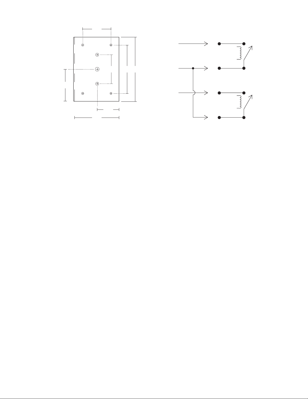
BLACK
LOAD
RELAY
1.8” 3” 4”
2”
RED
BLUE
1.35”
2.75”
Figure 1: Mounting dimensions
Figure 2: Relay connections
INJECT
RELAY
Basic Connections
1. Connect the air lines betw een the DVI and the air actuator as shown in Figure 3 on the back page.
2. Connect the air supply line to a regulated source of compressed air or nitrogen. (60-80 psi recommended, 100 psi maximum)
3. Connect the tr ansformer to the DVI as indicated, and plug it in.
Manual Operation
No additional installation is required for use of the three position switch on the front panel of the DVI.
The manual switch will override automatic operation unless the operation is controlled by a single
double throw relay.
Automatic Operation
The D VI can be controlled b y one doub le throw relay, two single throw relays, or remote negative true
logic. The input signals to the DVI can be continuous or as short as fifty milliseconds. Any unused
wires should be taped or tied out of the way.
One relay operation (double throw)
1. Connect the BLACK (LOAD) wire from the DVI to the Normally Closed (N.C.) relay contact.
2. Connect the RED (ground) wire to the Common (Com/Grnd) relay contact.
3. Connect the BLUE (INJECT) wire to the Normally Open (N.O.) relay contact.
Two relay operation
1. Connect the RED (ground) wire from the DVI to the common of both relays.
2. Connect the BLACK (LOAD) wire to the Normally Open (N.O.) contact of the relay designated for
the LOAD position.
3. Connect the BLUE (INJECT) wire to the Normally Open (N.O.) contact of the relay designated for
the INJECT position.
Page 3

Operation by Remote Negative True Logic
1. Connect the RED (logic g round) wire from the DVI to the logic ground of the timing device . (Consult
its manual as necessary.)
2. Connect the BLACK (LOAD) wire from the DVI to the output chosen for the LOAD position.
3. Connect the BLUE (INJECT) wire from the DVI to the output chosen for the INJECT position.
Use of Remote LEDs
1.Connect the positive (+) leg of the LEDs to the grey wire of the interface cable.
2. Connect the other legs from the LEDs to the VIOLET wire for the LO AD indicator and to the GREEN
wire for the INJECT indicator.
INPUT (LOAD)
CONTACT CLOSURE 2
LED DRIVE +
LED 2 (LOAD)
INPUT (INJECT)
LED 1 (INJECT)
CONTACT CLOSURE 1
CONTACT CLOSURE 2
LOGIC GROUND
CONTACT CLOSURE 1
BLACK
WHITE
GREY
VIOLET
BLUE
GREEN
YELLOW
ORANGE
RED
BROWN
NOTE:
ALL INPUTS ARE 5 VOLT NEGATIVE TRUE LOGIC
1.
INPUTS REQUIRE .5 MILLIAMPERES DRIVE
2.
INPUTS MUST HAVE A CLOSURE TO LOGIC GROUND - (RED) TO ACTUATE
3.
DIGIT AL V AL VE
INTERF ACE (D VI)
CONNECTION FOR
LOAD POSITION
VALCO TWO POSITION
AIR ACTUATOR
CONNECTION FOR
INJECT POSITION
POWER SUPPLY
TRANSFORMER
Figure 3: D VI connections
North America, South America, and Australia/Oceania contact: Europe, Asia, and Africa contact:
®
Valco Instruments Co. Inc.
P. O. Box 55603
Houston, TX 77255
Sales toll-free (800) 367-8424
Technical help
Fax (713) 688-8106
(713) 688-9345
valco@vici.com
®
VICI AG International
Parkstrasse 2
CH-6214 Schenkon
Switzerland
Phone (Int + 41 + 41) 925-6200
Cheminert® and VICI® are registered trademarks of Valco Instruments Co . Inc. and VICI AG
Fax (Int + 41 + 41) 925-6201 info@vici.ch
AIR IN
(100 psi MAX)
TN-411 8/04
 Loading...