

Page 1
Analytical
Components
Systems
&
Pulsed Discharge Detector
Model D-4-I
Quick Reference Guide
General Precautions:
• Never run the detector without discharge gas. To insure a continuous supply of discharge gas, always
change the gas bottle when it reaches 500 psi.
• Never bake out a column while it is connected to the detector.
• Detector lifetime is shortened in the Ar/Kr PID mode. To maximize detector lifetime, turn off the discharge
power when the GC is not actually analyzing samples.
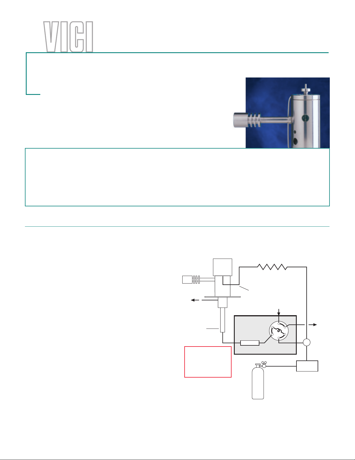
Gas connections
Detector performance is adversely affected by the
presence of impurities in the gas stream. To minimize
the chance of this occurring:
1. Always use the helium purifier.
2. Never use copper or plastic tubes,
even before the helium pur ifier.
3. Never use flow controllers containing
polymers or lubricant.
4. Never use pipe fittings or teflon tape
downstream of the purifier.
You will need:
• Helium
99.9999% purity (“six nines”)
Air Liquide part number:
• Gas regulator
Ultrahigh purity, with stainless steel
diaphragm
Valco part number:
•
Valco Helium Purifier
(included with the detector system)
Valco part number:
• Stainless steel tubing and
Fittings with gold ferrules
(consult the Valco catalog)
• Restrictor
(included with the detector system)
Valco part number:
ValGas 4
TGA-422-580
HP2
TGA-R-30F60P
VENT
COLUMN
INLET
Leave column inlet
plugged until flow
rate is set. (See
“Initial Power-Up”
on next page.)
DISCHARGE GAS
COLUMN
GAS CHROMATOGRAPH
(99.9999% He)
TGA-R-30F60P
RESTRICTOR
(30 mL/min minimum)
DISCHARGE GAS
INLET
SAMPLE
IN
HELIUM
PURIFIER
VENT
TEE
(ZT1)
Page 2
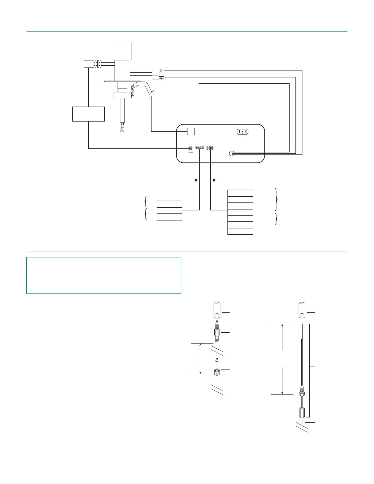
Electrical Connections
HIGH
VOLT AGE
PULSER
MODULE
(no connection)
HEATER CABLE
FROM DETECTOR
BIAS-B
ELECTROMETER
BIAS-A
CONTROLLER
(Rear panel)
RECORDER
ATTENUATED
OUTPUT
SHIELD
+
–
RED
BLACK
GREEN
WHITE
Initial Power-Up
Caution:
•
Always make sure that discharge gas is
flowing before heating and powering up
the detector.
1. Before installing the column, set the gas flow to
30 ml/min (measured at the detector vent). Let it
flow for 15 minutes so that all air is purged from the
helium purifier.
2. Plug in the helium purifier.
3. Install the column as illustrated at right.
4. Turn on the MAINS switch on the back of the
controller. Set the MODE switch on the front
panel of the controller to PDHID.
5. Set the detector temperature and allow time for
the detector and helium purifier to reach the set
temperature.
6. Turn on the DISCHARGE switch on the front panel
of the controller.
TO
11.4 cm
TO COMPUTER
OR INTEGRATOR
RED
BLACK
WHITE
GREEN
BROWN
BLUE
ORANGE
YELLOW
COLUMN
INLET
CAPILLARY
COLUMN
ADAPTER
(IZERA1.5)
COLUMN
FERRULE
NUT
CAPILLARY
COLUMN
0 - 10 V
Common
0 - 1 V
Shield
COM
SET
UNATTENUATED
OUTPUT
AUTO
ZERO
9.8 cm
(set at the
factory)
COLUMN
INLET
PACKED
COLUMN
ADAPTER
(I-23642-D4RU)
The discharge should start within five minutes. In a
clean system, the discharge will have a peach/pink color.
A purple discharge indicates leakage or impurities in the
system.
7. Check the standing/background current on the
controller display. Optimum current is 1.0 - 2.5 nA.
PACKED
COLUMN
Page 3

Troubleshooting
•
High Background Current
Disconnect the column
and cap the column inlet
Pink
Check
discharge
color
•
Low Sensitivity
Check background current
with column removed and
column inlet plugged
Purple/
blue
Do a hydrogen leak test
(described on last page)
Baseline current falls to
normal range (£ 2.5 nA)
Baseline current is still high
(> 2.5 nA)
Leaks in the fittings of the
PDD plumbing
Leaks inside the detector
cell itself
No detectable leaks.
The detector isn’t leaking.
Check for column bleed
and/or leaks in the GC setup.
Tighten leaking fittings
Consult
Valco
Possible bad carrier gas
or empty He bottle. Install
a new bottle.
Baseline current falls to
normal range (£ 2.5 nA)
Baseline current is still high
(> 2.5 nA)
Baseline current falls to
normal range (£ 2.5 nA)
Baseline current is still high
(> 2.5 nA)
Baseline current falls to
normal range (£ 2.5 nA)
Baseline current is still high
(> 2.5 nA)
Consult
Valco
Consult
Valco
Consult
Valco
Sensitivity is in
acceptable range
High background current
(> 2.5 nA)
Refer to “Troubleshooting:
High Background Current”
•
No Peaks
Normal background current
(£ 2.5 nA)
Reinstall column and check
background current
Background current
increases
Background current
remains in normal range
If the background current is stable but there are no peaks:
1. Check column flow.
2. Check the column insertion position (11.4 cm for
capillary columns, 8.9 cm for packed columns).
3. If there are still no peaks, check to make sure that
the GC is actually making an injection.
4. If there are still no peaks, consult Valco.
Check column inlet for
leaks. Tighten fittings.
Check column position
according to drawing on
page 2, and run a sample.
Background current
remains high
Background current
drops to normal range
Sensitivity is in
acceptable range
Sensitivity is still
too low
Remove column and
condition it, then run
a sample
Run
a sample
Remove column and
bake detector at
300°C for four hours.
Install column and run
a sample.
Sensitivity is still
too low
Sensitivity is in
acceptable range
Sensitivity is still
too low
Sensitivity is in
acceptable range
Sensitivity is still
too low
Consult
Valco
•
High Noise Level
If the noise level is high:
1. See if it improves with the GC fan turned off.
2. Check the column insertion position (11.4 cm for
capillary columns, 8.9 cm for packed columns).
3. If the noise level is still high, do a hydrogen leak test
(described on the next page).
4. If there are no leaks found, or leaks are found and
repaired and the noise is still high, consult Valco.
Page 4

Hydrogen Leak Test
A hydrogen leak test allows you to pinpoint loose fittings
and leaks inside the detector.
1. Connect a length of plastic tubing to a regulated
hydrogen bottle. Establish a flow of 5 -10 ml/min.
2. Hold the hydrogen outlet tube at a fitting connection for ten seconds while monitoring the
baseline. (Flip the mode switch to PDECD and
back to PDHID to un-zero the baseline.)
If the baseline stays the same, that connection is
leak-free. If the baseline goes up, you have
located a leak.
3. Tighten the fitting and test it again, repeating as
necessary until every connection has passed the
ten second test.
4. If the current remains high, hold the hydrogen
outlet close to the detector.
tube into any detector holes.)
detector is indicated, contact Valco.
(Do not insert the
If a leak in the
Valco Instruments Co. Inc. Valco International
tel: 800 367-8424
fax: 713 688-8106
valco@vici.com
tel: Int + 41 41 925-6200
fax: Int + 41 41 925-6201
vici@vici.com
Printed in USA © 2003
VICI® and Cheminert
are registered trademarks of
Valco Instruments Co. Inc. and VICI AG
7/03
®
 Loading...