

Vichy VC99 User Manual
User’s manual for VC99 3 6/7 DMM
1.SUMMARY
This digital multimeter is a steady performance, battery-driven 3 6/7 digital multimeter.
It uses the LCD with 23mm-high figure to make the reading clear and make operation more
convenient.
The digital multimeter has the function of measuring DCV, ACV, DCA, ACA, resistance,
capacitance, frequency, temperature, duty cycle, transistor and diode, continuity performance
test .The meter can provide functions including analog bar and unit symbol display, data
holding, relative value measuring, maximal/minimal value measuring, auto/manual range
switching (RANGE), auto power off and warning functions .it adopts double integral A/D
converter as its core. It is an ideal tool for labs, factories and radio-technology.
2.SAFTY NOTES:
The instrument is designed according to IEC1010 standard (safety standard issued by
International Electro technical Committee). Please read the following before operation.
1-1.Check the connection and insulation of test leads to avoid electric shock.
1-2.Do not input a limited voltage higher than DC 1000V or AC 750V when measuring ranges.
1-3.When measuring voltage higher than DC 60V, AC 40V, please be careful.
1-4. Select correct function and range to avoid fault operation.
1-5.Please move the test leads away from test points when switching the function.
1-6.Please don’t input voltage value when measuring current.
1-7.Please don’t modify the circuit.
1-8.Introduction for safety symbol:
“ ” exists high voltage; “ ” GND “ ” dual insulation “ ” must refer to
manual “ ” Low battery.
3. SPECIFICATION
1. General features
1-1. Displaying: LCD;
1-2.Max display: 6000(3 6/7) digits automatic polarity, unit symbol and 61 section analog
display;
1-3. Measurement method: double integral A/D conversion;
1-4. Sampling rate: approx.3 times/sec.
1-5. Over-range display: “OL” displayed in the highest digit.
1-6. Low battery display:“ ”
1-7. Working environment: (0~40)℃, relative humidity: <80%;
1-8.Store environment: (-10~40)℃, relative humidity: <80%;
1-9.Power supply:2pcs 1.5V battery(“AAA”7# battery);
1-10. Dimension: 185×93×35mm (length*width*height);
1-11. Weight: approx..290g((including battery);
1-12.Accessories: test leads, user manual, temperature probe, holster, gift box, and 2*1.5V
battery.
2. TECHNICAL FEATURES
2-1. Accuracy: ± (a% × reading data + digits), environment temperature at (23±5) ℃, relative
humidity<75%, One year guarantee since production date.
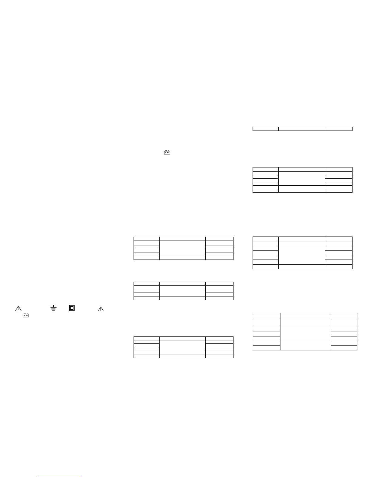
2-2.DC Voltage(DCV)
Range
Accuracy
Resolution
600mV
±(0.5%+3)
0.1mV
6V
1mV
60V
10mV
600V
100mV
1000V
±(0.8%+3)
1V
Input impedance: approx. 10MΩ
Overload protection:1000V DC or 750V AC.
2-3.AC Voltage(ACV)
Range
Accuracy
Resolution
6V
±(0.8%+5)
1mV
60V
10mV
600V
100mV
750V
±(1.0%+5)
1V
Input impedance: approx. 10MΩ
Overload protection:1000V DC or 750V AC.
Frequency response:(40~200)Hz under 750V ,other range:(40~400)Hz.
Sine wave RMS(Average value response).
2-4.DC Current(DCA)
Range
Accuracy
Resolution
600uA
±(1.0%+3)
0.1μA
6000uA
1μA
60mA
10μA
600mA
100μA
6A
±(2.0%+5)
1mA
20A
10mA
MAX measurement voltage drop::full range mA :300mV,A:100mV。
Max input current: 20A (within 15 seconds)
Over load protection: 500mA/ 250V and 13A/250V
fast molten fuse.
2-5.AC Current(ACA)
Range
Accuracy
Resolution
600uA
±(1.2%+5)
0.1μA
6000uA
1μA
40mA
10μA
600mA
100μA
6A
±(2.0%+15)
1mA
20A
10mA
MAX measurement voltage drop::full range mA :400mV,A:200mV。
Max input current: 20A (within 15 seconds)
Over load protection: 500mA/ 250V and 13A/250V
fast molten fuse.
Frequency response:: 20A range:40~100Hz,other range:40~400Hz。
2-6.Resistance(Ω)
Range
Accuracy
Resolution
600Ω
±(0.8%+5)
0.1Ω
6kΩ
±(0.8%+3)
1Ω
60kΩ
10Ω
600kΩ
100Ω
6MΩ
1kΩ
60MΩ
±(1.2%+5)
10kΩ
Open circuit voltage::600mV
Over load protection: 250V DC or AC peak value;
NOTE: At range 600 Ω, short-circuit the test leads to measure the wire resistance and then
subtracts it from the real measurement. Or press “”REL” to clear the wire resistance and read
the value directly.
2-7.CAPACITANCE(C)
RANGE
ACCURACY
RESOLUTION
40nF
±(2.5%+6)
10pF
400nF
±(2.5%+5)
100pF
4μF
1nF
40μF
10nF
400μF
±(5.0%+8)
100nF
2000μF
1uF
Overload protection :250V DC or AC peak value.
2-8.REQUENCY(F)
RANGE
ACCURACY
RESOLUTION
10Hz
±(0.5%+4)
0.01Hz
100Hz
0.1Hz
1000Hz
1Hz
10kHz
10Hz
100kHz
100Hz
1MHz
1kHz
60MHz
10kHz
Input sensitivity:0.7V
Over load protection: 250V DC or AC peak value;
2-9.Transistor(hFE)
RANGE
VALUE
TESTING CONDITION
NPN OR PNP
0~1000
Basic current approx.15μA,
Vce approx.4.5V
2-10. Diode and continuity performance test
range
VALUE
TESTING CONDITION
Forward voltage drop of diode
Forward DCA is approx. 0.5mA,
the backward voltage is approx
1.5V
Buzzer makes a long sound while
resistance is less than (50±10)Ω
Open circuit voltage is approx.
0.5V
Over load protection: 250V DC or AC peak value;
CAUTION:DO NOT INPUT VOLTAGE AT THIS RANGE!
2-10. TEMPERATURE(℃)
RANGE
VALUE
RESOLUTION
-40℃-1000℃
<400℃ ±(0.8%+4)
≥400℃ ±(1.5%+15)
1℃
0F-1832℉
<750℉ ±(0.8%+5)
≥750℉ ±(1.5%+15)
℉
Sensor:TP01(K type thermocouple)
CAUTION:DO NOT INPUT VOLTAGE AT THIS RANGE!
4. OPERATION
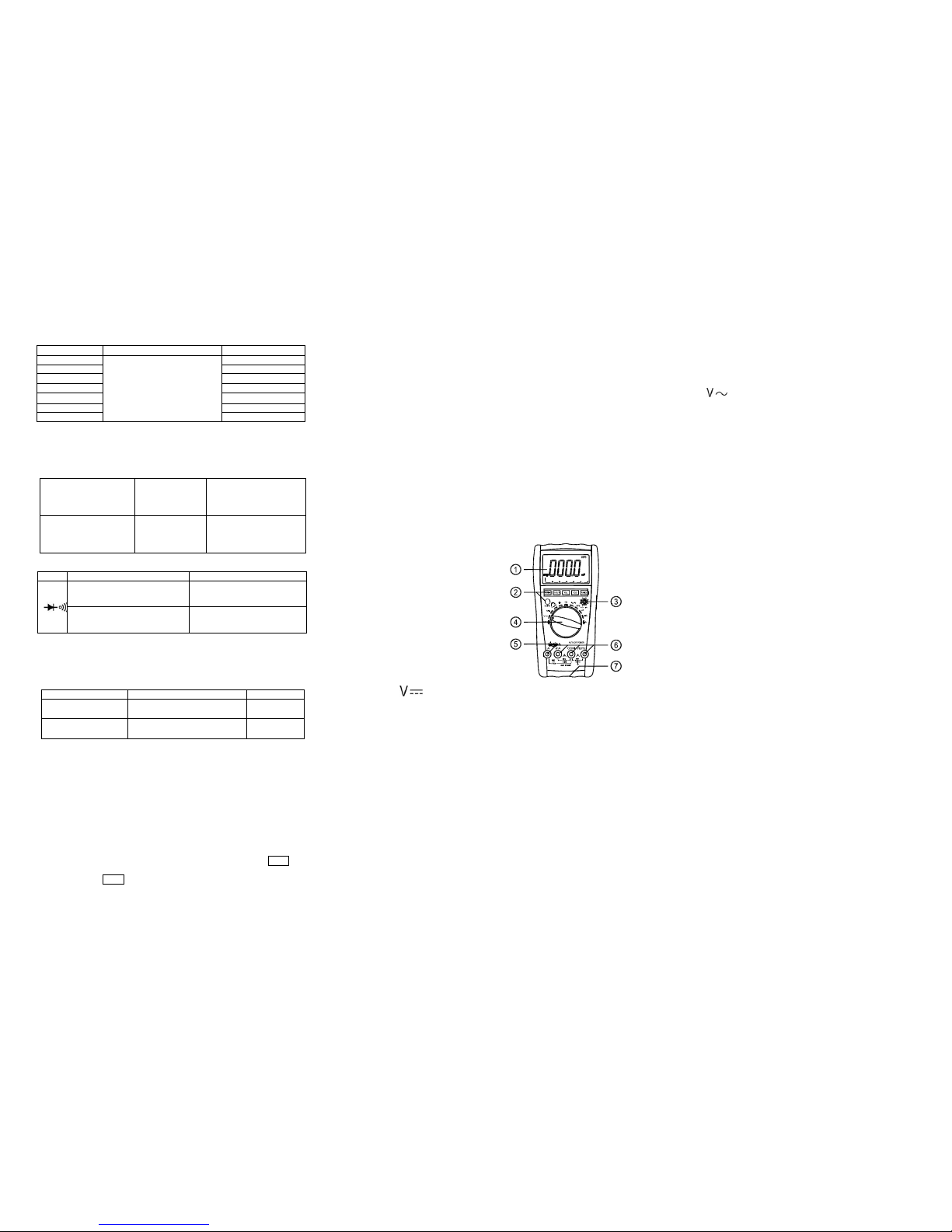
4-1. Panel description
1. LCD: display the measuring value and unit.
2.Function key:
2-1.HOLD key:press it, the presently measured value is held on LCD and HOLD symbol
displays. Press it again, HOLD symbol disappears, and the meter is exited the holding mode.
2-2. REL key:press it,reading clear,turn into relative value measurement states,“REL”symbol
displays, Press it again,“REL” symbol disappears, and the meter is exited the relative mode.
2-3. Hz/DUTY key:When measuring the AC Voltage (Current),press it,it will switch
Frequency/duty cycle/Voltage(Current), When measuring the Frequency ,it will switch
frequency/duty cycle(1~99%)。
2-4.”DC/AC”key: switch DC and AC work mode..
2-5.RANGE key:select auto range or manual range mode, Auto range is the original states, it
will display ”AUTO” symbol ,press it change to manual range .Press it more than 2 second , it
will return to auto range states
2-6.MAX/MIN key :press it, turn into MAX mode, it will hold the max value of measuring,
press it again ,turn into MIN mode, it will hold the min value of measuring. No auto power off
and analog bar display under this mode. Press it more than 2 second , it will exit MAX/MIN
states.
3. hFE transistor COM
4. Knob:Switch measuring function and range.
5. Temperature COM
6. Voltage、Current、resistance、frequency and GND
COM.
7.battery case.
See picture 1
4-2.DCV measuring
1.Select the knob to range.
2. Insert the black test lead to “COM” terminal and the red one to “V/Ω/Hz” terminal.
3.Auto range is the original states, it will display ”AUTO” symbol,pre ss “RANGE” key
change to manual range mode,600mV、6V、60V、600V、1000V range is selective;
4. Connect the leads crossly to the electric circuit under test; LCD displays polarity and voltage
under test connected by the red test lead.
Note:
1. Firstly users should select the knob to the highest range, if users had no idea about the range
of voltage under test, and then select the proper range based on displaying value. If LCD
displays “OL”, it means meter is over the max. Value of this range, thus should select the knob
to a higher range.
2. Do not input a voltage over DC 1000V.
3. Be carefully while measuring a high voltage. DO NOT touch the high voltage circuit.
4.When the measuring voltage large than DC1000V ,the built –in buzzer will be sounds.
4-3.ACV measuring
1.Select the knob to “ ” range;
2. Insert the black test lead to “COM” terminal and the red one to “V/Ω/Hz” terminal.
3. Auto range is the original states, it will display ”AUTO” sy mbol,press “RANGE”key
change to manual range mode,6V、60V、600V、750V range is selective;
4. Connect the leads crossly to the electric circuit under test, LCD displays voltage by the test
lead.
Note:
1. Firstly users should select the knob to the highest range, if users had no idea about the range
of voltage under test, and then select the proper range based on displaying value. If LCD
displays “OL”, it means meter is over the max. Value of this range, thus should select the knob
to a higher range.
2. Do not input a voltage over AC 750V.
3. Be carefully while measuring a high voltage. DO NOT touch the high voltage circuit.
4.When the measuring voltage large than AC750V ,the built –in buzzer will be sounds.
4-4.DCA measuring
1.Insert the black test lead to “COM” terminal and the red one to “mA” ter minal (the Max.
600mA) or to “20A”(the Max.20A);
2.Select the knob to a proper DCA range, press “DC/AC” key to select the measurement mode,
then connect the leads crossly to the electric circuit under test; LCD displays polarity and
current under test connected by the red test lead.
Note:
1. Firstly users should select the knob to the highest range, if users had no idea about the
range of current under test, and then select the proper range based on displaying value .
2. If the LCD displays “OL”,it means the current is over range. Now you need to select the
knob to the higher.
3. Max. input current is 600mA or 20A(subject to where the red test lead insert to), too
large current will damage the fuse.
4-5.ACA measuring
 Loading...