

Vichy VC97 Operation Manual
DIGITAL
DIGITAL
DIGITAL
MULTIMETER
MULTIMETER
MULTIMETER
OPERATION
OPERATION
OPERATION
MANUAL
MANUAL
MANUAL
1.1.1.
INTRODUCTION
INTRODUCTION
INTRODUCTION
The instrument is a high performance, high accuracy , 33/4digit , 42mm digit
high LCD multi-meter for measuring DC and AC voltage, DC and AC current,
Resistance and Capacitance, Frequency, temperature, duty circle, Transistor, Diode
and Continuity test. Design parameter: unit indication, data hold (HOLD), relatively
measuring (REL), AUTO/MANUAL range, auto off and buzzer sou nds, etc.
The Dual-slop A/D converter CMOS technology for auto-zero, polarity
selection and over-rang e indication. Full overload protection is provided. Because
of its outstanding features, it is most suitable for use on production lin es or for lab,
R & D, m ainten ance and repair work.
222
.SPECIFICATIONS
.SPECIFICATIONS
.SPECIFICATIONS
2.1
2.1
2.1
GENERAL
GENERAL
GENERAL
SPECIFICATIONS
SPECIFICATIONS
SPECIFICATIONS
Display: 3 3/4digit LCD with a max readings of 3999
Measuring method: Dual - slop integrating A/D converter system.
Sampling rate: Approx. 3times/second.
Max. Common Mode Voltage: 500V DC/AC RMS.
Range select method: Automati c and Manual
Polarity: Automatic negative polarity indication.
Over range indication: Only the MSD “ OL ” display.
Low battery:The “ ” displays .
Safety standards
:
EMC/LVD. The meter is up to the standards of IEC1010
Pollution Degree 2, Over vol tage category Ⅱ or double insulation Ⅱ .
Operating environment: Temperature (0 ~ 40) ℃ , humidity<80%RH.
Storage environment: Temperature (-10~50) ℃ , humidity<80%RH.
Power: Double, standard 1.5 volt battery. AAA 7# battery.
Dimension: 190mm (H) × 93.5 mm (W) × 3 7m m (D).
Weight: Approx. 4 20g(including battery).
2.2
2.2
2.2
ELECTRICAL
ELECTRICAL
ELECTRICAL
SPECIFICATIONS
SPECIFICATIONS
SPECIFICATIONS
Accuracy is ± (percent age of reading + number of digit) at(23 ± 5) ℃ ,<75%RH .
DCDCDC
Voltage
Voltage
Voltage
Input impedance: 400mV range: more th an 40M Ω other ran ge: 10M Ω
Overload protection: 1000V DC or AC peak value
DCDCDC
mVmVmV
:::
ACACAC
Voltage
Voltage
Voltage
Input impedance: 400mV range: m ore th an 40M Ω ; other range: 10M Ω
Frequency response: 750V range:40-100Hz oth er range: 40-400Hz
Overload protection: 1000DC/750V AC RMS
Indication
:
mean val ue response ( rms of sine wav e)
Range
Accuracy
Resolution
400mV
± (0. 5 %+4d)
0.1mV
4V
1mV
40V
1 0 mV
400V
1 00 mV
1000V
± (1.0%+ 6 d)
1V
Range
Accuracy
Resolution
400mV
± ( 0.5 %+ 4 d)
0.1mV
Range
Accuracy
Resolution
4V
± ( 0. 8%+ 10 d)
1mV
40V
1 0 mV
400V
1 00 mV
7 50V
± (1.0%+ 10 d)
1V
Resistance
Resistance
Resistance
Overload protection:250V DC/AC peak value
Open ci rcuit v oltage: 400mV
Note: at 400 Ω rang e, should short the test leads and m easure the resi stance of the wire,
then, minus from measuring.
DCDCDC
Current
Current
Current
Overload protection : 0.5A/250V fuse, 10A/ 250 V fuse.
Max measuring voltage: Full scale mA ran ge: 1.2V ; A range:100
mV.
Max input current: 10A ( max. up to 15 seconds).
ACACAC
mVmVmV
ACACAC
Current
Current
Current
Overload protection : 0.5A/250V fuse, 10A/250 V fuse
Max measuring voltage: Full scale mA ran ge: 1.2V A ran ge: 100 mV
Max input current: 10A (up to 15 seconds).
Frequency response: 1 0A range: 40-100Hz; other range: 40-400Hz
Capacitance
Capacitance
Capacitance
Overload protection : 250V DC/AC peak value
Frequency
Frequency
Frequency
Input sensitivity: 1.0V
Range
Accuracy
Resolution
400 Ω
± (0. 8 %+5d)
0.1 Ω
4k Ω
± (0.8%+4d)
1 Ω
40k Ω
10 Ω
400k Ω
100 Ω
4M Ω
1k Ω
40M Ω
± (1.2%+ 10 d)
10k Ω
Range
Accuracy
Resolution
400u A
± ( 1.0 %+ 10 d)
0.1u A
40 0 0u A
1u A
40m A
± ( 1.2 %+ 8 d)
10 u A
40 0 m A
100 u A
10A
± (1.2%+10d)
1 0 m A
Range
Accuracy
Resolution
400 mV
± ( 1.6 %+ 8 d)
0.1 mV
Range
Accuracy
Resolution
400u A
± ( 1.5%+10d)
0.1u A
40 0 0u A
1 u A
40m A
10 u A
40 0 m A
100 u A
10A
± (2.0+15d)
1 0 m A
Range
Accuracy
Resolution
4n F
± ( 2 .5%+ 20 d)
1 pF
40n F
± (3.5%+8d)
1 0pF
40 0 n F
100pF
4uF
1nF
40uF
10nF
200uF
± (5 .0 %+ 10 d)
100 n F
Range
Accuracy
Resolution
100Hz
± ( 0. 5% + 10 d)
0.01Hz
1000Hz
0.1Hz
10kHz
1Hz
100kHz
10Hz
1MHz
100Hz
30MHz
1kHz
Overload protection: 250V DC/A C peak value
Diode
Diode
Diode
and
and
and
continuity
continuity
continuity
Test
Test
Test
Overload Protection:250V DC/AC peak value
Warning: do not i nput volt age at the range for safety.
Transistor
Transistor
Transistor
hFE
hFE
hFE
Test
Test
Test
Temperature
Temperature
Temperature
Thermocouple: K type
Warning: do not i nput volt age at the range for safety.
3.3.3.
FRONT
FRONT
FRONT
PANEL
PANEL
PANEL
DESCRIPTION
DESCRIPTION
DESCRIPTION
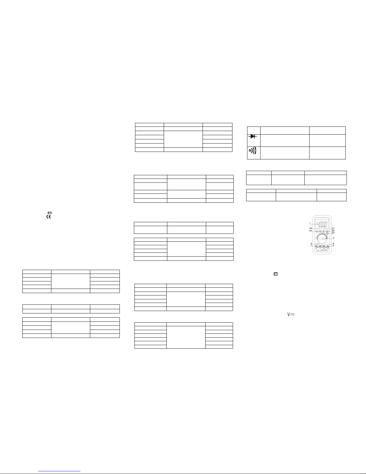
1.LCD
2. Fu nction key
2-1.HOLD Key
2-2.REL Key
2-3.Hz/DUTY Key
2-4 “ select ” key
2-5.RANGE Key
3.Rotary Switch
4.Vol tage, Resistance, Frequency socket.
5.COM input jack term inal
6.Less than 400mA input jack terminal
7.10A input jack terminal
4.OPERATION
4.OPERATION
4.OPERATION
1.Check the 1.5 -volt b atterybysetting the ROTAR Y Switch remove s to OFF position.
If the battery is weak, a sign will appear on the display. If thi s does n ot appear on
the display, proceed as below . See MAINTENANCE if the battery has to be replaced.
2.The mark, or sig n next to the l ead jacks, is for warning that the input voltage or
current should not exceed th e indicated values.
This i s to prevent fr om damaging the internal circuits.
3.The function switch should be set to the range that you want to test before operation.
444
.1.1.1
DCDCDC
Voltage
Voltage
Voltage
measurement
measurement
measurement
1) Insert the BLACK test lead to “ COM ” jack and RED test lead to the “ V/ Ω /H z ”
jack.
2 ) Set t he FUNCTION switch to “ ” ran ge.
3) The d efault rang e is Auto range, and "AUTO" is displayed. Pressing RANGE k ey
switch to m anual range, 400m V/4V/40V / 400V/1000V can be select ed
.
4) Conn ect the test leads to the tested point, the voltage and polarity wh ich connected
with the red l ead will appear o n L CD.
Note:
Note:
Note:
1) Manual range, if LCD display "OL", over rang e i s being indicated and the
FUNCTION switch must be set to a h igher ran ge.
2) D o not measure over 1000V , or , the meter will be damaged.
3) Caution to avoid contact with high voltage circu its when measuring high v oltage.
Range
Description
Test Condition
Display read approx. forward
voltage of diode
Forward DC Current
approx.0.5mA. Reversed
voltage approx.
1.5V.
Buzzer sounds i f resistance
Between terminals V/ Ω a n d COM
is less than about 7 0 ± 30 Ω .
Open circuit voltage:
0.5V
Range
Displaying value
Test condition
hFE NPN or
PNP
0 ~ 1000
Base Cu rrent ap p rox.
15uA, Vce approx . 1.5V
Range
Displaying value
Test condition
(- 2 0-1000) ℃
<<<
400 ℃ ± ( 1.0 %+ 5 d)
≥ 400 ℃ ± (1.5%+15d)
1 ℃

444
.2.
.2.
.2.
ACACAC
voltage
voltage
voltage
measurement
measurement
measurement
1) Insert the black test lead to “ COM ” jack an d the red one to “ V/ Ω /Hz ” jack.
2) Set the fu nction switch to “ ” ran ge.
3) The defau lt range is Auto range, and "AUTO" is d isplayed. Pressing RANGE
key swit ch to m anual range, 400m V/4V/40V / 400V/700V can be select ed
.
4) Connect the test leads to the test point, the voltage of the two points which
connected with the leads wil l appear on L CD.
444
.3.3.3
DCDCDC
Current
Current
Current
measurement
measurement
measurement
1) In sert the BLACK test lead to “ COM ” jack and RED test lead to the “ mA ” (max .
400mA) or "10A" jack (max. 10A).
2 ) Set the FUNCTION switch to current range. Pressing “ ” key to select
DC measure method , conn ect the leads across to the tested ci rcuit, the current
value and pol arity the red lead connect with will appear on LCD.
Note:
Note:
Note:
1) If the current range is un known beforehand, set the FUNCTION switch to a
high range and work down.
2) When o nly the figure " OL " is displayed over range is being indicated and the
FUNCTION switch must be set to a h igher ran ge.
3) The max input current is 400mA,or 10A depending u pon the jack used.
Excessive current will blow the fuse.
444
.4.
.4.
.4.
ACACAC
current
current
current
measurement
measurement
measurement
1) Insert the BLACK test lead to “ COM ” jack and RED test l ead to the mA ” (max.
400mA) or "10A" jack (max. 10A).
2 ) Set the FUNCTION switch t o current rang e. Pressing “ ” key t o select
AC measure method , conn ect the leads across to the tested ci rcuit, the current
value will appear on LCD.
Note:
Note:
Note:
1) If the current r ange is unkn own beforehand, set the FUNCTION switch to a high
range and work down.
2) When only the figure " OL " i s displayed over range is being indicated and th e
FUNCTION switch must be set to a h igher ran ge.
3) The max input current is 400mA,or 10A depending u pon the jack used.
Excessive current will blow the fuse.
444
.5.5.5
Resistance
Resistance
Resistance
measurement
measurement
measurement
1) Connect the BLACK test lead to “ COM ” jack and RED test l ead t o the “ V/ Ω
/Hz ” jack.
2 ) Set t he FUNCTION Switch to “ Ω ” range.
3) Press "RANGE" to select A uto/Manual range
4) If measuring small resistance, should short test leads f irst, press "REL" on ce,
ensure measure v alue accuracy .
Note:
Note:
Note:
1)Touse manual method, i f the resistance range is unknown befor ehand, set the
FUNCTION switch to a higher range and work down.
2 ) If "OL" displays on LCD, i t means over-range. When m easuring resistance more
than 1M Ω , the meter may t ake a few seconds to stabilize. This is n ormal for
high resistance readings.
3) When the input is not con nected, i.e. at open circuit , the fi gure " OL " will be
displayed for the over range condition.
4) When checking in-circuit resistance, be sure the power has be en switched off
all
capacitors are fully di scharged.
5 ) D o not input any voltage at this range.
444
.6.6.6
Capacitance
Capacitance
Capacitance
measurement
measurement
measurement
1) Set the FUNCTION switch t o " " position.
2) Press "REL" once t o adjust to zero.
3 ) Connect the tested capacitor to “ COM ” , “ V/ Ω /Hz ” input sockets in
accordance to the leads (the polarity of the red lead is “ + ” ), the value wil l be
displayed on LCD.
4) When m easuring more than 4u F, it takes 15 seconds to stabili ze.
Note:
Note:
Note:
1) Capacit ance range h ave only auto mode.
2) Before measuring each time, m ust press "REL" to ensure m easure accur acy.
3) Units: 1u F=1000nF 1nF=10 00p F
4) Capaci tors should be fully discharged to avoid damaging the mete r.
444
.7.7.7
Frequency
Frequency
Frequency
measurement
measurement
measurement
1) Connect test leads or shield cable to "COM" and "V / Ω /Hz " jack.
2) Set the FUNCTION switch to the "Hz" range, and connect test l eads or c able
across th e source load under test.
3)
Press "Hz/Duty" to switch f requency/duty cycle, and display the reading of
frequency or duty cycle.
Note:
Note:
Note:
1) F requency rang h ave only auto range m ode.
2) D o not a pply more than 250V DC/AC peak value t o the in put. Indication is
possible at voltage higher than 10V AC rms, but readings may be out of
specification.
3) In noisy environment, it i s preferable to use shield cable for measuring small
signal.
4) Be caution to avoid contact with high tension circuits when measurement high
voltage.
444
.8.8.8
hFE
hFE
hFE
measurement
measurement
measurement
1) Set th e function switch to hFE range.
2 ) Define the transistor is NPN or PNP type, insert the emitter, base and collector
separately t o the correct hole, the approx. value will be displayed on LCD.
444
.9.9.9
Diode
Diode
Diode
and
and
and
continuity
continuity
continuity
Test
Test
Test
1) Connect the BLACK test lead to “ COM ” jack and RED test lead to the “ V Ω Hz ”
jack..
2 ) Set th e FUNCTION switch to “ ” position. Pr ess " DC/AC " k ey which
select diode measure method.
3) Forward m easure: Connect RED test lead to the posi tive of th e test di ode,
BLACK test lead to the negative, then, reading of a pprox. forward voltage of
this diode displays.
4) Reverse m easure: Con nect BLACK test lead to the positive of the test diode,
RED test l ead to the negative, the mark "OL" will be displayed.
5) P roper diode testing should include both steps.
6) Press " " to select con tinuity mode.
7) Connect the test probes to two points of circu it, if the resistance is lower than
approx. 50 ± 20 Ω.Buzzer soun ds.
Note:
Note:
Note:
Do not i nput volt age at this range.
444
.10
.10
.10
Temperature
Temperature
Temperature
measurement
measurement
measurement
1.
Set the function key to “ ℃ ” range.
2.
Insert the cold-point of the thermocouple to “ K TEMP ” hole, and the work-point
to the place wanted to take temperature, the value will be displayed o n L CD.
NOTE:
NOTE:
NOTE:
1.
When the input terminal is in open ci rcuit, wi ll display the “ normal temp. ”
2.
Do not ch ange the thermocouple, or, the accuracy can not be secured.
3.
Do not i nput volt age at this range.
444
.1.1.1
111
Data
Data
Data
hold
hold
hold
Press “ Hold ” key, the current data will d isplay on LCD; Press the key again, will
cancel the hold function.
4.4.4.
111
222
Auto
Auto
Auto
power
power
power
off
off
off
1) Stop w orking for 15m ins, the instrument is auto off and in to the sleep mode. The
buzzer wil l sound before power
off.
Press any key to turn on th e power.
2 ) Pressi ng “ ” key before tur ning on c an cancel the function.
555
...
WARNING
WARNING
WARNING
1) When m easuring voltage ensure that instrument is not connected or switched to a
current or resistance range, or t o the diode check. Always ensure that the correct
terminals are used for the ty pe of mea surement to be made.
2) Take extreme care when measuring v oltage above
50V,
especially from sources
where high energy i s existed.
3) Av oid m aking conn ections t o “ live ” circuits whenever possible.
4) When making current measurements ensure that the circuit not “ live ” bef ore
opening it in order to connect the test leads.
5) Before making resi stance measurements or diode test, ensure that the ci rcuit
under test is de-energized.
6) Always ensure that the correct function and range is selected. If in doubt about
the correct rang e t o use, start wi th the highest and work downwards.
7) Extreme care should be taken when using the instrument to conj unction with a
current transformer connected t o the termin als if an open circuit occurs.
8) Ensure that th e test leads and probes are good condi tion with no dam age to the
insulation.
9) T ake c are not to exceed the o ver-load limits as g iven in the specification.
10) FUSE F OR REPLACEMENT MUST BE OF THE CORRECT TYPE AND
RATING.
11) Before opening the c ase of the instrument to replace b attery or fuse, disconnect
the test leads from any external circu it, set the selector switch to “ OFF ” position.
666
...
MAINTENANCE
MAINTENANCE
MAINTENANCE
Do not try to m odify the inner circuit.
1) K eep the multime t er
dry.
Keep the multi-meter a way from dust and dirt
2) Use and s tore the multi-meter only i n normal temperature environments.
Temperature extremes can shorten the l ife of e lectronic dev ices, dam age batteries ,
and distort or melt plastic part.
3) Handle the multi meter gently and carefu lly. Dropping i t c an damage the circuit
boards and case a nd can cause the mu lti-meter to work im properly al though the
holster can provide en ough protection.
4) W ipe the multi-meter with a damp cloth occasionally t o keep it looking
new.
Do
not use harsh chemicals, cleaning solvents, or strong detergents to clean the
multi-meter.
5) T ake out off the battery if do not use for a long tim e. When LCD displays “ ” ,
the battery should be replaced.
a.
Ensure the instrument is not connected to an y external circuit. Set the selector
switch to
OFF position and remove the test leads from terminals.
b.
Remove the screw on the bottom case an d lift the bottom case.
c.
Remove the spent b attery and repl ace i t with a batt ery of the same type.
6) Replace the fuse with same type and rating as the replacements.
NOTE:
NOTE:
NOTE:
1) D o not input a voltage over 1000V DC/AC peak value.
2 ) Do not measure volt age at current range, resistance range, diode and buzzer
range.
3 ) D o not use the meter i f the battery is not replaced well or the battery c ase is not
fixed.
4 ) Before replacing battery or fuse, rel ease the test leads from the test point and
turn power
off.
MB-VC97-62
 Loading...