

Vichy VC8145A User Manual

DUAL DISPLAY MULTIMETER
USER’S MANUAL
CAUTION
THIS IS AN IEC SAFETY CLASS 1 PRODUCT. THE GROUND WIRE IN THE LINE CORD MUST BE
CONNECTED FOR SAFETY.
WARRANTY
Our company warrants to the original purchaser that each product it manufactures will be free from defects in
material and workmanship under normal use and service for a period of one year from date of purchase. Our
company’s warranty does not apply to fuses, test leads or any product which, in our company’s opinion, has been
misused, altered, or damaged by accident or abnormal conditions of operation or handling.
To obtain warranty service, contact the nearest Service Center or send the product, with a description of the
difficulty, and postage prepaid, to the nearest Service Center. We assume no risk for the damage in transit. We will,
at its option, repair or replace the defective product free of charge or refund your purchase price. However, if we
determine that the failure was caused by misuse, alterations, accident or abnormal condition of operation or
handing, you will be billed for the repair and the repaired product will be returned to you transportation prepaid.
SHIPPING TO MANUFACTURER FOR REPAIR OR ADJUSTMENT
All shipment of our company’s instruments should be made via United Parcel Service or “Best Way” prepaid. The
instrument should be shipped in the original carton; or if it is not available, use any suitable container that is rigid
and of adequate size. If a substitute container is used, the instrument should be wrapped in paper and surrounded
with at least four inches of excelsior or similar shock-absorbing material.
CLAIM FOR DAMAGE IN SHIPMENT TO ORIGINAL PURCHASER
The instrument should be thoroughly inspected immediately upon original delivery to purchaser. All material in the
container should be checked against the enclosed packing list. The manufacturer will not be responsible for
shortages against the packing sheet unless notified immediately. If the instrument is damaged in any way, a claim
should be filed with the carrier immediately. (To obtain a quotation to repair shipment damage, contact the nearest
Service Center.) Final claim and negotiations with the carrier must be completed by the customer.
1

Section 1
Introduction
INTRODUCING THE DUAL DISPLAY MULTIMETER
In this manual, “WARNING” is reserved for conditions and actions that pose hazard(s) to the user;
“CAUTION” is reserved for conditions and actions that may damage your meter.
NOTE
This manual contains information and warnings that must be followed to ensure safe operation and
retain the meter in safe condition.
WARNING
READ THE “MULTIMETER SAFETY” SHEET BEFORE USING THE METER.
The Dual Display Multimeter is a 5-digit high resolution mode. The meter is designed for bench-top.
The features provided by the meter are:
A dual, Liquid Crystal, Display that allows two properties of an input signal to be displayed at
the same time
True rms AC.
30 MHz in frequency measurement
10µV sensitivity in volts DC
Decibels with variable reference impedance measurement capability.
A compare mode to determine if a measurement is within, above, or below a designated range.
Slow and Fast selectable count resolution, with reading speeds of 3 and 6 reading per second,
respectively.
Built-in self-tests with closed-case calibration (no internal calibration adjustment).
Isolation of Universal Serial Bus(USB) Port
Remote Control, display, record, Data Analysis, print with computer.
WHERE TO GO FROM HERE
This manual has been organized to assist you in getting started quickly. It is not necessary for you to
read the entire manual before using the meter effectively. However, we recommend that you do so
in order to use your meter to its full advantage.
Begin by scanning the Table of Contents to familiarize yourself with the organization of the manual.
Then, read Section 2, “GETTING STARTED”. Refer to the appropriate section of the manual as
needed. The contents of each section are summarized below.
SECTION 1. INTRODUCTION
Introduces the Dual Display Multimeter, describing its features and users manual.
SECTION 2. GETTING STARTED
Explains how to prepare the meter for operation and get started quickly taking basic measurements
from the front panel.
SECTION 3. OPERATING THE METER FROM THE FRONT PANEL
Provides a complete description of each operation that can be performed using the pushbuttons on
the front panel. Section 3 is organized so that related operations and functions are grouped
together.
SECTION 4. MAINTENANCE
Describes how to perform basic maintenance and how to replacing fuses as order
SECTION 5. CALIBRATION
Introduces the required equipment, ambient environment station for calibration and the process of
calibration.
SECTION 6. SPECIFICATIONS
MULTIMETER SAFETY
The Dual Display Multimeter has been designed and tested according to IEC Publication 1010
2
Safety Requirements for Electronic Measuring Apparatus. This manual contains information and
warnings which must be followed to ensure safe operation and retain the meter in safe condition.
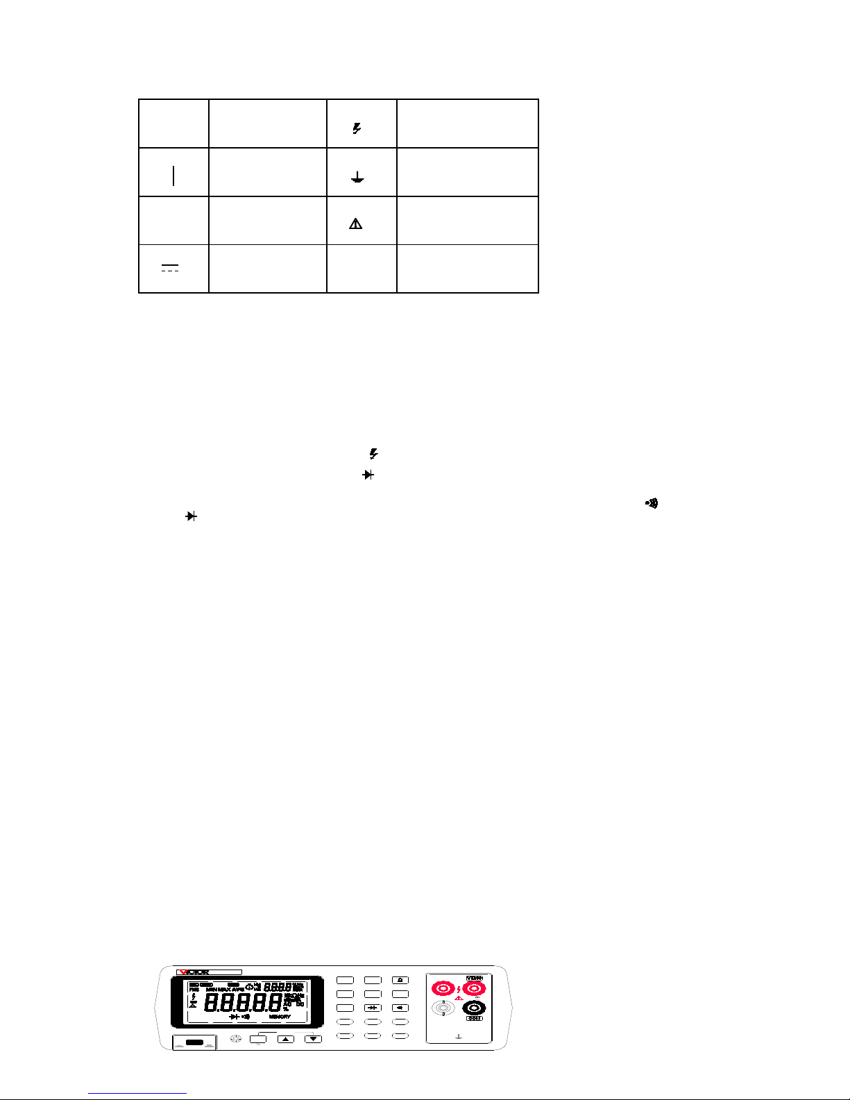
Some common international electrical symbols used in this manual are shown below.
○ OFF(power)
SWITCH POSITION
DANGEROUS
VOLTAGE
ON(power)
SWITCH POSITION
EARTH GROUND
~ AC-ALTERNATING
CURRENT
WARNING INFORMATION
DC-DIRECT
CURRENT
Before using the meter, read the following safety information carefully.
Avoid working alone.
Follow all safety procedures for equipment being tested.
Inspect the test leads for damaged insulation or exposed metal. Check test lead continuity.
Damaged leads should be replaced.
Be sure the meter is in good operating condition.
Select the proper function for your measurement.
To avoid electrical shock, display “ ‘ when working above 30V dc or 30V ac RMS.
Disconnect the live test lead (VΩ ) before disconnecting the common test lead (COM).
Disconnect the power and discharge high-voltage capacitors before testing in Ω, and .
When making a current measurement, turn the circuit power off before connecting the meter in
the circuit.
Check meter fuses before measuring transformer secondary or motor winding current; (See
Section 4, “MAINTENANCE”) An open fuse may allow high voltage build-up, which is potentially
hazardous.
Section 2
Getting Started
INTRODUCTION
Section 2 explains how to prepare the meter for operation, discusses general operating features, and
walks you through the basics of taking some common measurements,
GETTING STARTED
Unpacking and Inspecting the Meter
Carefully remove the meter from its shipping container and inspect it for possible damage or missing
items. If the meter is damaged or something is missing, contact the place of purchase immediately.
Save the container and packing material in case you have to return the meter.
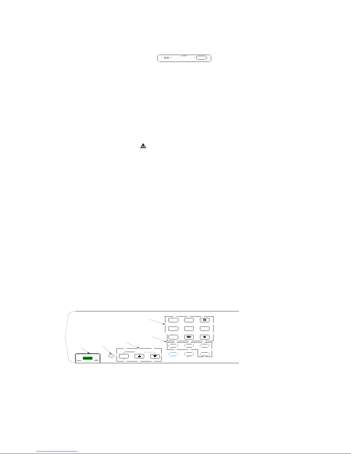
Front Panel and Rear Panel
The front panel (shown in Figure 2-1) has three main elements: the input terminals on the right, the
display and the pushbuttons. The pushbuttons are used to select major functions, ranging
operations, and function modifiers. These elements are described in detail in Section 3.
Figure 2- 1. Front Panel
3
DCV
ACV FREQ
DCA
ACA
AUTO
MN
SHIFT
MX
HOLD
COMP
ON
1
POWER
OFF
0
ALL INPUTS
1KV MAX
FAST FUSE
500mA
250V
mA
10A FUSED
750V
1000V
MAX
RANGE
dBm
REL
RATE
DUAL DISPLAY MULTIMETER
8145B
The rear panel (shown in Figure 2-2) contains the power-line cord connector, communication
interface, the Serial Number Label.
Figure 2-2. Rear Panel
ADJUSTING THE HANDLE
For bench-top use, the handle can be positioned to provide different viewing angles. To adjust its
position, pull the ends out to a hard stop and rotate it to a position. To remove the handle, adjust it to
the vertical stop position and pull the ends all the way out.
POWER
CAUTION
TO AVOID SHOCK HAZARD, CONNECT THE INSTRUMENT POWER CORD TO A POWER
RECEPTACLE WITH EARTH GROUND.
NOTE
Apply the rated voltage and frequency to the meter as marked on the rear panel of the meter.
TURING THE METER ON
To turn the meter on, press the POWER button located on the lower-left of the front panel. If you
turn the meter off, you must wait five seconds before turning the meter back on. If you do not, the
meter will not power-up.
When the meter is turned on, the full screen displays light while the instrument performs an internal
self-test of its digital circuitry. These tests check RAM, ROM, A/D, and the display. The meter has
passed all tests and is ready for normal operation if an error code is not displayed.
After the meter completes the power-up sequence, it assumes the power-up measurement
configuration stored in non-volatile memory. The power-up configuration set at the factory is shown
in Table 3-6. (To change the power-up configuration, refer to “CHANGING THE POWER-UP
CONFIGURATION” in Section 3.)
USING THE PUSHBUTTONS
The pushbuttons on the front panel select meter functions and operations. A summary of basic
pushbutton operations is shown in Figure2-3.
Figure 2-3. Summary of Basic Pushbutton Operations
Pushbuttons can be used in two ways. You can:
Press a single button to select a function or operation.
EXAMPLE: Press ACV to select volts ac function.
Press a combination of buttons, one after the other.
EXAMPLE: Press ACV to select volts ac function, and then press REL to select the decibels
modifier.
4
DCV
ACV FREQ
DCA
ACA
AUTO
MN
SHIFT
MX
HOLD
COMP
ON
1
POWER
OFF
0
RANGE
dBm
REL
RATE
FUNCTION BUTTONS
FUNCTION MODIFIER BUTTONS
RANGE BUTTONS
BACK LIGHT
Press in to Power-up
Press to Step Through
Measurement Rate(Slow,Fast)
Press to Select a Function
Press to Select a Modifier Mode
Press to Select a Range
AC220V 50Hz
THERE ARE NO PARTS TO DISASSEMBLE,
NO MECHANICAL ADJUSTMENTS TO MAKE,
IT IS DISALLOWED TO OPEN THE CASE.
TO AVOID SHOCK HAZARD, CONNECT THE
INSTRUMENT POWER CORD TO A POWER
RECEPTACLE WITH EARTH GROUND.
USB
For more details on the uses of each button, refer to Section 3, “OPERATION THE METER FROM
THE FRONT PANEL.”
SELECTING A MEASUREMENT RANGE
Measurement ranges can be selected automatically by the meter in “autorange” or manually by the user.
In the autorange mode, the meter selects the appropriate range for the measurement reading.
To manually select a range, press AUTO to toggle in (and out) of the manual ranging mode, or press
or . In the manual range mode, press or to up range or down range to the desired range. For
more details on ranging, refer to “RANGING” in Section 3.
TAKING SOME BASIC MEASUREMENTS
WARNING
READ “MULTIMETER SAFETY” BEFORE OPERATING THIS METER.
The following procedures describe the basics of taking common measurements from the front panel.
These procedures are provided for the user who needs to get started quickly, but dose not want to
read the rest of the manual at this time. However, in order to take full advantage of your meter, you
should read the remainder of this manual carefully and completely.
WARNING
TO AVOID ELECTRICAL SHOCK OR DAMAGE TO THE METER, DO NOT APPLY MORE THAN
1000V (PEAK) BETWEEN ANY TERMINAL AND EARTH GROUND. THE METER IS PROTECTED
AGAINST OVERLOADS UP TO THE LIMITS SHOWN IN TABLE 3-1. EXCEEDING THESE LIMITS
POSES A HAZARD TO THE METER AND OPERATOR.
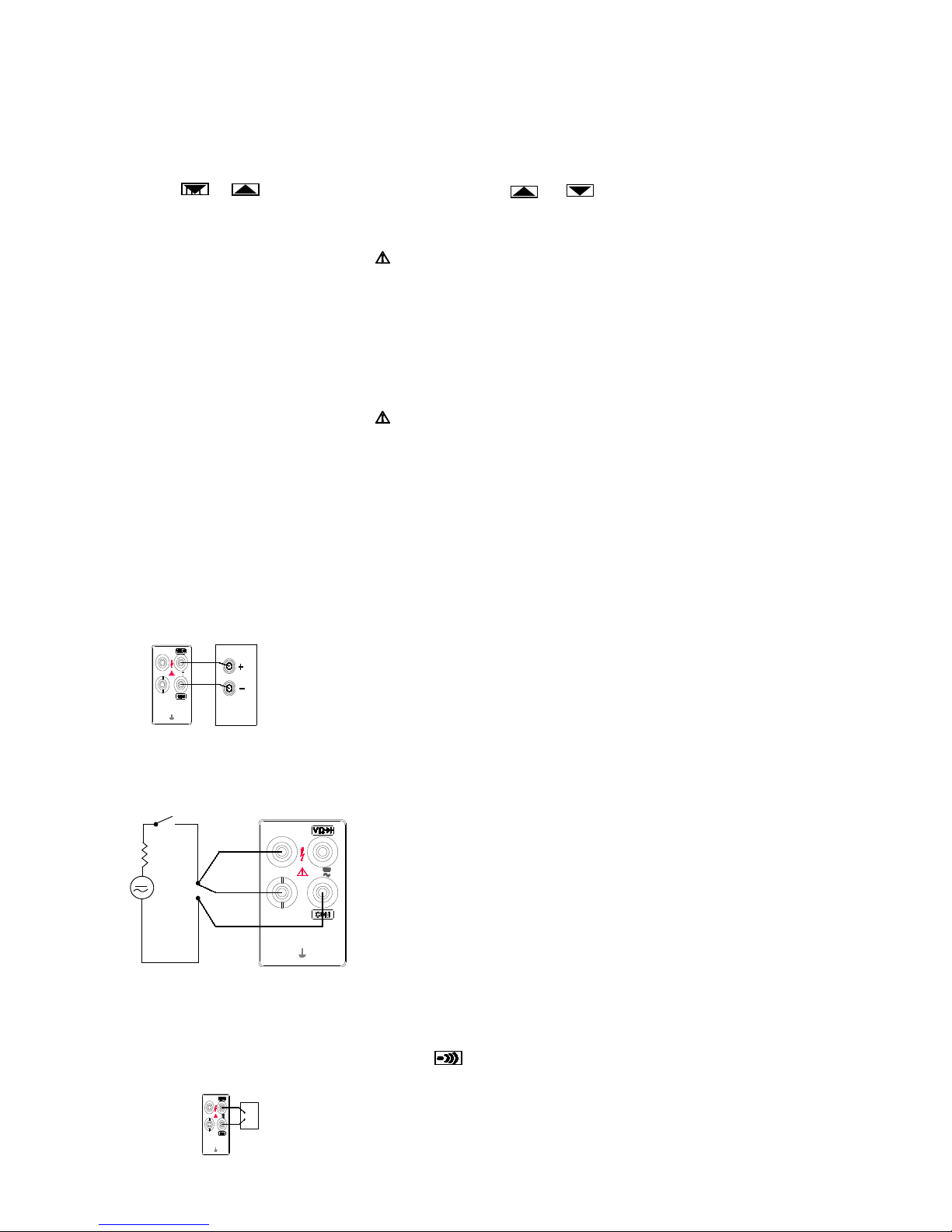
Measuring Voltage, Resistance, or Frequency
To measure voltage, resistance, or frequency, press the desired function button and connect the test
leads as shown in Figure 2-4. The meter will select the appropriate range in the autorange mode.
Measuring Current
To measure current, insert the red test lead in the mA
input terminal for currents up to 330mA or in the 10A input
terminal for higher current, and insert the black test lead in the
COM terminal.
Connect the test leads as shown in Figure 2-5.
NOTE
After measuring high current using the 10A input, thermal
voltages are generated that may create errors when making low-
level dc measurements of volts, current, or ohms. To make the
most accurate measurements, allow up to ten minutes for the
thermals to settle out.
Figure2-5. Measuring Current
Diode/Continuity Testing
The continuity test determines whether a circuit is intact (i.e., has a resistance less than about
150Ω). To perform a continuity test, press , and connect the
test leads as shown in Figure 2-6. The beeper emits a continuous
beep when the input drops below 150Ω (Beep condition can be
changed, refer to “Changing the Power-UP Configuration” later in
Section 3), and the readings for the test circuit are displayed.
The diode test measures the forward voltage of a semiconductor junction
5
MAX
750V
1000V
10A FUSED
250V
ALL INPUTS
1KV MAX
FAST FUSE
500mA
mA
TEST
CIRCUIT
+
-
Figure 2-6. Continuity Testing
MAX
750V
1000V
10A FUSED
250V
ALL INPUTS
1KV MAX
FAST FUSE
500mA
mA
DC Voltage,Pesistance
or AC Voltage
Figure 2-4. Measuring DC Voltag e, Resistance, AC Voltage
MAX
750V
1000V
10A FUSED
250V
ALL INPUTS
1KV MAX
FAST FUSE
500mA
mA
CURRENT
SOURCE
mA
A

at approximately 0.8mA. Readings are displayed in the 3V range at the fast measurement rates. “OL” is
displayed for voltages above 2.0V. Under normal measurement condition, the positive pole of diode is
connected with the black test lead.
To perform a diode or transistor junction test, press to
select the diode function. Then connect the test leads across
the diode as shown in Figure 2-7.
Notice how the test leads are placed. Reversing the polarity will
reverse-bias the diode.
dBm (Decibels) measure
The decibels modifier takes an ac voltage measurement, converts it to dBm (measure of decibels
relative to one milliwatt), and displays the result on the primary display. Connect the test leads as
shown in Figure 2-4.
Press dBm to toggle in and out of the decibels mode. When the decibels mode is selected, “dBm” is
shown on the primary display, AC voltage value is shown on the secondary display.
Decibels can be selected only when ac voltage function is selected. Decibels are always displayed
in a single, fixed range with 0.01 dB resolution. Press the AUTO toggle in and out autorange, you
can also press the . and change range manually.
A voltage measurement is converted to dBm using the following formula:
dBm = 10*lg (1000*value2/reference impedance)
where “value” is the measurement value, and displayed on the secondary display. The reference impedance
can be changed. (Refer to “Changing the Power-UP Configuration” later in Section 3).
Communication Interface
The real time measured value can be transmitted to the computer by the devote USB cable and the
VICTORVIEW_8145B software (refer to “using the communication function”in section 3).
SECTION 3
Operating the Meter from the Front Panel
INTRODUCTION
Section 3 explains how to operate the meter from the front panel.
FRONT PANEL OPERATIONS
The following operations can be performed from the front panel:
Select a measurement function ( DCV, ACV, DCA, ACA, Ω, FREQ, dBm
and )
Select function modifiers that cause the meter to display relative readings (REL), minimum
,maximum or average values (MN MX)
Enter the Touch Hold mode (HOLD) to hold a reading on the display
Set Measurement Rate (RATE), change the rate as “F”(Fast) or “S”(Slow)
Take a measurement and compare (COMP) it to a setting value
Select the manual or autorange mode (AUTO), up range or down range manually to
desired range
Turn on or turn off the back light (when arrive the setting time the back light can automatically off)
Power-on or off the power supply (POWER)
6
MAX
750V
1000V
10A FUSED
250V
ALL INPUTS
1KV MAX
FAST FUSE
500mA
mA
Figure 2-7. Diode Testing
These operations are described in remainder of Section 3.
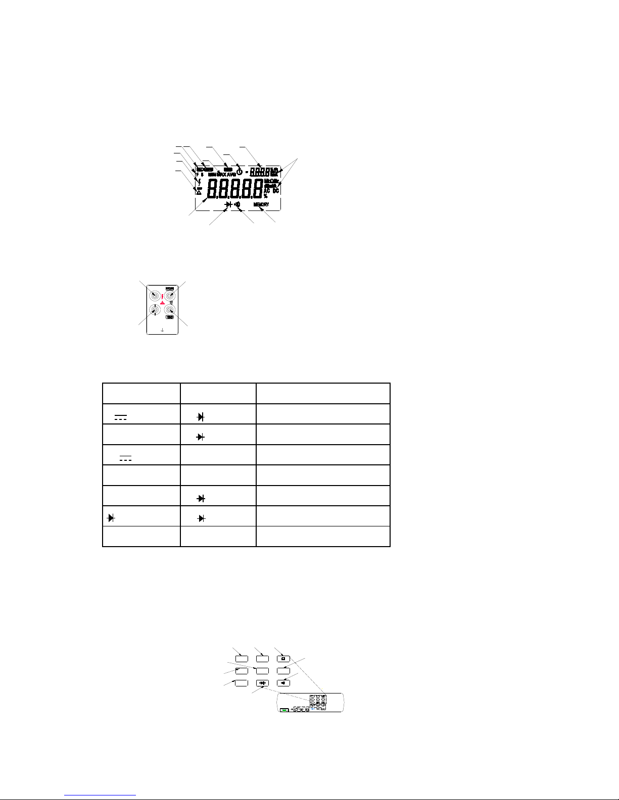
DISPLAY
The meter has a 5-digit, Liquid Crystal Display (Primary Display) and a 4-digit, Liquid Crystal Display
(Secondary Display). The display shows measurement readings, measurement units and
messages. As shown in Figure 3-1.
INPUT TERMINALS
The input terminals, as shown in Figure 3-2, are
located on the right of the front panel
The meter is protected against overloads up to the
limits shown in Table 3-1. Exceeding these limits
poses a hazard to both the meter and operator.
Figure 3-2. Input Terminals
Table 3-1. Input Limits
FUNCTION INPUT TERMINALS MAXIMUM INPUT
V VΩ and COM 1000V dc on all ranges
V ~, FREQ and dBm VΩ and COM 750V ac rms,1000V peak on all ranges
mA and mA ~ mA and COM 500mA dc or ac rms
A ~ and A ~ 10A and COM 10A dc or ac rms
Ω VΩ and COM 250V dc or ac rms on all ranges
VΩ and COM 250V dc or ac rms on all ranges
All Functions Any terminal to earth 1000V dc or ac peak
SELECTING A MEASUREMENT FUNCTION
Press a function button, as shown in Figure 3-3, to select a measurement function. When you select
a function, annunciators turn on to indicate the function selected. Rang and full scale values are
summarized in Table 3-2 for voltage, current, ohms and frequency
Figure 3-3. Function Select Buttons
7
Reading Rate
High Voltage
Relative Modifier
Primary Display
Diode Test
Continuity Test
Save
Function and Unit
Annunciators
Secondary Display
Time
Hold
MIN MAX
Modifier
AutorangeCalibration state
Figure 3-1. Display Annunciators
DCV
ACV FREQ
DCA
ACA
AUTO
MN
SHIFTMXHOLD
COMP
ON
1
POWER
OFF
0
RANGE
dBm
REL
RATE
reading rate
ACA FREQ
DCA
ACV
DCV
Volts DC
Amps DC
Resistance
Volts AC
Amps AC
Diode
Continuity
Frequency
dBm
dBm
8145A
MAX
750V
1000V
10A FUSED
250V
ALL INPUTS
1KV MAX
FAST FUSE
500mA
mA
Volts, Ohms, Diode Test input Terminal
Common Terminal. Retern Terminal
for all Measurements
Amperes Input Terminal. For
Current Measurements up to 10A
continuous
Milliamperes Input Terminal.
For Current Measurements
up to 500mA
 Loading...